draken152
-
Posts
219 -
Joined
-
Last visited
Content Type
Profiles
Forums
Events
Everything posted by draken152
-
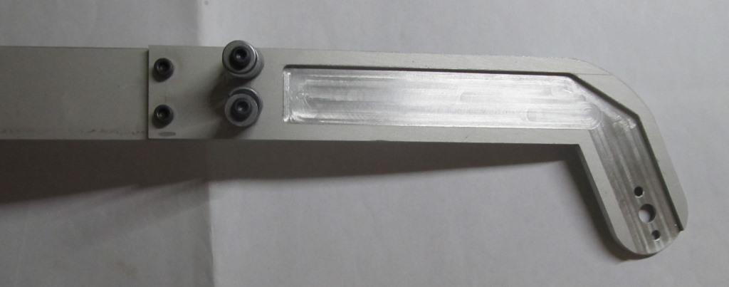
Hi all. Update after long time. I have found almost all necessary dimensions and drawings and now I am playing with aluminium, bosh profiles and laser cuter :music_whistling:.

-
Guys I want to kindly ask for help. Currently I am working on drawing of bottom instrument panel. My work is based on Ta 152 factory drawing of instrument panel (unfortunately without dimensions), photos, numerous drawings from books and some builds of others guys. I am almost done but there are some unknown dimensions for me (for example side edge radius). I know there are some blueprints available on the net, but to be honest I need maybe 3 drawings and I don’t want to pay 60€ for it (also I am not sure if they are included in those blueprints). This build isn’t really cheap and I can use 60€ on something else in my pit..... So please have someone in his possession some useful sources for FW 190 instrument panels - factory blue prints or anything else (and is willing to share it with me)???? :worthy: Thank you all….
-
Thank you for your spelling corrections:thumbup:. My German language is on low level so for me is hard to recognise this kind of issues… I will rework it…
-
I have also durring this project litlle bit improved my skills and rest of the design work I will do in 3D. Also the painting masks for label are prepared, my plan is to airbrush all the labels on both consoles. Currently I am working on design of the grip base. I want to also kindly ask for help. Have someone original blue print for FW190D instrument panels? This is last drawing what I am missing. Please contact me via PM. Thank you.
-
So after longer time here is some project progress. Design work on this is really time consuming. Currently I have finished design of both consoles. Most parts for left console are also produced, for right console I am missing the parts what need to be laser cut (they are already at supplier). This week I have also received last parts for throttle lever. I have also little bit improve the construction of throttle lever (add strengthening to avoid banding of construction and deleted the spring mechanism).
-
They were planned an also tested another two versions of EZ-42 one was EZ-42SP (Selbsttätige Peilung - I haven’t translated whole document so I cannot explain it functionality) and EZ-42 with radar setting of distance using FUG217 radar as part of OBERON system. I have document what you have posted, it is overview of German gunsight development ... For me it is hard to believe all German REVI manuals are showing real shape of recticle only EZ 42 is showing false shape... By the way main competitor of Askania EZ 42, Carl Zeis EZ 44 has only 8 dots as recticle without any helpscale for bombing. For bombing focus was on TSA2... Documents presented by you and me are indicating different things, so as I wrote before - without analyse of real EZ 42 we cannot be sure….
-
Good point Kodoss, I have read manual few times but never think about this sentence. It is for me little bit mystery because also in attached schema from manual is recticle showed like on all another pictures. Generally in all REVI manuals is always recticle shape displayed according to reality, usually also explained... Maybe they planned use different shape from start of project (they were lot of changes) and they forgot to change this sentence, or they planned use different shape of recticle for fighter bombers (Me-262A-2)??? In my opinion is recticle Ok, according to reality. It don't mean your suggestion can’t be right, without analyse of real EZ 42 we cannot be sure….
-
They posted also warning few years ago http://www.deutscheluftwaffe.de/instrumente/katalog/kopien/Kopie%20Revi%20EZ%2042.htm
-
Guys it is replica :)!!!, probably they used same shape of recticle like REVI 16 have. For gyro gunsight this recticle shape don’t have any sense (maybe only when gyro is destroyed). Source for current DCS recticle is EZ 42 manual….
-
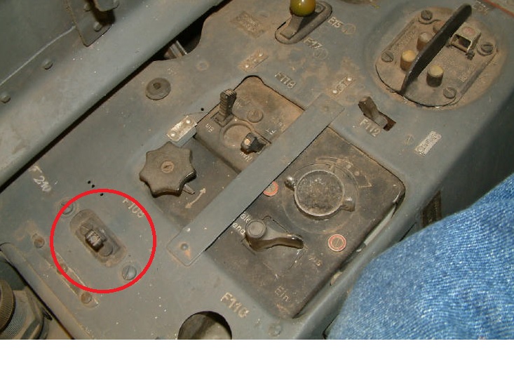
Beta is almost finished, so was this considered by ED. I think Fox one is in this case right. Also in Lehrmittel cockpit layout is visible the position of this switch is in front of fuel pump switch not behind like in current DCS cockpit, also on earlier posted schematic is visible the switch shape… And please also consider the shape of Radio self-destruction button. The design of this button in Anton (see atached picture FW-190A-6 with broken cover of button) is known and there is no logical reason to change it to unsafe solution currently presented in DCS Dora cockpit…
-
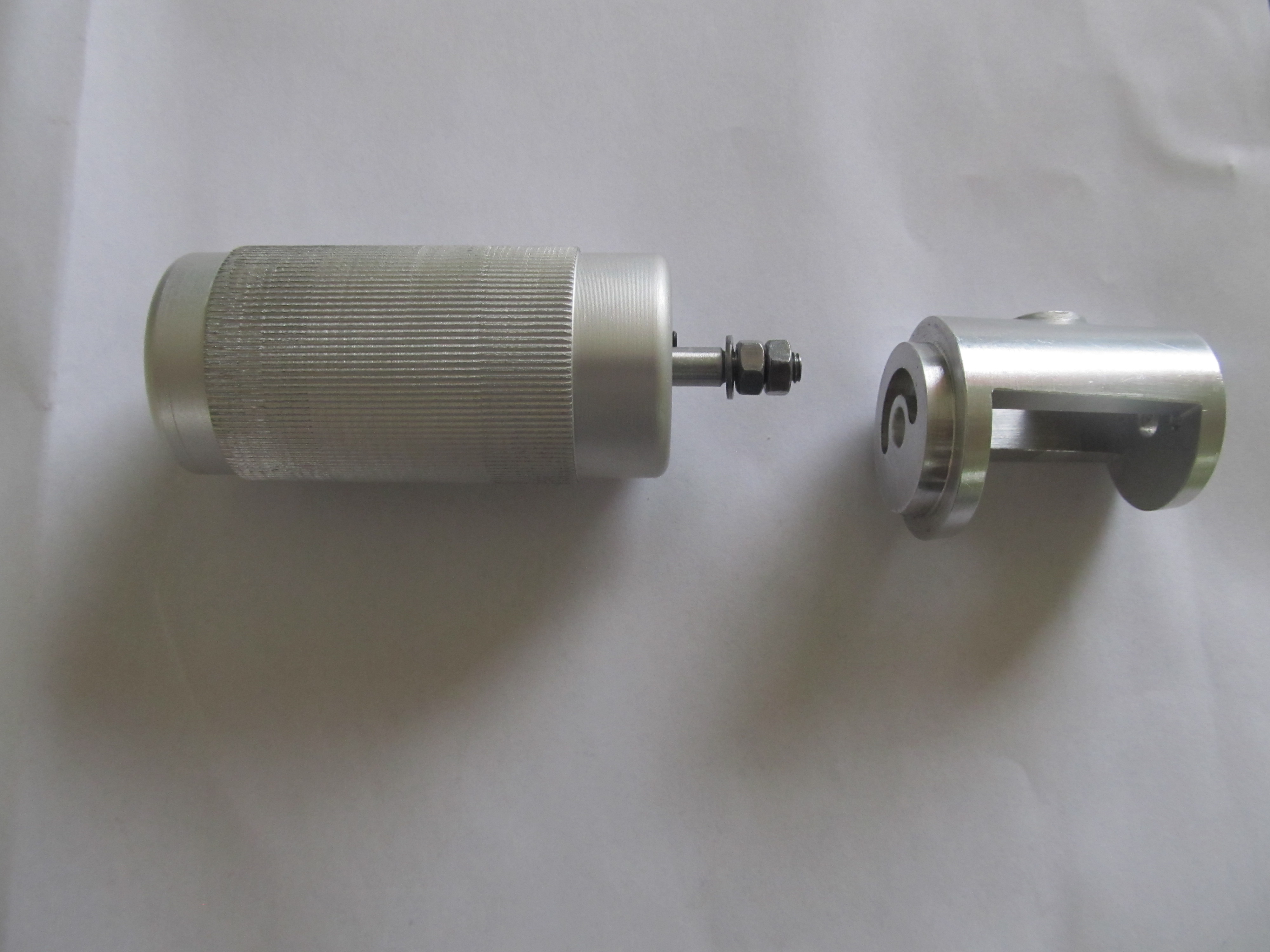
Yes rotating of throttle grip will be functionally ( linear hall sensor). I am just finishing drawings of this part....
-
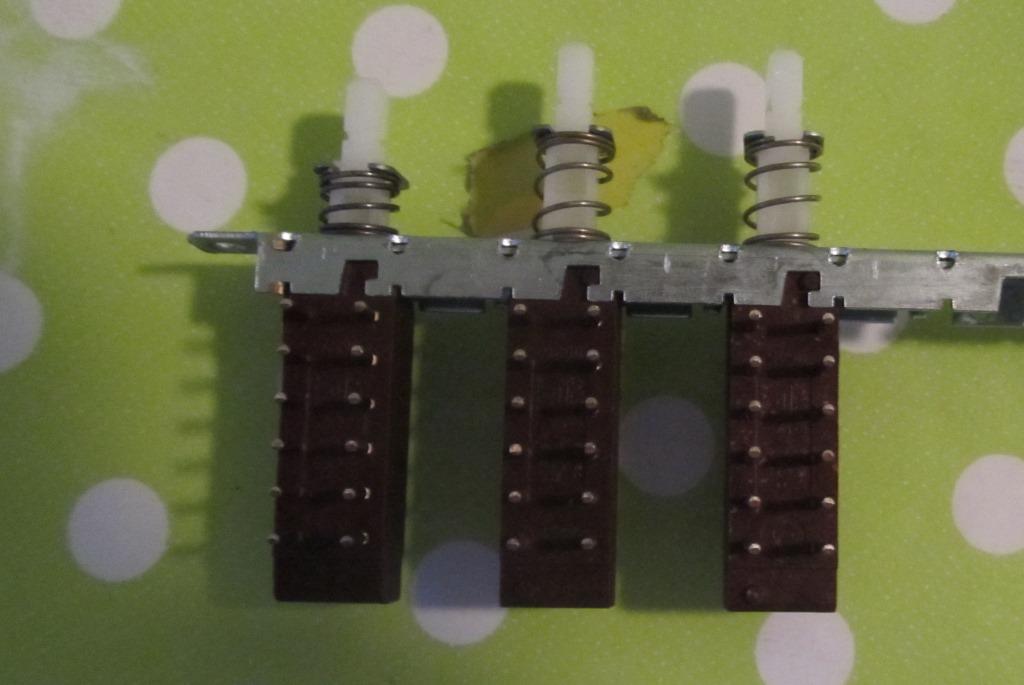
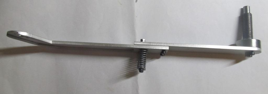
New parts. PCB for gear indicator with four 5V diodes and potentiometer it will be connected to the switch for gear (no controled by DCS, so little bit simplified). On another photo is switch for gear and flaps, it was little bit problem to bough it, this ones are little bit rare in our country. Functionality is same like on real Dora (only one can be pressed) and each is switching two circuits (so MMJOY and diodes). On last pictures is throttle leveller with simplified shape:music_whistling:. I don't know how was on real Dora made this blocking in zero position (maybe banding of leveller???) but I use leveller divided to two part and connected via screws and two springs It is assembled only for test fit, I must use shorter screws and springs.
-
Ok sorry small misunderstood, this was not clear from your previous post...
-
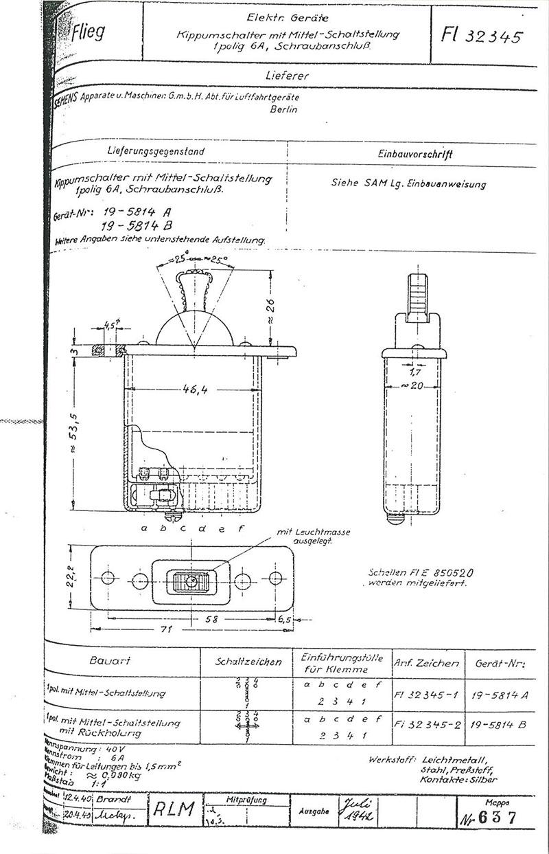
Thanks. We have discussed indicator in this thread http://forums.eagle.ru/showthread.php?t=128829 it looks both options are right. For start I will let indicator unconnected later on I am planning add servo and control it directly from DCS (via card, export.lua, hope it will be possible) . One remark to your solution, in reality trim control was momentary switch (ON)-OFF-(ON) see attachment, so the leveller is always in the middle what you cannot achieve with potentiometer (I was also thinking about similar solution at start). I will use this switch for this purpose https://www.elfa.se/elfa3~eu_en/elfa/init.do?item=35-238-75&toc=0&q=208045.
-
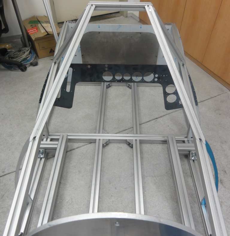
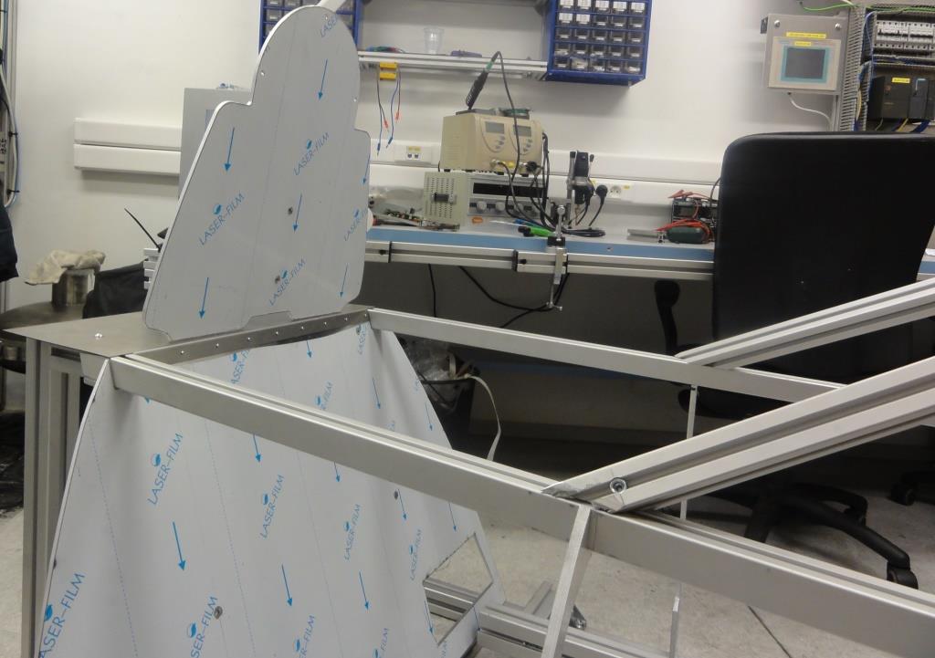
Hi all, It is time to present my Dora project. I am collecting data, pictures and designing components from start of this year (so before DCS DORA release). Layout is based mostly on cockpit pictures of W.Nr. 601088, which is the only original, complete D-9, so they are some minor differences compared to DCS. My first target is to get full functional left and right console of Dora cockpit. Step 2 will be control stick, rudder pedals, pilot seat, and hopefully step 3 both parts of Instruments panel. I let the wood for carpenters and beavers :lol: so my materials are steel, aluminium and polycarbonate. On attached pictures you can see left console polycarbonate body, laser cut cover steel plate, and aluminium CNC machined instruments. Parts are only assembled for test fit. I have just ordered some electronic parts (buttons, switches), MJOY 16 is ready and waiting for upgrade to MMJOY. My big thanks to Kodoss, Fox One and Sokol 1 for their help…
-
Thanks for opinion/advice so it look too me there is currently no suitable KG-13 grip for joystick on the market. I don't know if Baurs grip is still available, but right now is 250€ for me too much, so maybe later:pilotfly:….
-
I am also thinking how to made/buy Kg-13. What about this kg-13. My original plan was to buy KG-13 from Tail Boom and strength it with internal epoxy/glass fiber lamination, do you think it is possible. Have anyone experience with part from simparts.de,???
-
First the fight K-14 vs EZ42 is little bit childish, you cannot compare anything according to one attribute... From Historic point of view: I have only two documents from WWII directly comparing K-14 and EZ42. First are daily reports from Tarnewitz (German research centre for gunsights) and that is also source of these ,,20%-30% less accurate of K-14” ( citation in Erich Hofmans book) in original source there is not mentioned any testing procedure (same FW 190 or anything alse ….) Second is German report from 12.8.1944 describing functionality of captured K-14 and comparing it with in that time existing German gyro gunsights (EZ40, EZ42, EZ44). But this K-14 was not functional so description/comparison is pure technical, part by part, system by system. Conclusion from these documents (not my conclusion): EZ42 was by Germans more precise but the question is if this level of precision was needed. K-14 was from construction point of view (by Germans) more simply to produce and maintain. Installation of fixed sight on K-14 was reported as confirmation of poor function of gyro sight (that was conclusion of German report). But another report from commando Tarnewitz about EZ45 from 22.9.1944 say this: ,, For gyro gunsight EZ45 will be used gyro group of English gyro gunsight.” And EZ 45 was planned as successor of EZ42!!! Is nice to have gunsight with 20%-30% better accuracy than K-14, but when you don't need this level of accuracy and it is 10 time more difficult to produce this gunsight, it don't make any sence(this is my conclusion)… EZ 42 was primary delivered to anti bombers squads so was primary used on Fw190A, for sure not Me262!!! I have some documents about this also…. P.S. I have approximately 300 pages of original documents about German gunsight development, unfortunately not all already translated so some new informations are on the way….
-
Hi good question. Regarding to schematic what I have posted earlier with switch on Revi you are only disconnecting gyros from servo motors of mirror. The 1.5 min is only valid if you switch off general switch (V24), because then you switch off GDU I and GDU II (DC/AC converters what are supplying the both gyroscopes). http://forums.eagle.ru/attachment.php?attachmentid=102422&d=1407509910
-
Normal procedure for switch off EZ42 was to use brightness lever to switch of light circuit . With V24 switch you will also switch off cockpit electrical equipment (cockpit lights....). REVI 16 was using same procedure for switch off. It was needed only to prolong life time of bulb (big temperatures, high G are really bad environment for bulb).
-
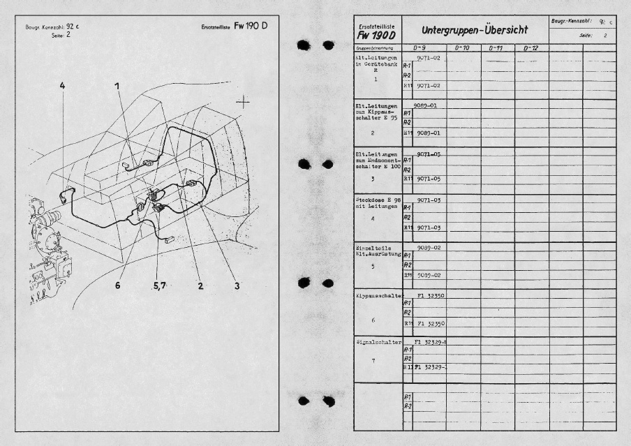
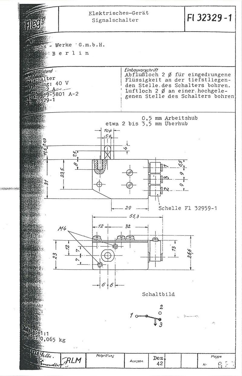
 In reality you can use MW50 only at full throttle. There was hidden switch what allows start only at full throtle... You can see it in scheme from Ersatzteilliste (number 7)....Also this is mentioned in operational instruction for MW 50 in FW 190 Lehrmittel....
-
You can use MW50 tank as aditional fuel tank.
-
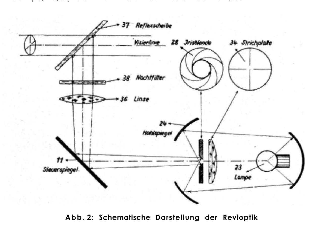
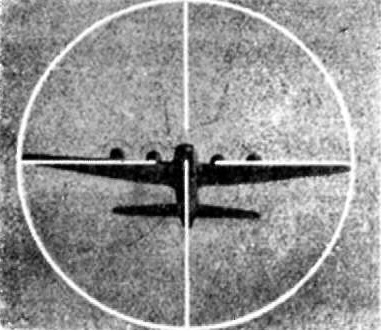
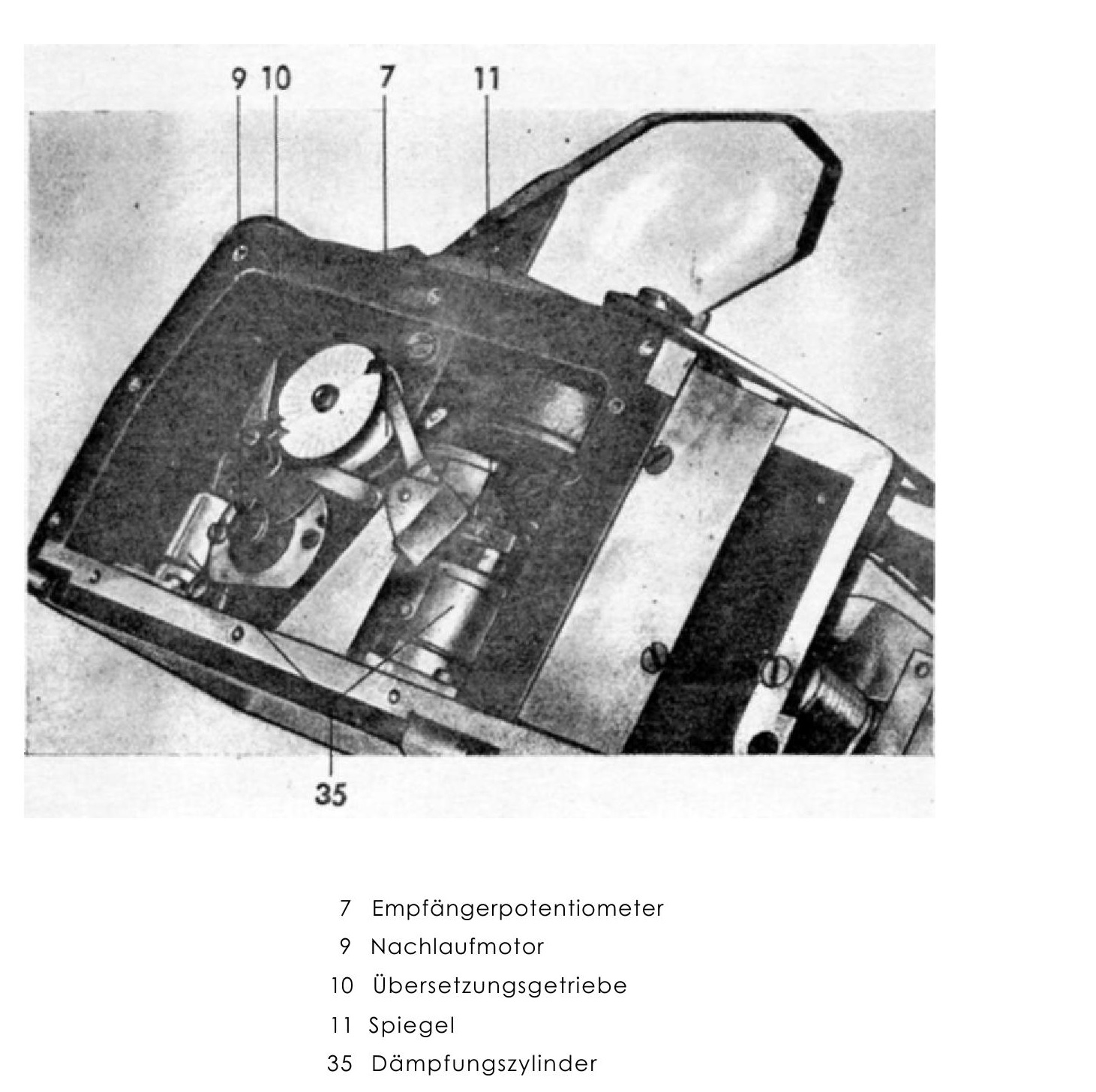
To be honest I don’t think so this is the EZ 42 crosshair (or this is the part of EZ 42), it is missing any evidence of damping system and for me It isn’t looking similar to picture in manual (servo motor in EZ 42 was behind the mirror see attachment). In manual is EZ 42 crosshair clearly visible. Also on your picture is clearly visible 10% ring used on standard REVIs for distance calculation so it is looking they used mask from standard REVI because you don't need this on gyro gunsights (maybe after gyro failure ) for me it is indicating experimental or prototype. You must consider one thing in reality German development of gyro gunsights was running from early 30s and there was lot of experimental gyro gunsight like EZ 2, EZ 6, EZ 31 (and more), some gunsights also passed the gunnery trials like EZ 40, EZ 42 and EZ 44, and some future planned like EZ 45 so there are many opportunities. From my knowledge I am guessing this is from EZ 40 (but Askania EZ 40 not Carl Zeiss), because there was 0.serie production (also trials at field units) and crosshair on EZ 44 was different (when you consider only gyro gunsights produced in more than 10 pcs) ….
-
It is in MP same??? If yes than your enemy had problem:lol: No seriously post some screenshots, I am curious...
-
Fox one I full agree with you. My personal wish is to have 2 Doras, early and late (current) variant. Early without MW50, with REVI 16B, maybe flat cannopy and minor cockpit changes(I know D-9 can be splited more but this could be enough)….Maybe one time:helpsmilie:….