
Triggerhappy69
-
Posts
932 -
Joined
-
Last visited
-
Days Won
1
Content Type
Profiles
Forums
Events
Everything posted by Triggerhappy69
-

Uuuuaaaah..! I have started building now..!
Triggerhappy69 replied to Triggerhappy69's topic in Home Cockpits
Cool..! I need someone to bounce ideas of..! Mine have gone worse and worse lately..! :helpsmilie: -
Uuuuaaaah..! I have started building now..!
Triggerhappy69 replied to Triggerhappy69's topic in Home Cockpits
Thanx guys..! (Blushing).. Tonight I hope to assemble the APU Panel with backlights and all..! If you don't hear anything by sunday, it's all gone to shite..! LoL -
Uuuuaaaah..! I have started building now..!
Triggerhappy69 replied to Triggerhappy69's topic in Home Cockpits
PCB Etching Nope.. Water will not etch away the copper layer.. There are many different approaches to finding the eching solvent that suits you best. The most easy available is probably Ferric Chloride (I think that's the correct name, but please google it before you take my word for it). This is available for "over the counter" purchase at most Pharmcy's.. HOWEVER..! Be advised that Ferric Chloride stains evertyhing it isspilled on, and is a real mess to work with in general.:cry: Also you should be prepared that the chicks working at the pharmacy WILL look at you as if your some kind of freak when you ask for Ferric Chloride.. LMAO..! It least that's what happened to me when I asked for it..? Some swear to Some kind of hydrogen pherokside mix. Also easy to get hold of, but a more unstable fluide when it comes to getting the right strenght.:book: Found on internet about PCB echants:' "I've found a new home-made etchant that I really, really like. And it's very cheap, and widely available. It's made by adding 1 part Muriatic Acid (the common kind that's sold in hardware stores, which is actually 28% Hydrochloric Acid) to 2 parts Hydrogen Peroxide (the common 3% kind that's sold in drugstores and pharmacies). This etchant can etch a 1-oz board in about five minutes, at room temperature, with gentle mechanical agitation. And it's almost transparent. I mix it in a small plastic food-storage container and wear rubber gloves so I can use a balled-up paper towel to gently wipe the surfaces of the board, as it etches, which seems to speed up the etching time, considerably. (Caution: The concentrated acid's fumes would be very bad to breathe, or to have around metallic items. And the acid would be very bad to get onto anything that's not plastic.)" I use powder based eching solution that I bought at my electronics supplier locally.. It works fine, but is kinda pricy in the long run.So I think I'll go for the Muriatic Acid and Hydrogen Peroxide solution as soon as I run out.. copied from: http://www.fullnet.com/~tomg/gooteepc.htm (LOT's of info on this site.. Scroll down and read..!) For a list of the most used PCB etching solvents and how they work (always nice to know WHY things go wrong..LoL) check out: http://www.p-m-services.co.uk/etching.htm Note: Notice what this guy say about the right paper for Laser Transfer of the layout.. I wish I had read that a couple of weeks ago..!:doh: -
Forming pit building group in CA for BS
Triggerhappy69 replied to rocketeer's topic in Home Cockpits
Heads up guys..! I finally got the 4-way switch working...! Check thread in "Tech".. -
Uuuuaaaah..! I have started building now..!
Triggerhappy69 replied to Triggerhappy69's topic in Home Cockpits
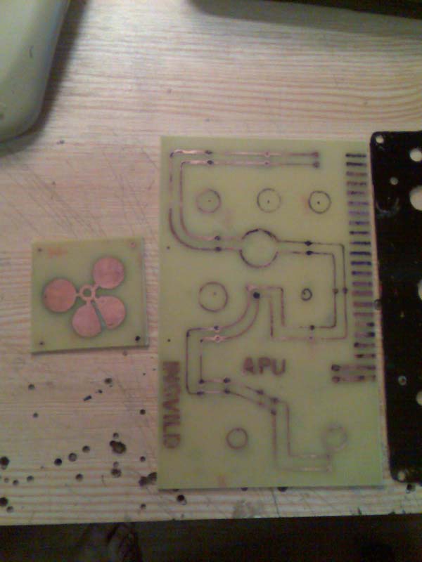
Update: APU Panel PCB layout. I needed to design a new one where all the resistors, relay and stuff was on the PCB. And also I wanted to have the connections running on the PCB itself from each switch to the main cable. Top layout.! And the transferred Layout: For this one I'll use both sides of the blank PCB board. Since I needed to bridge the connections at four points. And the finished Layout transferred to the PCB Board: I'll let you know how it goes.. All the stuff needed for etching is waiting. I just have to get some Cinese first.! The powder is mixed in a 1/5 solution. And is Natriumperoxidsulfate..! No go practice saying that fast 10 ten times..! LMAO..! I'll be back with an update on the etching and putting everything together ASAP.! BTW.. Big discovery on PCB layout transferring..! Print with a Laser Printer on Ink-Jet Photo paper..! Laser Photo paper has a plastic layer that water can't dissolve. And that makes transferring the layout just about inpossible..! :huh: Here the PCB has just been dumped into the Ferro-something-something-something bath. You can see small bubbles of gas forming on the surface at once.. It's actually facinating to see.. 5 minutes into the prosess.. And most of the copper has dissapeared. The teesponn is there to make sure the bottom of the PCB is etched to. And I flipped it over every now and then, and made sure to move the eching liquide arround to speed up the reaction. Not to bad result if you ask me.. Now tomorrow I need to buy a ned Carbide drill that's 0,8mm.. I had four of them, and now I have none.. Hmmmm..? Must be something wrong with my Dremel.. LoL -
Uuuuaaaah..! I have started building now..!
Triggerhappy69 replied to Triggerhappy69's topic in Home Cockpits
Update: APU Panels 4-way Rocker switch WORKS..! I decided to go "russian" in my apprach to this switch, and build prototypes untill I finally got one working. And it turns out this was the right approach after all... The switch is springloaded with a "fueltank klunk" from a model helicopter at the end of it (it has the right round shape, and was predrilled to 3,2mm) At the inside of each of the grooves that the "stick" runs in. I have cut out some pieces of a 0,5mm copper sheet to use as contactpoints for the electric current. And I bent them so they will make contact even after some serious abuse from my part.! Seems to work good so far. Here you see the copper sheet pieces and how I bent them. (sorry for the poor quality pics. I just can't bring myself to fixing my digital camera..) More details.. I'll make drawings of the parts as soon as I have a spare moment.! The only thing missing on the APU Panel now is for me to etch out the new PCB, and solder all the connections to it. I have thrown away the idea about having all the panels come together in a breakout panel for each module. It would be more of work if I nedd to do repairs on one panel while I wanted the rest to work.. It's a learning prosess.. :smartass: -
Happy Birthday..! Hope you have a good one and get all you want..!
-
Uuuuaaaah..! I have started building now..!
Triggerhappy69 replied to Triggerhappy69's topic in Home Cockpits
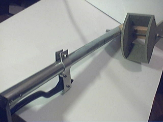
Building the Rotor Governor Handles (Collective Update) Having some time on my hands I got around to building the two handles that control the Rotor speed governor next to the Collective Stick. The first thing I had to make was the alu plate that the handles would stick out from. Here seen as the plate to the right of the collective stick. Also I took the time to shape the holder for the rotorbrake handle.. This was my idea.. To have a 20mm plate inside the rotor governor box, holding a handle on each side that triggers microswitches. The end/center positions will be determened by the cut-out grooves in the alu front (first picture. Not drawn in yet on the plate) Here you see the end and center points drawn on the alu plate. And the Alu plate in it's place on the rotor governor box. The governor handle cut-out placed on the side ov the governor box for test fit. And how I found the end/center points for the handles. Using a hack saw I cut out the handle attaching plate (took some sanding and fine adjusting after, but it came out ok) As you can see one side has a groove sanded into it, while the other side has a alu plate attached to it. This is because the handles are spring loaded as they move from one position to the next. And to make the pivot point for the handles the same I had to sand out a groove on one side. The alu plate on the other side is just to prevent the handles edge digging into the soft wood. And make the whole thing feel more "rigid"..! Here you see how I springloaded the Governor handles. Just some springs I found and a wood screw to hold it. I will have to sand down the threads on the screws where the handle moves up and down, but that's a 5 minute job with a Dremel.. Also you might notice that I had to raise the microswitches about 3mm and add a plate at the end of one of the handles. This is because this handle is lifted up when I move it to it's next position. The Rotor Governor Handle Mechanics assembled and just waiting for me to attach it into the Collective's Governor Box.! The two handles were made from 10X4mm alu rods that I bendt into shape and rounded one end of. The knobs are actually just cut-outs from the front instrument panel that i made a 10X4mm groove into using a Stanley knife. And drilled holes and screwed it all together. At a later point I'll fill the holes in the knobs with expoy, and "paint" the knobs with a thinned out solution of expoy glue (just 5 minutes epoxy glue with a bit of white spirit in it). This should give the knobs a plastic finish and make them more durable for wear and tear. AND give me a good base for painting as well.. And the end result: Well that's all for today guys.. Next is cutting out the plate that the handles move in, and the some epoxy, paint and A LOT of standing back and being proud of myself..:music_whistling: Sunday 30/3-08 Update: I just scrapped the first front for the Rotor Governor Box. And started the looong and boooring way towards making a new one. The old AND the new: I'll try and hurry finishing this now. Everything is just waiting for me to be able to assemble the Collective Mech. New Update here as soon as I have time to finish it.! -
Uuuuaaaah..! I have started building now..!
Triggerhappy69 replied to Triggerhappy69's topic in Home Cockpits
Power supply for pit builders After some snooping around the internet I came over this DIY Powersupply How-To.. It follow the same line as the one I am using, but it also covers a more "safe" and in-depth way to make a stable powersupply from any cheap/free ATX power supply.. Check it out on : http://web2.murraystate.edu/andy.batts/ps/POWERSUPPLY.HTM#POWER_OK -
I have the connection manual for the cougar. It shouldn't be to hard to make that one work. The X-52 on the other hand I know nothing about..
-
Now THIS is possible to build without hacking a working joystick..! URZE: You being a tester and all.. Is this simular to how the FFB feels in BS?
-
Well since I've allready made the cyclic stick handle for the KA-50, and have a FFB that I never use. And the mechanics will be integrated into the front pedestal anyway. That Settles it for me..! Might as well go all the way and make it feel as real as possible..!
-
That's what I like about you dude..! Always one step ahead of me..! Keep me posted..!:thumbup:
-
So what your saying is that, for example, when you puch the cyclic forwards to increase the relative air speed (and you have to add some collective to maintain level filght). and then press the trim button, the preasure on the stick is removed.? And this becomes the new mechanical zero-point for the cyclic stick? That will be a challenge to incorperate into my pit..? I do have an old FFB stick that I can Hack..? If this is part of the simulator...?
-
I have been studying the movie of a pilot flying a demonstration flight in a KA-50. You can download the movie from: http://www.virtual-jabog32.de/index.php?section=downloads&subcat=29&file=807&lang=en It seems he's fingers are pressing working overtime on the buttons and/or trigger while flying? [ATTACH]15610[/ATTACH] Notice he's right index or ring finger pressing a button almost every 3 seconds..! What the heck is he doing?:cry:
-
That is soo cool..! I have followed your thread on 3rd Wings forum, and I'm glad to find that I can finally try this editor out..! Good work..
-
Uuuuaaaah..! I have started building now..!
Triggerhappy69 replied to Triggerhappy69's topic in Home Cockpits
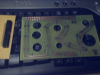
APU Panel update and pcb making Damn I am getting tired of working on this ONE panel.! But it's kinda crutial because it will set the standard of how all the other panles are made, and it holds a 4-way switch (Aaaaaargh.. I hate that thing) I started of by printing the PCB layout so all the backlight led's were connected. This PCB will also hold the slider plate for the 4-Way switch. These will be transfered to the blank copper PCB boards ing a hot iron you can transferre the laserprint on to the copper boards (Remember to print on InkJet Photo paper, and not Laser Photo paper) Soak the whole thing in HOT water, and carefully remove the paper that turnes into "goo". Be carefull to not remove the Laser print transfer though. It should stick well to the copper proven that you have cleaned and scrubbed the PCB before ironing the print onto it. Also remove ALL greasy fingermarks, as this will ruin the transfer.! (Took me a while to read that part.. Stupid me.) You should be left with something resembling this. ... But I wasn't..! So I had to do some touch up work with a eching pen..! My final result came out quite good in the end if you ask me. And now the parts are just waiting for me to sand the Backlight LED's matte (to better dispurse the light.. This makes a HUGE difference.!). And re assembly..! More on that later..! Last night I painted the major cockpit modules..! It's starting to come together now..! Damn this is getting fun..! -
Uuuuaaaah..! I have started building now..!
Triggerhappy69 replied to Triggerhappy69's topic in Home Cockpits
I have no idea why I haven't thought of that yet..? Sigh.. Simple sollutions.. gotta love'em..! Thanx mate.:thumbup: -
You'll find it on the website http://www.leftside-limited.com/index.html Only Urze can say answer with 100% certainty, but I seem to remember something about this from when Urze launched this cool mod..!?
-
Uuuuaaaah..! I have started building now..!
Triggerhappy69 replied to Triggerhappy69's topic in Home Cockpits
Picture update PCB making for the APU Panel ... Bummer..! No more space for pics..! Is it possible to increase the space I have for pictures? Teaser:
-
:thumbup:.. That has to be one of the funniest...! (actually laughing my ass off)
-
Simpit Ka-50 from Razorback
Triggerhappy69 replied to Razorback's topic in PC Hardware and Related Software
Really excellent work man..! i Hope I will live up to this building standard.! How about releasing the dim's for the outer shell though? It would be helpfull..? -
Uuuuaaaah..! I have started building now..!
Triggerhappy69 replied to Triggerhappy69's topic in Home Cockpits
Thank You guys..! I am making a short How-To make easy PCB and breakout boards for the DIY guy..! More pics and an updtae on the Cyclic Stick trigger mechanism by Tuesday and Wednesday next week..! -
Uuuuaaaah..! I have started building now..!
Triggerhappy69 replied to Triggerhappy69's topic in Home Cockpits
Pitbuilding Update Collective Stick and PCB making Finally got some time to work on the Left Rear wall and Collective stick today. I had to figure out how long the stick handle was going to be, and for that I had to first finish the Front Panel and attach it to the Front Pedestal. Then I could place the Left Lower Panel and Ejectionseat and the Left Rear Wall with collective Stick. Phuuh.!:music_whistling: Naturally I got so carried away while doing this I forgot to take pictures of (half) the pit assembled, but I promise to do so within the next few days... After finding the correct lengt for the collective handle I fixed the Collective switch box and just got started making the attachment for the collective break handle before bedtime arrived.. Collective Stick with the (un-finished) collective break handle. As you probaly can see from the pictures I have still got to file the ends round on the handle attaching plates. The Collective Stick "business end".! Here you see the axel that it pivots arround in the Left Rear Wall, and the box that will hold the Rotor Governor Control Handles) My first self made PCB..! This is just a rough test board that will connect all the LED's for backlighting the APU Panel. And also all the wires from the switches and rotaries. But now that I know how easy it is to etch PCB's I'll design a new one that also holds the 4-way switch and it's mechanics. OooH..! I have forgotten to tell you all..! I found a way to make the 4-way switch that actually is simple, feels right and WORKS..! Was going to keep it a secret untill I cuold show you pics of a working example, but now the secret is out..! DAMN ME..!:cry: I unsoldered some 39 pin IDE connectors from a broken computer mainboard I had. And after sweating and swearing over it for an hour or so, I finally found that the ONLY way to unsolder all 39 pins at once is with a industrial heat-gun (basicly a blow dryer on steroids). You will most likely need quite a few of these if your building a pit. Just to avoid having to un-screw hundreds of individual connections to do simple repairs or upgrades in the future.! So my advice is: Get one of those heat-guns, or buy them from an electronics suplier..! This board gathers all the wires from all switches, LED's, rotaries and so to a common place in the Left lower Panel. And I'll use standard IDE ribbon cable to route everything to the IOCards. Also it holds the resistors for the different LED's and relays to toggle the Backlight on and off.. Well that's all for now folks.. :pilotfly:
-
Forming pit building group in CA for BS
Triggerhappy69 replied to rocketeer's topic in Home Cockpits
Same here..! Having followed the MFD discussion within the Viperpit comunity. And theyr struggle to get the MFD's up in working order (without the HUGE Fps drop). I put my faith in the fact that we'll get it working someday..! ED seems to have theyr finger in the pitbuilding pulse (BIG rep to you for that Mr. Eagle Dynamics), and the LUA exporting from DCS seems to be have ample room for growth. .... also the front panel looks really wierd with that big screaming hole of nothingness on the right side.. So I am whipping out my soldering iron and in goes the encoders..!:thumbup:


.jpg.f1f6deaee4924c1ebb0330d969b39589.jpg)