Triggerhappy69
-
Posts
932 -
Joined
-
Last visited
-
Days Won
1
Content Type
Profiles
Forums
Events
Everything posted by Triggerhappy69
-
This site will be a "stop by regulary" site for me..! Congrats Urze..! Ps. Still not able to get my Skype working.. Should we try Messenger instead?
-

Uuuuaaaah..! I have started building now..!
Triggerhappy69 replied to Triggerhappy69's topic in Home Cockpits
I have gotten hold of a pair of Suspa 100N Gas Springs now. They have linear dampening, so I hope that if I do as you say the springs will cancel each other out without problems..? Working on incorperating the pedals into the Front Pedestal assembly today, but I have set aside a couple of hours to flying LOFC online.. I miss my 'Frog'..! -
Uuuuaaaah..! I have started building now..!
Triggerhappy69 replied to Triggerhappy69's topic in Home Cockpits
I agree with you both.. Rep to Nordic guys..! -
Cool.. Lot's fellow Norwegians here..! I'm also from Norway BTW..
-
Uuuuaaaah..! I have started building now..!
Triggerhappy69 replied to Triggerhappy69's topic in Home Cockpits
Sorry guys.. I got you mixed up for some reason.. Serves me right for posting late at night I guess.. :doh: -
Uuuuaaaah..! I have started building now..!
Triggerhappy69 replied to Triggerhappy69's topic in Home Cockpits
Don't do any modding to your pedals mate.! I made the center consol so I could make some simple "helicopter" pedals integrated into the center stand. Choppers need to be flown with the pedals out of center all the time. So I made pedals that can be used without having to move your heel at all (lesson learned from flying EECH with fixed wing pedals... and suffering from cramps in both legs!) The pedals are made up from stuff you probably have in your garage, and the most complacated parts are skateboard bearings that are the same all over the planet.. Have you ordered your IOCards from Opencockits now? Then your wait will be short.! Those guys really deliver..! As I mentioned I have started making a spreadsheet to get some kind of overview of all the "stuff".. I'll send the spreadsheet to your e-mail this weekend so you can look at it and tell me I suck.. :book: In times like these we must keep our heads clear and our pants on my friend..! Or at least the first thing.!:megalol: -
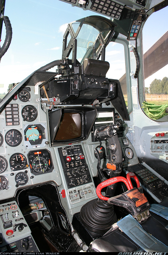
Would you do me a favour Groove..? BOW TWICE..! Once from me as well..! Wasserfall? I am in awe over your detailing.! I think I actually felt a twiching in my crouch area when I looked at your hydraulic tubing in the model.. Just beautifull..! :thumbup:
-
Uuuuaaaah..! I have started building now..!
Triggerhappy69 replied to Triggerhappy69's topic in Home Cockpits
Blush.... You Guys..! Thanx guys..! Ps. Nordic? Could you send me some info on how you made your pedals? I was sure I had it somewhere, but I must have lost it? -
Uuuuaaaah..! I have started building now..!
Triggerhappy69 replied to Triggerhappy69's topic in Home Cockpits
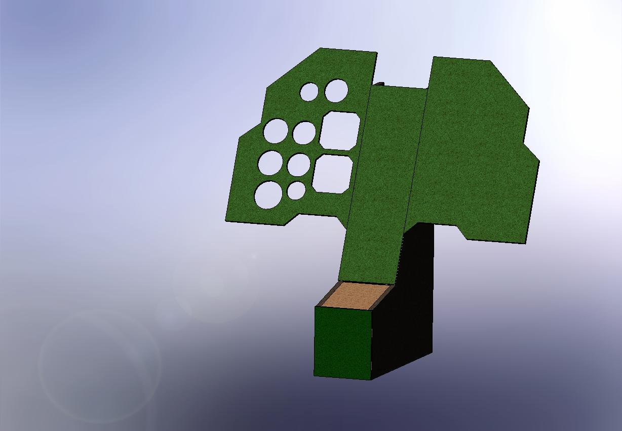
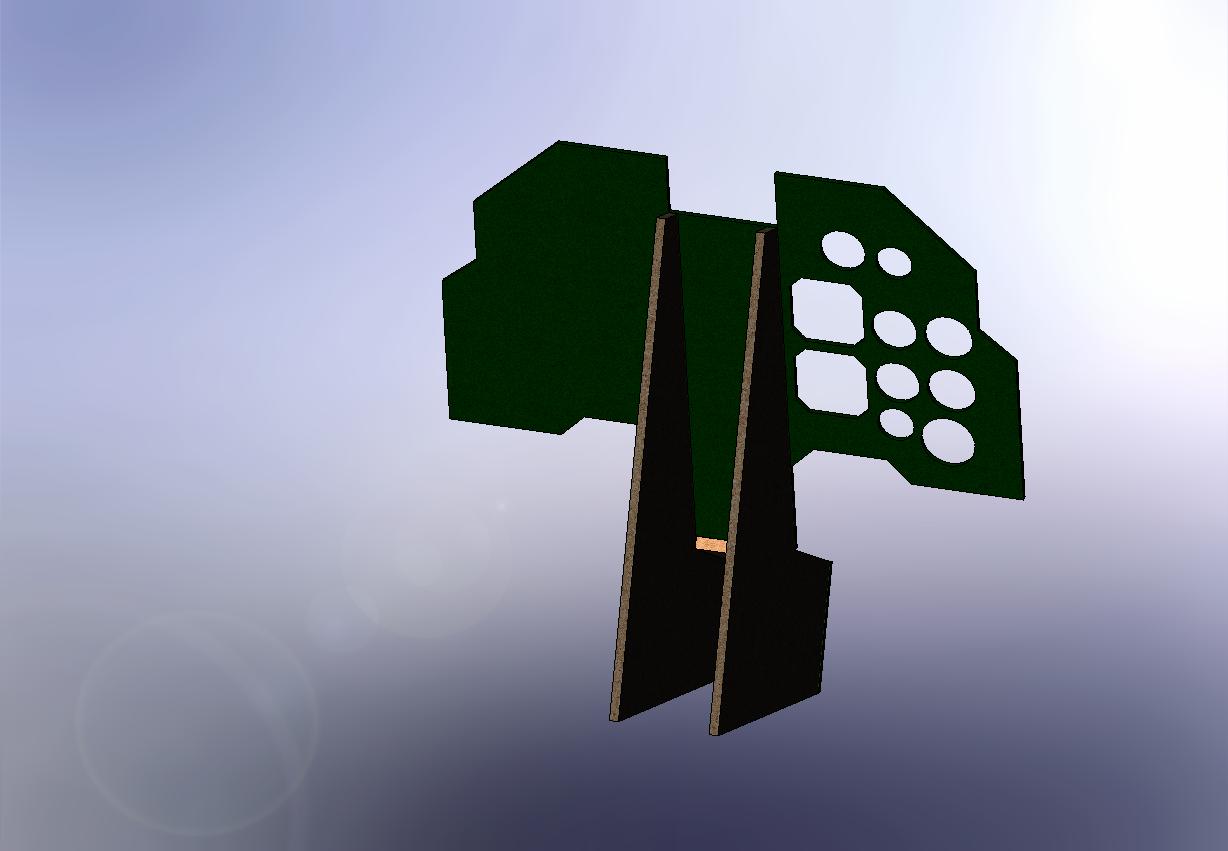
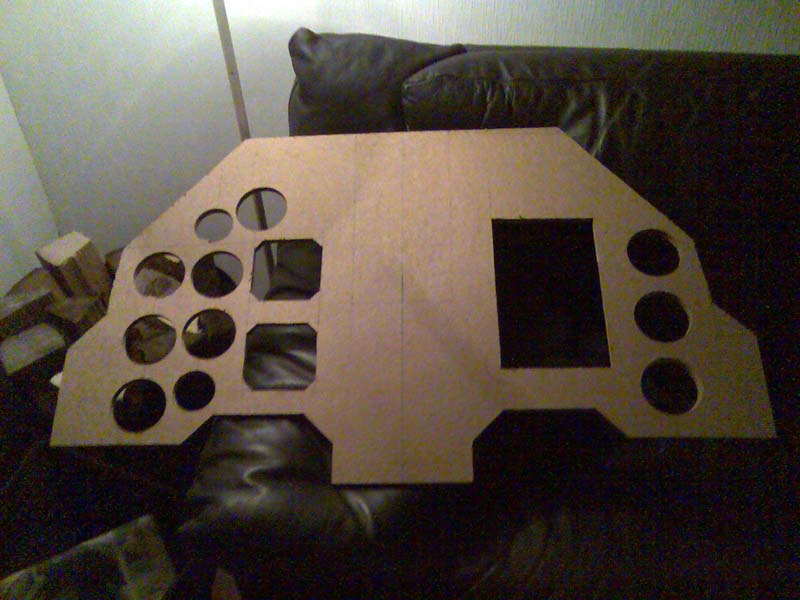
Ka-50 Main Front Panel Building a cockpit has so far been a series of new and unexpected challenges.. Take for instance the fact that the pit not only has to look somewhat like it's original, but also has to have proportions that actually will work when sitting down in it..!? And this later issue is so far the hardest obstacle to pass.. I have measured and drawn and cut (MDF plates, plexiglass and the odd accational finger...:cry:) Also it has become clear to me that without some kind of plan of progression I'll get frustrated and bored long before it's finished.! Why am I telling you this I hear you ask? (feel free to repeat to yourself at will..) Well..!? Status right now is that the seat in it's rough and undetailed state is finished. This was my first build, since the rest of the cockpit is related to the pilots referance anyway. The front center pedestal (where the cyclic is attached) is done. The left front side-panel with both APU&Turbine start panel has been made, rejected, made again and rejected once more. But now both panels have been redrawn. And drawings have been sendt to my CnC contact for finishing. Until he's finished I will connect the latest version i made (and the only one you have seen). I have spent hours trying to make an spreadsheet where I can keep some control of In/Outputs , wires , powersources , switches , relays , buttons , rotating switches , encoders , servos , steppermotors , encoders , LED's and Aaaaargh..! :helpsmilie: Unfortunately all of these things are time consuming and not really worthy of a Pitbuild update on the forum. At least not untill it's finished. HOWEVER..! I have reached a milestone tonight. Finally I have settled on the size of the Main Front Panel and its Gauges. Originally it should be a two-piece, horisontaly split, panel Like this... Since I'm not sure if I will ever be able (or patient enough) to build the HSI and VOR, and probablt will start by projecting these two instruments on an LCD screen. I have made the panel flat so I use a small LCD behind these two Gauges. The other gauges will be buildt with servos. Just because I know I'll have such fun tinkering with all the cogwheels and motors. And here it is.. It might seem insignificant, but it set's the referance point for everything in the pit exept the pilot... The plate is a 12mm laminate of unknown type. And it will have a 1mm plastic plate bonded to it's front to give the right texture apperance (and hide wires and fixing points for lighting and instruments behind it). Next on my list is fixing all the pits modules together, and make pictures for you guys.. But that will have to wait a couple of days.. :music_whistling:
-
Uuuuaaaah..! I have started building now..!
Triggerhappy69 replied to Triggerhappy69's topic in Home Cockpits
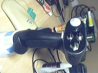
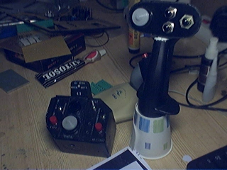
KA-50 Collective and Cyclic stick building - Update Yahoo..! I got the coolie hats from Guillemot techincal Support (Thanx a lot Guys..!) So I can finally continue on the stick and collective building..! The Cyclic has just one Coolie hat. Now that I have it in it's place, I whish I had made the switch box approx 10% smaller. But what the heck! It looks good and works fine..:( Both of them.. The Collective has two coolie hats. Unfortunately one of them broke in transport, but I made an emergency repair. And I just don't have the patiience to return it to Guillemot techincal Support. I'd like to take this oppurtunity to thank the guys at Guillemot. They have really been fast and expedite. It turned out the weeks of wayting was due to slow postal service between Canada and Norway.. So again THANK YOU Guillemot techincal Support ..!:thumbup:
-
Uuuuaaaah..! I have started building now..!
Triggerhappy69 replied to Triggerhappy69's topic in Home Cockpits
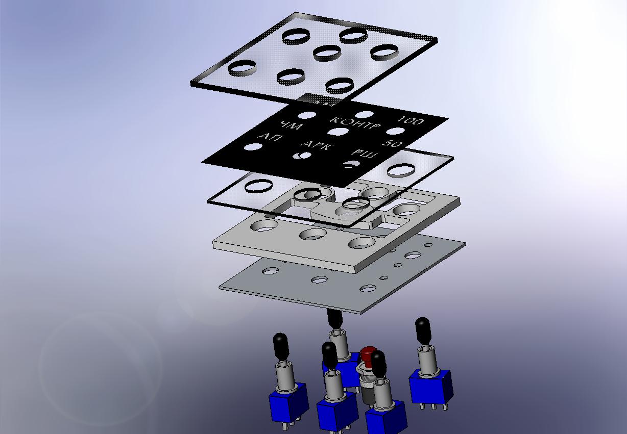
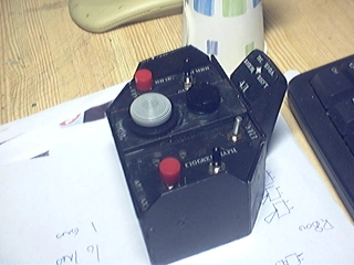
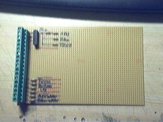
R-800 Panel building Half of the R-800 Panel is finished. Still need to sand the edges, and paint it.! The backlights will come from 3mm LED's. And I will redo the print paper so it looks like the APU panel (.. May need to aquire some Photoshop help..) All the parts.. BREAKOUT BOARD: Just started making the Leftside breakout board. This one will hold the connections to the LED's, and the Reed Relay that controlles them (the samll black thingie).. I have tested it already, and it seems to work just fine with the IOCard's 5V oputput switching the Reed Relay and admitting a 12V source to run the LED's. The lower connections in the picture are the outputs for all the warning lights. They will run on the 5V output from the IOCard, but I put them on the same breakoutboard to try and have some kind of system on my resistors. A seperate breakout board will hold all the switch connections. And the two board will connect to the Masterboard via a cable of some sort.. More on that when I make my mind up.. LATER MATES..!:thumbup:
-
Uuuuaaaah..! I have started building now..!
Triggerhappy69 replied to Triggerhappy69's topic in Home Cockpits
making announciator switches Sorry mate.. My Bad.. LoL.. There are a lot of different good ideas out there on making announciator switches.. All depends on what kind of tools you have accsess to I guess..! I found a guy who has a brilliant idea that's cheap to..! He makes the switches out of table leg plugs He just turnes them up-side down and fit a pushbutton switch behind.. And at the open end he sticks a square piece of plexiglass and a printed sheet of choise..! And BOY does it look good..! He has A BUNCH of other good tutorials for just about anything to..! Check out he's website.. I wish I knew he's name, but I couldn't find it on he's site? But Whoever he is.. He has my respect for KISS solutions..! Being kinda lazy, I have opted for this way (look about halfways down the page): http://home.hccnet.nl/jwopdenakker/IOcards.html -
Uuuuaaaah..! I have started building now..!
Triggerhappy69 replied to Triggerhappy69's topic in Home Cockpits
I just finished building it tonight.. Heres the general layout. Drawings coming later (and Pics) Now It's dinnertime..! Yahooo!
-
Uuuuaaaah..! I have started building now..!
Triggerhappy69 replied to Triggerhappy69's topic in Home Cockpits
Front Pedestal Drawings done.. 02 This is what it will look like if you build it according to drawings. I have finished mine now, and are in the prosess of swearing and cursing my way through cutting the instrument gauge holes.. :cry:! And here's the Zipped E-drawings file..: [ATTACH]15000[/ATTACH]
-
Uuuuaaaah..! I have started building now..!
Triggerhappy69 replied to Triggerhappy69's topic in Home Cockpits
Front Pedestal Drawings done Oh.. C'Mon..! You ment to pry.. And you had good reason to as well.! :music_whistling: I promised you these drawings weeks abgoe, but I haven't been able to finish them before now. The main reason for the delay were these two pictures. My first front panel was WAY to high...! [ATTACH]14996[/ATTACH] And I also saw form this picture how small the cockpit really is.. Not a lot of forwards room here.. [ATTACH]14997[/ATTACH] But here are the drawings mate.. Sorry for the delay.:cry: Front Center Panel KA-50.PDF Front Left Panel Outlines KA-50.PDF Front Pedestal Side.PDF -
Su25 Simpit by Gromich
Triggerhappy69 replied to Gromich's topic in PC Hardware and Related Software
You might not have to..? http://forums.eagle.ru/showthread.php?p=445330#post445330 -
Forming pit building group in CA for BS
Triggerhappy69 replied to rocketeer's topic in Home Cockpits
Hey guys.. I just had a sneak in here to remind you all that my offer to Gromlich is extended to you all..! I have a K-36D seat originally buildt for a Su-25 Pit (an ended project), and anyone who want's it are free to take it..! Ps. I do live in Norway BTW.. So you'll have to figure out how to get it home.. -
Su25 Simpit by Gromich
Triggerhappy69 replied to Gromich's topic in PC Hardware and Related Software
I HAVE A EJECTION SAT FOR YOU...! My K-36D ejection seat is just sitting under the stears collecting dust since I started the KA-50 pit.. If you want it, you're free to have it ? -
Su25 Simpit by Gromich
Triggerhappy69 replied to Gromich's topic in PC Hardware and Related Software
... crying out of joy .... It's .... just ... beautifull .... ! :thumbup: I salute you for being one of the few to take the plunge and build a frogfoot pit... ! I sure as h.. miss mine... -
.. damn .. That's a sweet skin.. Makes me want to .... Oh bugger..! I forgot it's not released yet..!? Rep inbound anayway...
-
Uuuuaaaah..! I have started building now..!
Triggerhappy69 replied to Triggerhappy69's topic in Home Cockpits
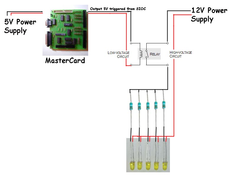
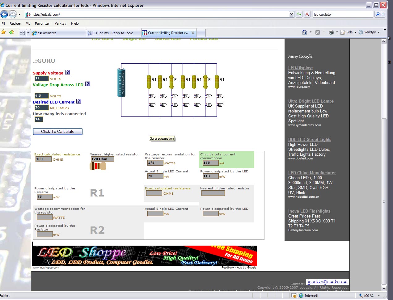
Connecting LED's Well... I use the output from my Opencockpits master board to controll the LED's on and of. There are two ways of executing this that I have considered. The first is to Have the Master board give a 5V output (it runs on 5V) to each and every LED. This would mean that the outputs on the main board would soon be filled up. And that would be a total waste of outputs... 'Cause you'll need quite a lot of them in the Pit.! Let's look at the instrument Panel backlights first: As I previoulsy have said, I have 14 LED's that backlight the APU Panel alone. And if we start counting how many I'll need for the whole pit, it sums up to be a quite high number. Now.. I assume that switching the backlighting on and of in the pit will be done by one command for all of them. So I only need ONE output from the MasterCard to do it. However I can't run all those LED's on one 5V output from the Mastercard without having to worry about overstraing it.. So I have come up with this simple sollution. As you see I connect the Mastercard to the 5V power supply (beacause it runs on 5V). And as I flip the switch for the baclighting it will give a constant 5V output from one of the output cannels on the card. This 5V current will trigger a simple relay that again opens for the larger 12V power supply's current to run through it and out to the ressistors.. The resistors are quite nessesarry since Different LED's run on different voltages. If the voltage is to high it just burnes up! And if it's to low it doesn't emitt any light at all..! So by adding resistors you can fine tune the current to the be correct for the LED's to shine brightly without breaking. And by using a simple LED Calculator at http://ledcalc.com/ you can calculate the correct resistance for the current you need with the number of LED's you want to light up.. It's really quite simple one's you try it out..! For my APU Panel I punched in the LED Calculator the output voltage of 12V. And then a voltage drop of 4,5V for each LED (you can find the voltage drop for the color LED you're using by pressing the question mark on the page. Or by checking the manufacturers specs). My white LED's run best on a 30 milliAmp current. And I want to run 14 of them in series.. And 'voila..! Out comes the resistance needed and a simple chart showing how to connect them..
-
Uuuuaaaah..! I have started building now..!
Triggerhappy69 replied to Triggerhappy69's topic in Home Cockpits
Hey Cat..! Do you mean the forward panel? This one? I'll make a drawing with all the measures on and post it here.. Is that ok ?
-
Uuuuaaaah..! I have started building now..!
Triggerhappy69 replied to Triggerhappy69's topic in Home Cockpits
That was good news mate..! :thumbup: I'll keep updating the drawings for the general layout drawings for the gauges in our folder on MSN. So keep looking every now and then.. I have just started soldering the board that holds all the resistors for the LED's on the forward left panel (where the APU panel sits).. And I have decided that I HATE LED's..! I am using an old computer power-supply to power all the different lights. They are easy to find for free, and give a steady 5V and 12V output. Allthough I think I'll probably need 4 or 5 of them to power all the lights and IOCards in the pit... I just finished giving the APU Panel a coat of paint now.. So tomorrow I'll start making the R-800 UHF Radio panel.. It shouldn't be as complicated as the APU panel. But it will require a bit more programming after since it will mainly consist of the toggle switches, Pushbutton switch and LED. AND four rotary encoders that control six 7-segment displays to project the frequencies.. I did initially plan on making an all mechanical panel, but then it dawned on me that this would require for me to manually reset the frequencies before restarting the simulator? By controlling the 7-segment displays with SIOC I hope to bypass this.. Because I just know I'll forget everytime and hate myself for it..!:cry: I'll post pics and updates as it moves along.. Tonight I assembled all the parts of the pit in my "game room", and discovered that my Collective stick is approx 10cm to long.. BUMMER..! It's to late now, but I'll whip out the 'ol grinder tomorrow and cut it to lenght. I was watching a movie on youtube from the Ka-50 cockpit and noticed that it's really quite small. So now I have to make some slight modifications to the side panels (mainly the right side, that i thank god haven't finished playing with yet :music_whistling:). Well it's a labour of love this pitbuilding.. But I guess it kepps me from roaming the streets at night looking for old ladies to rob..?:cry: Last minute comment: I have made another attempt on building the 4-way switch. And failed miserably AGAIN..! This little thing has really put up a struggle to not function. But I have one more idea I need to test before I just give up and use something I can buy.. My next attempt will use a combination of magnets for the outer positions and a spring from a ball point pen to center it.. Whish me luck guys.. I know I need it..! Trigger out! (of my mind) -
Uuuuaaaah..! I have started building now..!
Triggerhappy69 replied to Triggerhappy69's topic in Home Cockpits
YOU GUYS..! (..blush..) (..no really..! BLUSH!..) :blush: -
Uuuuaaaah..! I have started building now..!
Triggerhappy69 replied to Triggerhappy69's topic in Home Cockpits
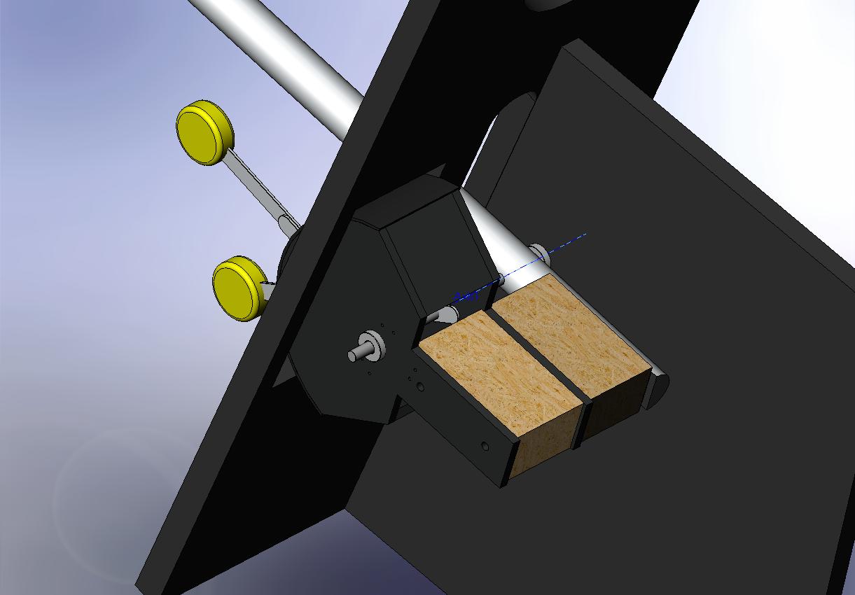
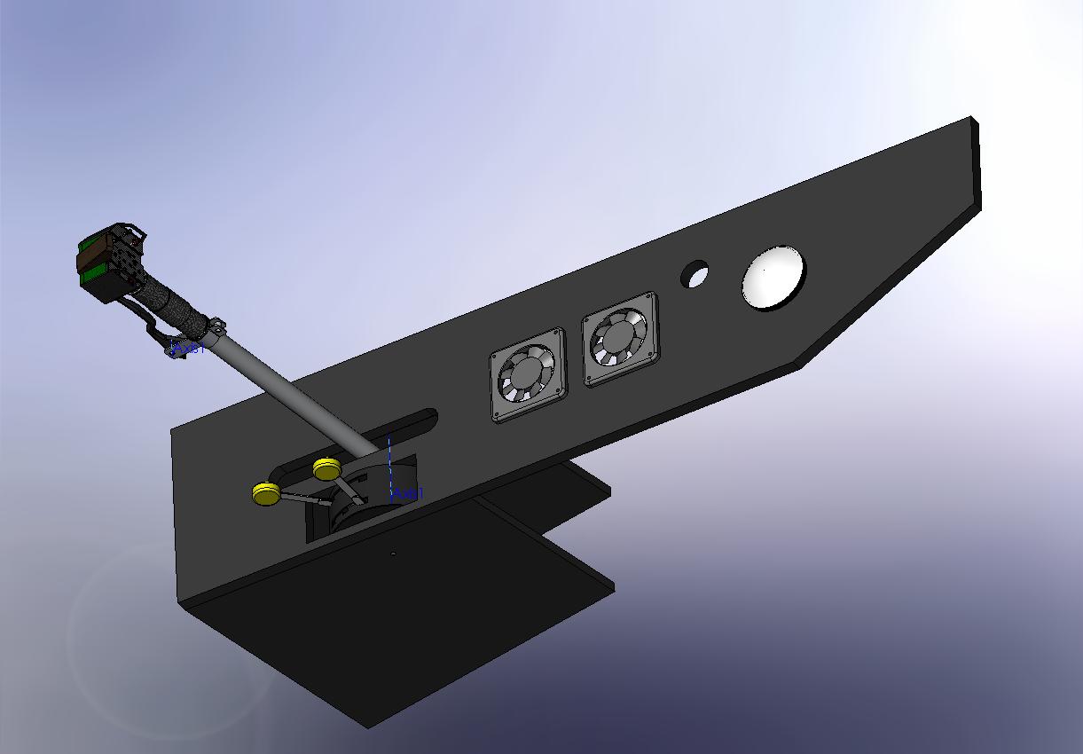
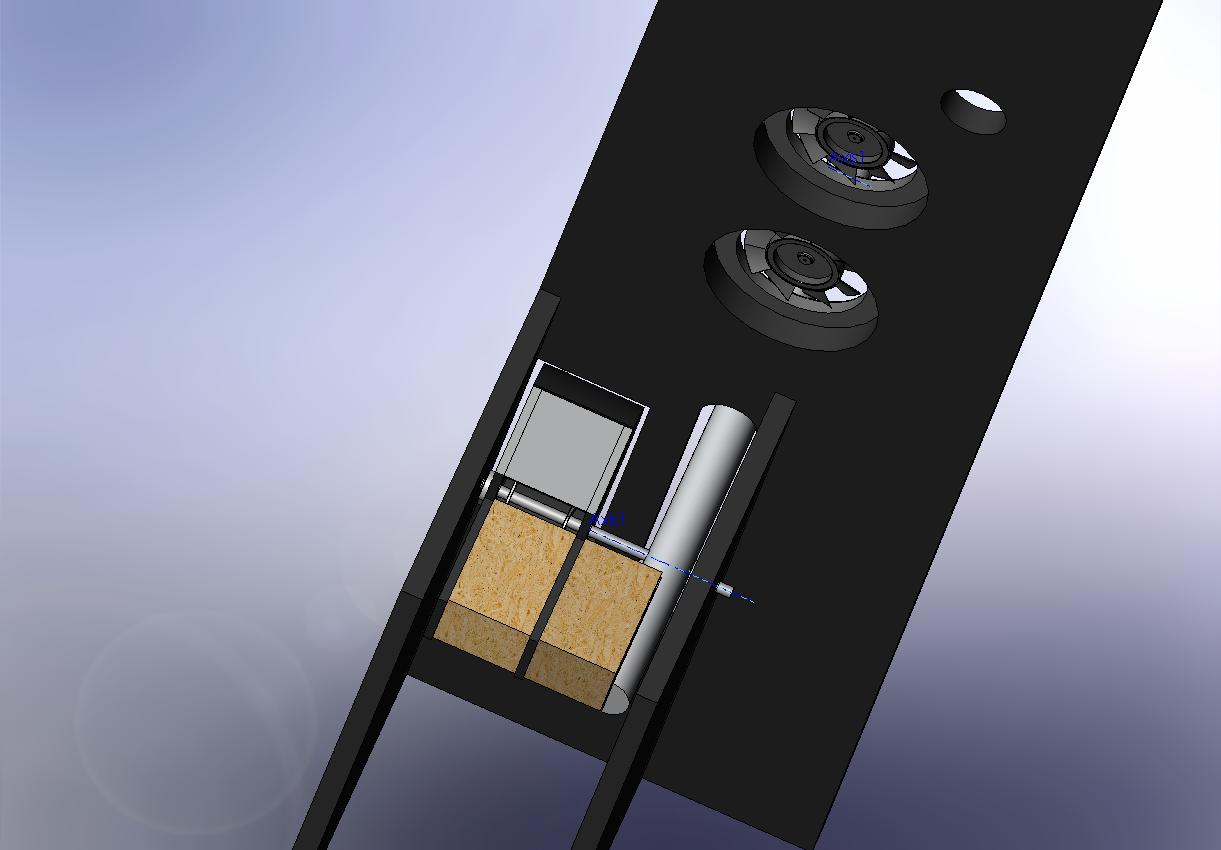
Pitbuilding update 05 february 2008 - Collective assembly Here's a little explanation to what this will do..! This is more or less what it will look like when finished (or so I hope) And this is right now: The holes are for 120mm cooling fans and some lights. As you see only the Collective handle and grip are attached as of right now. The Collective box is finished and sitting right next to me awaiting the Coolie-hats arrival from Thrustmaster.. Should be here any day now.! And the Collective Brake mechanism is under constrution, it to will be added at a later point. The collective pivot point is really quite straight forwards. It moves both the collective and the Governor as one. And pivots arround a 8mm threaded rod on some cheap skateboard bearings thats inserted onto the side walls. View of the collective mech from above: And the real thing: I am working on the detailed drawings for the governor box with it's rolling protection screen and some other stuff.. It's a lot of guessing so far since I we're short on detailed pics. But it's a work in progress.. TODAY'S POP QUIZ: This is the collective sticks max angle. It designed to let my arm rest in a comfortable position at the collective mid-range. And the height is Set according to the height of the K-27 Ejec tion seat I built earlier.. (see page 2 or 3 or 4 or something of this thread I think) Now for the quiz..! What is the "correct" working angle for the collective? I'll try making an e-drawing of the assembly and post it as a zip file here, It might be to big though? So if you want it just send me an PM..!! (Edit: It came out as a 4,6MB File.. So if you want it you'll have to PM me..! Or I could do as I originally planned and get my finger out of my arse and finish the drawings with dimentions..! But I dread starting on that 'cause it's such a bore..! LMAO.. I guess I'm just naturally lazy) More later..!:joystick:


.jpg.fc1b233b456b6e91374931a6ebc73e14.jpg)

.jpg.bdbfc02a67ec4d354c9055bc44f97b0a.jpg)