Tekkx
-
Posts
319 -
Joined
-
Last visited
Content Type
Profiles
Forums
Events
Everything posted by Tekkx
-
Hi Snipes. As DCS-BIOS sends in general just updated data if there has changed sth. (eg. the value - resp. turning angle of your pot) I suppose the value of your pot is fluctuating. This is called jitter. There are inside the library already inbuilt filters to prevent this kind of "flooding" as described by you. If they (these filters) won't do their job (I mean) you'll won't become happy with your pot anyway. If you look a the "flooded" data you'll see the range your pot is virtually moving. I would replace the pot as a very first step in troubleshooting. From all gained experiences I can tell, about a half (or more) of all strange behavior is blamed to bad (or even damaged) hardware.
-
Hi Mole. Same message is to be seen if you unplug a device while running. So my assumption is, your USB-Devices lose their link. Please recount ALL(! means: also Keys, mice, VR a.s.o.) your USB-Devices. I bet your USB ports are overloaded. And: Don't trust specifications of the manufacturers of your USB-HUBs or PC-mainboard. They are all liars in the matter of connectivity ;) We do not know, how you connect your USB-Devices. USB is always critical. Add (not cascade them) some more active (means: with additional 5V-supply) HUBs and do not overload those ones. I use maximum 3 Ports of a 7-port-HUB to prevent such problems. Maybe it's time for you to switch over to a RS-485-System (Master - Slave)?
-
This sends either "1" or "0" if something has changed - if opened or closed the Cover. Somehow you could "catch" this and convertt it to your preferred value. Look in your dcs-bios control-reference for further details. I have right now no acces to a running system. And my "DCS-BIOS speaking" isn't that fluent. ;)
-
What if you multiplicate your value by -1? I'm away of a PC so I can't check out by myself. Good idea with magnet and Hall sensor. I would have used a reed contact. Gesendet von meinem K4000_PRO mit Tapatalk
-
Hallo Hans. It's always fun, watching you at work :) Edit: I wrote a concern here. But than I deleted that just a few minutes later because it was arbitrary. (I thought those 2k are too small.) :) So just left my admiration to Hans' work ;)
-
Great work. Your gauges look like stripped from the real plane. I really enjoy admiring your progress. [emoji106] Gesendet von meinem K4000_PRO mit Tapatalk
-
Wow. Really nice view. But: is your amazing cup holder still working during this maneuver? I watch this project almost from start: I want to thank you for sharing this adventure with us. Great. Gesendet von meinem K4000_PRO mit Tapatalk
-
Jealous on that. I plan to drill it myself.... OMG!!! Will have to make some what like a Jig. What about this? https://photos.google.com/photo/AF1QipN9hWYUtQbHCV6DjUaov6VJ9j6R7vbpf-lOOwWS I use it and it's almost perfect. (quiet slow a bit) It is just to stack on an UNO. Visible area is 73 by 48,5 mm (green rectangle, I drawed on the protective film), vertical distance (center to center) between LSBs is about 10mm. As I don't know the measures of the Real Thing... Ask, if you need some other dimensions. :) Purchased it at China. https://www.aliexpress.com/item/2017-New-Arrival-3-5-inch-TFT-Color-Screen-Module-320X480-Ultra-HD-for-UNO-and/32806100432.html Have a medium sized Box filled with that (as I planned to build a batch of CDUs to commit it to the community - but I found much less time as intended :( ) See some pictures of the whole project here: https://photos.app.goo.gl/e5s8gbk8vlNBDIHR2 (The swagging is just for demonstration ;)) If you dont want to go the long way (4 to 6 weeks by Aliexpress): I could give you one of mine plus a ready programmed UNO. Delivery should be just a few days. Edit: You do an amazing piece of work there. Hats off!!!
-
No and Yes. :) It's understood, you'll need two points to close a "circuit". It's all relative. But it's going too far, if I start to explain the nature of Logic-Levels. It's not my natural environment and ... not my language. So you have to trust me. :) Spoken in "Arduino": You will have to connect your wire to something like a Ground-Potential ("Ground" means here: a few Volts lower than the Output) to pull down an Output. If you have a Matrix there happens something similar: You connect two wires of different Voltage-Level (Potential). If you connect two wires of your Matrix, Arduino will interprete this (if there is the adequate code running) as pushing a certain button. Short answer: Don't care for Ground! Keypad-Library will do that for you. edit: Thank you, Andrew. You already sent your post as I was still typing. :)
-
Hallo, Mr_Burns. Glad to see, you not surrendered yet. :) As the wires at your Photo are a little bit cluttered, I just assume everything is OK. One Leg of a Button/Switch is connected to Row, the other Leg is connected to Column? I can't see, what the two blue wires (some longer than the others) are for. Diodes are just for pressing more than one Button at one time. I suggest, to let them out. Just for the beginners phase! The Switch2Pos-Function (or -Methode?) is not appropriate here. Also it can just read ONE Pin (Pin" means a real physical pin of the Arduino. In a Matrix this works a little bit different.): DcsBios::Switch2Pos ufc6("UFC_6", PIN); This is an example copied out of the http://dcs-bios.a10c.de/docs/v0.5.0/control-reference.html. As you'll see, there is just one PIN variable used. sendDcsBiosMessage("UFC_6", "1"); This is an example of code, I used in the matrix. There are some differences to the first example: First: It is not linked to a PIN, but it sends a command to DCS each time it is called. In the example it says: "Push Button 6 of the UFC!". Second: It says just "push" as there is noted "1" (for "Push"). Release the Button will be another command. ("0" is here for "Release") Look at former posts of this Thread: You have to define a Matrix also inside your code. Otherwise Arduino do not know what to do. You have to write some code to tell trhe Arduino under wich circumstances (condition) it has to send "Push the Button" (or: "Release the Button"). This is all done inside the code example somewhere at the start of this Thread. Look there. And: Hang on!!!! Someday you'll get it! What kind of Plane to do want to control with your device? You UFC-examples are of the A-10C.
-
ICBs: I put them yesterday into the "PackStation" at DHL. Should arrive Wednesday. :pilotfly:
-
Oh. I failed myself: D2 to D13 are 12 I/Os. Your answer is close, but false. "42" (not "41") is the answer to “life, the universe and everything”. With 11 I/Os you can make 5x6=30 Inputs With 12 I/Os you can make 6x6=36 Inputs Connect a Pot like this: Left leg (or left lead out): to GND Right leg: to 5V Center leg: to analog Pin of Arduino
-
Now you get it: Look at your Table (BTW: well done): You have just one mistake: Replace the names of the Heads of your Cols and Rows. You cant use a Pin twice!!! Use (examplification!) D2 to D5 as Cols and all other D..s as Rows. Examination Question 1: How many Buttons (Maximum) can you connect if you have 11 Inputs/Outputs (D2 to D13)? Q2: How is a Pot to connect to an Arduino?
-
As I wrote, you need for Rows and Cols DIFFERENT Pins. Means: each Row has to connect to precise ONE Pin, each Col has to connect to precise ONE Pin. So the answer to your question is NO. Your Pots will work.
-
Hi Warhog. Pleased to see you. :) Don't gras me up to the others: I have a similar Microscope here. :music_whistling: It is just a question of patience (or better: the lack of it). It's an awful boring job to stare at each trace of a PCB with 65 buttons. It has been the first time, I encountered such a problem. All other PCBs I made are not at this size. So a close visual inspection isn't that problem. :) I cleaned an etched PCB (few years ago, one of my first trials) with ultra fine steel wool: Never again!!!!!
-
Hallo Mr_Burns. As I have no experiences with those materials I can't give any helpful information. What kind of Matrix do you plan to make? I forgot to answer (While I did some think-about your last question other matters came in front of that. Sorry.) your last question about "making a Matrix of Potentiometers...". The short answer is: No! The long answer is: No! Interpreting the Output of a Matrix by DCS-BIOS is just possible, if the "keypad function" sends explicit values. Visualize your Matrix as a Map (Countryside or City - no matter): If you have to describe a special point on this map you have to tell two explicit coordinates. Call them X and Y. If you say: "X is about ... and Y is about ... " you'll never find your target. Matrixes made of Pots are sometimes used to mix different Audio-Signals to different Outputs. But even this is complicated as there are Op-Amps (Operation-Amplifiers) at each Pot to prevent unwanted Feedback, Crosstalking and other unwanted interfering behavior. Type "Matrix Potentiometer" into the input mask of any search engine and you'll see. Connecting more than 10 Pots to your Cockpit shouldn't generate an insoluble problem: Thanks to the Implementation of RS-485 to the DCS-BIOS-System in conjunction with the extreme low prices of Arduino (and Family) you can add an adequate amount of Arduinos to your system. If you want to build a Matrix with generic Switches or Buttons, you'd rather create it of wires which are soldered from Switch to Switch. It is just a question of planning (best with a piece of paper) and recording (also with pencil and paper). I do not recommend etching of PCBs to beginners. More than ever double-sided ones (means PCBs, not Beginners). It is tricky, expensive, dirty, destructive (if you don't care enough) and toxic (to the user and to the environment). Counterproposal: Obtain a few pieces of different(!) colored thin wire (25 to 22 AWG, stranded or not doesn't matter - I started a few years ago with a stripped LAN-Patch-Cable), a good tool for dismantling and try it this way. Example: (typed just "matrix switches wired" into Google Photos. First hit is linked here) https://goo.gl/images/Retwes Open a new Thread for this project. Maybe it is interesting to others too. Good Luck!
-
Dear Mr_Burns: Don't fear! We do not need any Capacitors to connect Switches to an Arduino :) First: It is not possible to turn 12 Inputs into 60. Maybe, we have to clarify, what "Matrix" means: Take a piece of paper and draw some (not too much!!!) horizontal, parallel (means: they mustn't touch each other) straight lines on it. Get it? Now draw in similar way some vertical lines which cross these horizontal lines. Get it? Now count your horizontal lines: This is value "A". Write it down! Now count your vertical lines: This is value "B". Write it also! Now count all Intersections between your vertical and horizontal lines: This is value "C". Now multiply "A" by "B". The value of the result should be the same as the value of "C". Get it? Imagine, each drawed line is a piece of wire and at each Intersection we could set a Button to connect 2 lines. Each vertical Line is linked to an Output, each horizontal Line is linked to an Input of our Arduino. So "C" is equal to the maximum amount of Buttons we can have in our Matrix. What do this mean? With 12 Inputs you can make a Matrix with a Maximum of 36 Intersections (6 multiplied by 6 as we just have 6+6=12 Pins), where the amount of Intersections is the same as the number of different Output-Values. (If 6x6 is the max Quantity you can easily test by tryout 6x6=36, 5x7=35, 4x8=32 aso.) Maybe the feasible Maximum (in our example) is less than the calculated Maximum, cause we need 6 (half of 12) Pins that we can configure as Output. Analog Pins of the Arduino aren't available for setting them as Output. This is reserved just to the digital Pins D2 to D13. I have attached a Schematic of a simple 3_by_3_Matrix. The diodes are just necessary, if you want to press more than one button at the same time. This will happen if you use not just momentary buttons (as for a keypad) but switches that stay where you switched them. You can follow the lines in the Schematic: If you want to connect a special Col with a special Row, there will be just ONE appropriate Switch (or Button) which is to close. Here is an example (code): char keys[3][3] = { // Define the Keymap / upper and lower cases matter {'1','2','3'}, {'4','5','6'}, {'7','8','9'} }; // Connect Matrix Rows and Columns to these Arduino pins. byte rowPins[ROWS] = { Input1, Input2, Input3 }; // any free Pin is useable, except A6 and A7 // just present at NANO byte colPins[COLS] = { Output1, Output2, Output3 }; // just digital Pins - If you want to get "5" as the result, you have to connect Col2 and Row2 - If you want to get "6" as the result, you have to connect Col3 and Row2 ... Important Note: No Ground (GND) is involved in such a Matrix!!! Buttons and Switches connect just Outputs to Inputs (which represents Cols and Rows)! Drawing a Matrix on a paper is very easy. Problems will turn up if you start to wire these (worst case: different) switches. To keep track, you (and me and most others also) HAVE TO make a good plan and appropriate markings on all wires. :) And: To get a steep learning curve make sure, your first project do not become too complex. Every little fault can lead you down the meadow... (I know what I talk about :))

-
Dear Mr_Burns (and others). Maybe it helps a little: I opened a new Thread with a potential answer to your questions (there is also a link to the userguide available). :book: https://forums.eagle.ru/showthread.php?p=3292776#post3292776 Please read there and answer (and maybe ask further) there. :) (NOT here) :music_whistling: Thank you. :thumbup:
-
Initially: This should neither become a real DCS-BIOS article, nor I want to compete with the other "Big Explainers" :). But as there appeared different questions (as this, for example) I decided to write a short roundup of the more simple things. Here: Connecting Buttons.. This is also not a complete essay of the matter! There are so many kind of switches available... and there are also Rotary Encoders... All written Information are substantially valid to other Members of the Arduino/Genuino-Family. If I get new ideas, I will add them here in this post. So put your attention to "last edited...". If you ask for more information, look at this userguide. The authors put a lot of work into that. Don't offend them by ignoring this notably piece of "paper". Now here comes, what I wanted to tell you (beginners): The NANO has 8 analog Inputs and 12 digital Inputs/Outputs. Analog-Pins A0 to A5 can we use to connect one Pot (a Pot-entiometer is a variable Resistor) or Switch each. If we connect Push-Buttons or Switches to these Pins, they have to act like digital Inputs. This - the behavior of a Pin - is managed by the code. Pins A6 and A7 are just usable as analog Inputs. This means, we can just connect one Pot (no Switches!) each there. Pins D0 and D1 are used for serial Communication. So I would never touch (or misuse) them. :) Aside from these analog Inputs and Outputs the NANO provides 12 useabel digital Inputs and Outputs. These Pins are available if we connect the NANO the conventional way: by DCSBIOS_IRQ_SERIAL (short for noobs: USB). If we follow the RS-485-"path", there is one more digital Pin occupied for RS-485-Communication. Usually is this D2. So there are 6 (A0 to A5) analog Pins, useable as Input for Switches or Pots 2 (A6 and A7) analog Pins, useable just for Pots 11 (D3 to D13) digital Pins, useable as In- or Outputs. Some of the digital Pins provide also the capability of a PWM (pulse width modulation) signal (marked with a small Asterix * at the Sketch). I use one of them (commonly D3) for Backlighting the relevant panel. So there left 6 (A0 to A5) analog Pins, useable as Input for Switches or Pots 2 (A6 and A7) analog Pins, useable just for Pots 10 (D4 to D13) digital Pins, useable as In- or Outputs. As we can use digital Outputs also for driving a LED or (with appropriate amplification) some LEDs or Bulbs, answering Mr_Burns Question: "How many Switches are to connect to one NANO?" becomes some complicated. :) Straight we can connect one Push-Button to each Input. Each On-OFF-ON-Switch will consume two (2) of them. In this case, Buttons and Switches join one Output-Pin to Ground. This will drag (pull down) the logic level of the present voltage to Ground. An internal Resistor of about 10 KiloOhms prevents the cirquit from a "short" and burning the Microcontroller. If we need more Switches and Bttons than one NANO can provide, we could use more of them or we build a Matrix, while a Matrix is a table-like Structure, consisting of Rows and Columns. Each Cell of this Table represents one Button, one ON-OFF-Switch or one ON-Position of a ON-OFF-ON-Switch. In this case, each Button or Switch joins one specific Output-Pin to a specific Input-Pin. This combination gives one of the (columns multiplied by rows) output-values. If we have all Ins and Outs available, this means one NANO can (if one digital Out is used for other matters): 6 x 10 = 60 (all analog Ins are configured as Row) Switch(positions) or 7 x 9 = 63 (additional one digital In is configured as Row) 8 x 8 = 64 (additional two digital Ins are set as Row). If you want to look at an example, I did - with the help of Hansolo - a [thread=195285]Switch-Matrix for a CDU here[/thread]. Building a Matrix is just possible with Buttons or Switches (not with Pots). If there are Switches (or if you intend to press more than one Button at one time, you have to "isolate" these Pins by a Diode (each). Anode has to be connected to the Column-Pin, Cathode (where the Line on the package is) to the Row-Pin. Current flows from Output (Column) to the Input (Row). char keys[ROWS][COLS] = { // Define the Keymap / upper and lower cases matter // D3, D4 , 5, 6, 7, 11, 10, 9, 8 {'1','2','3','4','5','6','7','8','9'}, // 12 {'0','q','w','e','r','t','z','u','i'}, // 13 {'o','p','a','s','d','f','g','h','j'}, // A0 {'k','l','(','%','#','<','y','x','c'}, // A1 {'v','b','n','m','Q','W','E','R','T'}, // A2 - R5 {'Z','U','I','O','P','A','S','D','F'}, // A3 {'G','H','J','K','L','Ö','Ä','>','Y'}, // A4 {'X','C','V','B','N','M',';',':','+'} // A5 }; // Connect Matrix Rows and Columns to these Arduino pins. byte rowPins[ROWS] = { 12, 13, A0, A1, A2, A3, A4, A5 }; byte colPins[COLS] = { 3, 4 , 5, 6, 7, 11, 10, 9, 8 }; Different to my example above I have used in the CDU also D3 (just written as "3") as I don't need it there for the Backlight (There are provided two different backlights and a CDU-ON-signal by a second NANO). So it came a 9x8-Matrix out. Maximum: 72 Buttons on one single NANO. Wow! If you have further questions (not touching DCS-BIOS directly): Ask it here(!) or open a new thread with your problem. :)
-
Dear Hans. There is no reason for crying... except for being choked up :) Contrary to what I thought before, your double-brackets are NOT the same as mine. Each "{" that has been opened has to be closed somewhere (best case: after the function). You begin a new "switch ... getState()" after "case PRESSED:" is over for asking for which key is "RELEASED:". void keypadEvent(KeypadEvent KEY){ switch (keypad.getState()) { // gives PRESSED, HOLD or RELEASED case PRESSED: switch(KEY) { //CDU case 'A': sendDcsBiosMessage("CDU_A", "1"); break; case 'B': sendDcsBiosMessage("CDU_B", "1"); break; ... }} switch (keypad.getState()){ // gives PRESSED, HOLD or RELEASED //HERE IS THE DIFFERENCE case RELEASED: // LMFD switch(KEY) { // Released KEYs or Neutral Rockers signal is sent //CDU case 'A': sendDcsBiosMessage("CDU_A", "0"); break; case 'B': sendDcsBiosMessage("CDU_B", "0"); break; ... So you have to close two functions. Conveniently you solve this in just one line. :) I made a nested construct, NOT closing "switch ... getState()". void keypadEvent(...){ // opened keypadEvent switch (CDUkeys.getState()) { // opened outer "switch" case PRESSED: switch(CDUbutton) { // opened inner "switch" case '1': sendDcsBiosMessage(...); break; // .... } // closes inner "switch" }; // end switch case PRESSED Tekkx -> break; // in place of Hans' second bracket Hansolo-> } // this bracket closes "switch(... getState...)" Hansolo-> switch (CDUkeys.getState()) { // this starts a new one case RELEASED: switch() { case '1': ... ; break; ..... } // end switch case RELEASED } // end switch getState(), in place of "break;" } // closes keypadEvent Hope, I met the matter. So I have to write a "break;" (as we did after every inner "case" for leaving the switch-case-monster. This does NOT mean, I understand this matter. :) Hope, you get me. It isn't easy to explain even using my own language. It took me almost half an hour to find that out. Someday this is read by a real programmer. He or she will explain to all of us :) PS: Will edit this post many times... maybe :)
-
Thank you very much, Hans. Please do no further disassembling! (except there is another reason than peeping) :) I have seen what I (not) wanted to see. (I went the wrong way in rebuilding this Device). :)
-
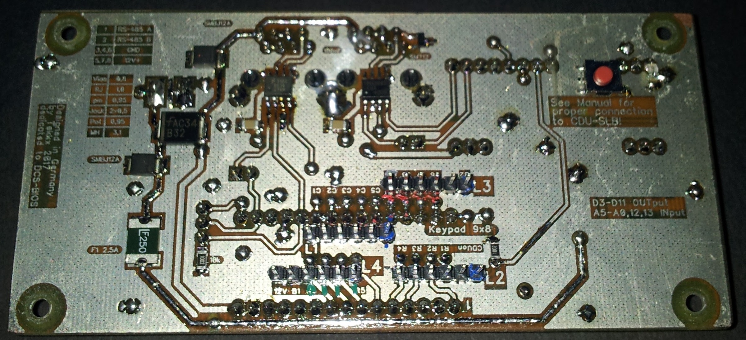
And here is the final Code. Copy and adopt it to your Requirements. Have Fun! // ****************************************************************************************** // A-10C CDU Keypad // ****************************************************************************************** // Made 11-2017 by Tekkx, based on the amazing work (called DCS-BIOS) of jboecker [FSF]Ian. // Also I want to give my gratitude to Hansolo HMA Hans. // This sketch is made for the combination of the special // - ICB-C-RJ-... (Interface- and Control-Board) and the // - CDU-SLB ... (CDU-Switch- and Light-Board) // It should run on any related hardware after some Adaptations. // There are also sketches for the Backlight and for the LCD available. // // This is the final (pending further notice) and running Version of 2017-11-05. // ****************************************************************************************** #define DCSBIOS_RS485_SLAVE 100 // adopt ID to your actual bus architecture and don't forget to put it somewhere down on paper. :) //The Arduino pin that is connected to the /RE and DE pins on the RS-485 transceiver. #define TXENABLE_PIN 2 // hard coded on PCB of ICB-C-RJ-... #include <Keypad.h> //#include <Keypad2.h> // alternative version that consumes some less memory #include <DcsBios.h> #include <Servo.h> const byte ROWS = 8; // quantity of rows (later 8) const byte COLS = 9; // quantity of columns (later 9) char keys[ROWS][COLS] = { // Define the Keymap / upper and lower cases matter, don't use ä ö ü Ä Ö Ü // D3, D4 , 5, 6, 7, 11, 10, 9, 8 {'1','2','3','4','5','6','7','8','9'}, // 12 {'0','q','w','e','r','t','z','u','i'}, // 13 {'o','p','a','s','d','f','g','h','j'}, // A0 {'k','l','(','%','#','<','y','x','c'}, // A1 {'v','b','n','m','Q','W','E','R','T'}, // A2 - R5 {'Z','U','I','O','P','A','S','D','F'}, // A3 {'G','H','J','K','L','*',')','>','Y'}, // A4 {'X','C','V','B','N','M',';',':','+'} // A5 }; // Connect Matrix Rows and Columns to these Arduino pins. // Just valid to NANO: A6 and A7 are just analog INs. Don't use them for the Matrix. byte rowPins[ROWS] = { 12, 13, A0, A1, A2, A3, A4, A5 }; byte colPins[COLS] = { 3, 4 , 5, 6, 7, 11, 10, 9, 8 }; // Create the Keypad, initialize an instance of class CDUkeys Keypad CDUkeys = Keypad( makeKeymap(keys), rowPins, colPins, ROWS, COLS ); // --------------------------- keys: name of the Matrix // ------- void setup() { DcsBios::setup(); CDUkeys.addEventListener(keypadEvent); // Add an event listener. ///THX hansolo CDUkeys.setHoldTime(100); // Default is 1000mS ///THX hansolo CDUkeys.setDebounceTime(50); // Default is 50mS ///THX hansolo } void loop() { DcsBios::loop(); char key = CDUkeys.getKey(); } void keypadEvent(KeypadEvent CDUbutton){ switch (CDUkeys.getState()) { // gives PRESSED, HOLD or RELEASED///* case PRESSED: // If you change sth. here: Don't forget the RELEASED-division down under!!! switch(CDUbutton) { // CDUbutton // following commands are fired unique if PRESSED // Row 1 - Cols 1 2 3 4 5 6 7 8 -- case '1': sendDcsBiosMessage("CDU_LSK_3L", "1"); break; // case '2': sendDcsBiosMessage("CDU_LSK_5L", "1"); break; // case '3': sendDcsBiosMessage("CDU_LSK_7L", "1"); break; // case '4': sendDcsBiosMessage("CDU_LSK_9L", "1"); break; // case '5': sendDcsBiosMessage("CDU_LSK_3R", "1"); break; // case '6': sendDcsBiosMessage("CDU_LSK_5R", "1"); break; // case '7': sendDcsBiosMessage("CDU_LSK_7R", "1"); break; // case '8': sendDcsBiosMessage("CDU_LSK_9R", "1"); break; // // case '9': No Button, no Matrix Junction! // Row 2 - Cols 1 2 3 4 5 6 7 8 case '0': sendDcsBiosMessage("CDU_SYS", "1"); break; // case 'q': sendDcsBiosMessage("CDU_NAV", "1"); break; // case 'w': sendDcsBiosMessage("CDU_WP", "1"); break; // case 'e': sendDcsBiosMessage("CDU_OSET", "1"); break; // case 'r': sendDcsBiosMessage("CDU_FPM", "1"); break; // case 't': sendDcsBiosMessage("CDU_PREV", "1"); break; // case 'z': sendDcsBiosMessage("CDU_BRT", "0"); break; // DIM/BRT left case 'u': sendDcsBiosMessage("CDU_BRT", "2"); break; // DIM/BRT right // case 'i': No Button, no Matrix Junction! // Row 3 - Cols 1 2 3 4 5 6 7 8 9 case 'o': sendDcsBiosMessage("CDU_1", "1"); break; // case 'p': sendDcsBiosMessage("CDU_2", "1"); break; // case 'a': sendDcsBiosMessage("CDU_3", "1"); break; // case 's': sendDcsBiosMessage("CDU_A", "1"); break; // case 'd': sendDcsBiosMessage("CDU_B", "1"); break; // case 'f': sendDcsBiosMessage("CDU_C", "1"); break; // case 'g': sendDcsBiosMessage("CDU_D", "1"); break; // case 'h': sendDcsBiosMessage("CDU_E", "1"); break; // case 'j': sendDcsBiosMessage("CDU_F", "1"); break; // // Row 4 - Cols 1 2 3 4 5 6 7 8 9 case 'k': sendDcsBiosMessage("CDU_4", "1"); break; // case 'l': sendDcsBiosMessage("CDU_5", "1"); break; // case '(': sendDcsBiosMessage("CDU_6", "1"); break; // case '%': sendDcsBiosMessage("CDU_G", "1"); break; // case '#': sendDcsBiosMessage("CDU_H", "1"); break; // case '<': sendDcsBiosMessage("CDU_I", "1"); break; // case 'y': sendDcsBiosMessage("CDU_J", "1"); break; // case 'x': sendDcsBiosMessage("CDU_K", "1"); break; // case 'c': sendDcsBiosMessage("CDU_L", "1"); break; // // Row 5 - Cols 1 2 3 4 5 6 7 8 9 case 'v': sendDcsBiosMessage("CDU_7", "1"); break; // case 'b': sendDcsBiosMessage("CDU_8", "1"); break; // case 'n': sendDcsBiosMessage("CDU_9", "1"); break; // case 'm': sendDcsBiosMessage("CDU_M", "1"); break; // case 'Q': sendDcsBiosMessage("CDU_N", "1"); break; // case 'W': sendDcsBiosMessage("CDU_O", "1"); break; // case 'E': sendDcsBiosMessage("CDU_P", "1"); break; // case 'R': sendDcsBiosMessage("CDU_Q", "1"); break; // case 'T': sendDcsBiosMessage("CDU_R", "1"); break; // // Row 6 - Cols 1 2 3 4 5 6 7 8 9 case 'Z': sendDcsBiosMessage("CDU_POINT", "1"); break; // case 'U': sendDcsBiosMessage("CDU_0", "1"); break; // case 'I': sendDcsBiosMessage("CDU_SLASH", "1"); break; // case 'O': sendDcsBiosMessage("CDU_S", "1"); break; // case 'P': sendDcsBiosMessage("CDU_T", "1"); break; // case 'A': sendDcsBiosMessage("CDU_U", "1"); break; // case 'S': sendDcsBiosMessage("CDU_V", "1"); break; // case 'D': sendDcsBiosMessage("CDU_W", "1"); break; // case 'F': sendDcsBiosMessage("CDU_X", "1"); break; // // Row 7 - Cols * 2 3 4 5 6 7 8 9 // case 'G': No Button, no Matrix Junction! case 'H': sendDcsBiosMessage("CDU_PG", "2"); break; // PG-Rocker up case 'J': sendDcsBiosMessage("CDU_NA1", "1"); break; // blank - No Function case 'K': sendDcsBiosMessage("CDU_NA2", "1"); break; // blank - No Function case 'L': sendDcsBiosMessage("CDU_BCK", "1"); break; // case '*': sendDcsBiosMessage("CDU_SPC", "1"); break; // case ')': sendDcsBiosMessage("CDU_Y", "1"); break; // case '>': sendDcsBiosMessage("CDU_Z", "1"); break; // case 'Y': sendDcsBiosMessage("CDU_DATA", "2"); break; // +/- Rocker up // Row 8 - Cols * 2 * 4 5 6 7 8 9 //case 'X': No Button, no Matrix Junction! case 'C': sendDcsBiosMessage("CDU_PG", "0"); break; // PG-Rocker down //case 'V': No Button, no Matrix Junction! case 'B': sendDcsBiosMessage("CDU_MK", "1"); break; // case 'N': sendDcsBiosMessage("CDU_SCROLL", "0"); break; // Scroll Waypoint-Names, Blank Rocker left case 'M': sendDcsBiosMessage("CDU_SCROLL", "2"); break; // Blank Rocker right case ';': sendDcsBiosMessage("CDU_CLR", "1"); break; // case ':': sendDcsBiosMessage("CDU_FA", "1"); break; // case '+': sendDcsBiosMessage("CDU_DATA", "0"); break; // +/- Rocker down }; break; // end case PRESSED // what break does here is a Mystery :) // without break, "RELEASED"-Code is sent immediately after pushing a button case RELEASED: switch(CDUbutton) { // following commands are fired unique if RELEASED // Row 1 - Cols 1 2 3 4 5 6 7 8 case '1': sendDcsBiosMessage("CDU_LSK_3L", "0"); break; // case '2': sendDcsBiosMessage("CDU_LSK_5L", "0"); break; // case '3': sendDcsBiosMessage("CDU_LSK_7L", "0"); break; // case '4': sendDcsBiosMessage("CDU_LSK_9L", "0"); break; // case '5': sendDcsBiosMessage("CDU_LSK_3R", "0"); break; // case '6': sendDcsBiosMessage("CDU_LSK_5R", "0"); break; // case '7': sendDcsBiosMessage("CDU_LSK_7R", "0"); break; // case '8': sendDcsBiosMessage("CDU_LSK_9R", "0"); break; // // case '9': No Button, no Matrix Junction! // Row 2 - Cols 1 2 3 4 5 6 7 8 case '0': sendDcsBiosMessage("CDU_SYS", "0"); break; // case 'q': sendDcsBiosMessage("CDU_NAV", "0"); break; // case 'w': sendDcsBiosMessage("CDU_WP", "0"); break; // case 'e': sendDcsBiosMessage("CDU_OSET", "0"); break; // case 'r': sendDcsBiosMessage("CDU_FPM", "0"); break; // case 't': sendDcsBiosMessage("CDU_PREV", "0"); break; // case 'z': sendDcsBiosMessage("CDU_BRT", "1"); break; // DIM/BRT Rocker neutral case 'u': sendDcsBiosMessage("CDU_BRT", "1"); break; // DIM/BRT Rocker neutral // case 'i': No Button, no Matrix Junction! // Row 3 - Cols 1 2 3 4 5 6 7 8 9 case 'o': sendDcsBiosMessage("CDU_1", "0"); break; // case 'p': sendDcsBiosMessage("CDU_2", "0"); break; // case 'a': sendDcsBiosMessage("CDU_3", "0"); break; // case 's': sendDcsBiosMessage("CDU_A", "0"); break; // case 'd': sendDcsBiosMessage("CDU_B", "0"); break; // case 'f': sendDcsBiosMessage("CDU_C", "0"); break; // case 'g': sendDcsBiosMessage("CDU_D", "0"); break; // case 'h': sendDcsBiosMessage("CDU_E", "0"); break; // case 'j': sendDcsBiosMessage("CDU_F", "0"); break; // // Row 4 - Cols 1 2 3 4 5 6 7 8 9 case 'k': sendDcsBiosMessage("CDU_4", "0"); break; // case 'l': sendDcsBiosMessage("CDU_5", "0"); break; // case '(': sendDcsBiosMessage("CDU_6", "0"); break; // case '%': sendDcsBiosMessage("CDU_G", "0"); break; // case '#': sendDcsBiosMessage("CDU_H", "0"); break; // case '<': sendDcsBiosMessage("CDU_I", "0"); break; // case 'y': sendDcsBiosMessage("CDU_J", "0"); break; // case 'x': sendDcsBiosMessage("CDU_K", "0"); break; // case 'c': sendDcsBiosMessage("CDU_L", "0"); break; // // Row 5 - Cols 1 2 3 4 5 6 7 8 9 case 'v': sendDcsBiosMessage("CDU_7", "0"); break; // case 'b': sendDcsBiosMessage("CDU_8", "0"); break; // case 'n': sendDcsBiosMessage("CDU_9", "0"); break; // case 'm': sendDcsBiosMessage("CDU_M", "0"); break; // case 'Q': sendDcsBiosMessage("CDU_N", "0"); break; // case 'W': sendDcsBiosMessage("CDU_O", "0"); break; // case 'E': sendDcsBiosMessage("CDU_P", "0"); break; // case 'R': sendDcsBiosMessage("CDU_Q", "0"); break; // case 'T': sendDcsBiosMessage("CDU_R", "0"); break; // // Row 6 - Cols 1 2 3 4 5 6 7 8 9 case 'Z': sendDcsBiosMessage("CDU_POINT", "0"); break; // case 'U': sendDcsBiosMessage("CDU_0", "0"); break; // case 'I': sendDcsBiosMessage("CDU_SLASH", "0"); break; // case 'O': sendDcsBiosMessage("CDU_S", "0"); break; // case 'P': sendDcsBiosMessage("CDU_T", "0"); break; // case 'A': sendDcsBiosMessage("CDU_U", "0"); break; // case 'S': sendDcsBiosMessage("CDU_V", "0"); break; // case 'D': sendDcsBiosMessage("CDU_W", "0"); break; // case 'F': sendDcsBiosMessage("CDU_X", "0"); break; // // Row 7 - Cols * 2 3 4 5 6 7 8 9 // case 'G': No Button, no Matrix Junction! case 'H': sendDcsBiosMessage("CDU_PG", "1"); break; // PG-Rocker neutral case 'J': sendDcsBiosMessage("CDU_NA1", "0"); break; // blank - No Function case 'K': sendDcsBiosMessage("CDU_NA2", "0"); break; // blank - No Function case 'L': sendDcsBiosMessage("CDU_BCK", "0"); break; // case '*': sendDcsBiosMessage("CDU_SPC", "0"); break; // case ')': sendDcsBiosMessage("CDU_Y", "0"); break; // case '>': sendDcsBiosMessage("CDU_Z", "0"); break; // case 'Y': sendDcsBiosMessage("CDU_DATA", "1"); break; // +/- Rocker neutral // Row 8 - Cols * 2 * 4 5 6 7 8 9 //case 'X': No Button, no Matrix Junction! case 'C': sendDcsBiosMessage("CDU_PG", "1"); break; // PG-Rocker neutral //case 'V': No Button, no Matrix Junction! case 'B': sendDcsBiosMessage("CDU_MK", "0"); break; // case 'N': sendDcsBiosMessage("CDU_SCROLL", "1"); break; // Scroll Waypoint-Names, Blank Rocker neutral case 'M': sendDcsBiosMessage("CDU_SCROLL", "1"); break; // Blank Rocker neutral case ';': sendDcsBiosMessage("CDU_CLR", "0"); break; // case ':': sendDcsBiosMessage("CDU_FA", "0"); break; // case '+': sendDcsBiosMessage("CDU_DATA", "1"); break; // +/- Rocker neutral } // end case RELEASED } // end switch getState() } // end void keypadEvent Here is a Dropbox-Link with some Gerbers and the Original Diptrace-Files of ICB and SLB. https://www.dropbox.com/sh/g2mfkx97mz8igxl/AAADacYudCVqoEnOyYIhzsGya?dl=0 If you encounter any kind of problem: Tell me. Diptrace-Files you can open with Diptrace Freeware Version (even the SLB exceeds the 300-Pin-Barrier) as long you do not add (or change?) anything. And here is a Link to some Photographs: https://forums.eagle.ru/album.php?albumid=1431 (No BB-Code fpr Albums?)
-
Hey Hans. As I gazed at your work I became some kind of jealous of your Original Stuff. :) Could you offer a peek under the CDU's panel? I am curious how "they" hid the Buttons, specifically those at the edge (where the CDU exceeds width of Dzus-Rails). Even it's a CDU of a C130 the construction might be similar or equal :) BTW: The Bus is named RS-485. There are Transceivers for this RS-485-Bus named MAX487. :)
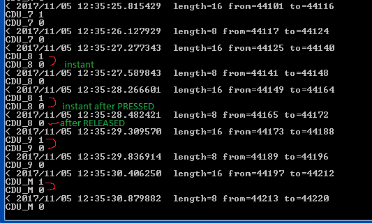
-
Learned another thing: I have a german codepage here (maybe, there's a related problem on other codepages): Don't use ä ö ü Ä Ö Ü (deutsch: Umlaute - mutated vowels) for defining the keymap. They do not work! And there is another issue: If I push a Button, it sends the Code for "PRESSED" and at the "same time" the code for "RELEASED". The effect is already to be seen at the picture in Post #6. There I blamed it to a slacky joint as I connected the Pins just with a piece of wire. I played some with debounce- and hold-timings: No difference at all. Maybe someone outthere has a clue? (I take anything as I am despaired.) (I could have solved this problem a long time ago if I ever managed to finish my MFD-Project) ;( Solved. :) I set a break; after the case PRESSED: Now it works as intended. With a little more of proficiency I could have solved this a while ago :music_whistling: And so I have no idea why it works at Hans' project without this "break;"... Mystery. ... case 'N': sendDcsBiosMessage("CDU_SCROLL", "0"); break; // Scroll Waypoint-Names, Blank Rocker left case 'M': sendDcsBiosMessage("CDU_SCROLL", "2"); break; // Blank Rocker right case ';': sendDcsBiosMessage("CDU_CLR", "1"); break; // case ':': sendDcsBiosMessage("CDU_FA", "1"); break; // case '+': sendDcsBiosMessage("CDU_DATA", "0"); break; // +/- Rocker down }; break; // end case PRESSED (button) case RELEASED: switch(CDUbutton) { // following commands are fired unique if RELEASED // Row 1 - Cols 1 2 3 4 5 6 7 8 case '1': sendDcsBiosMessage("LSK_3L", "0"); break; // case '2': sendDcsBiosMessage("LSK_5L", "0"); break; // case '3': sendDcsBiosMessage("LSK_7L", "0"); break; // case '4': sendDcsBiosMessage("LSK_9L", "0"); break; // ...
-
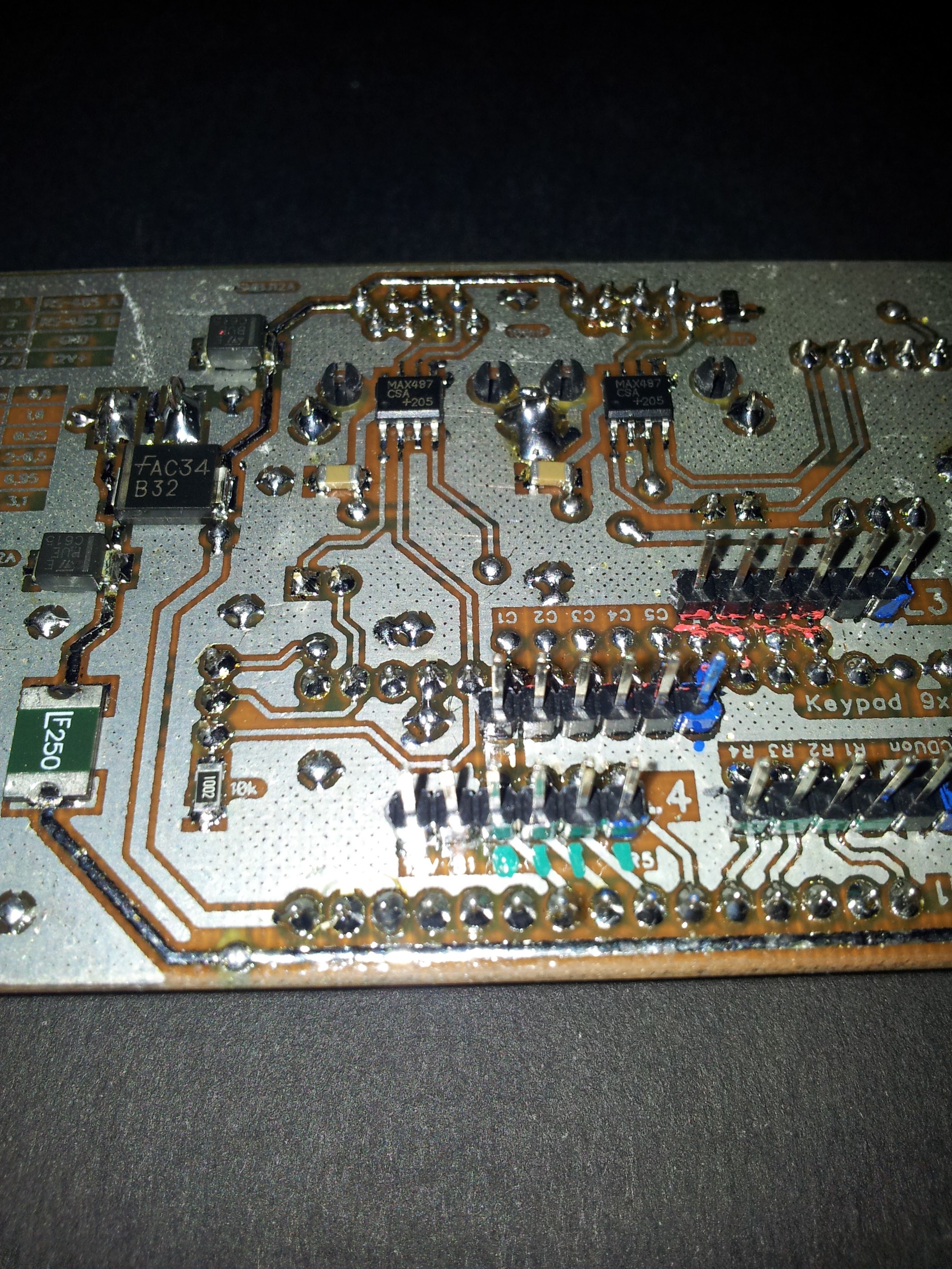
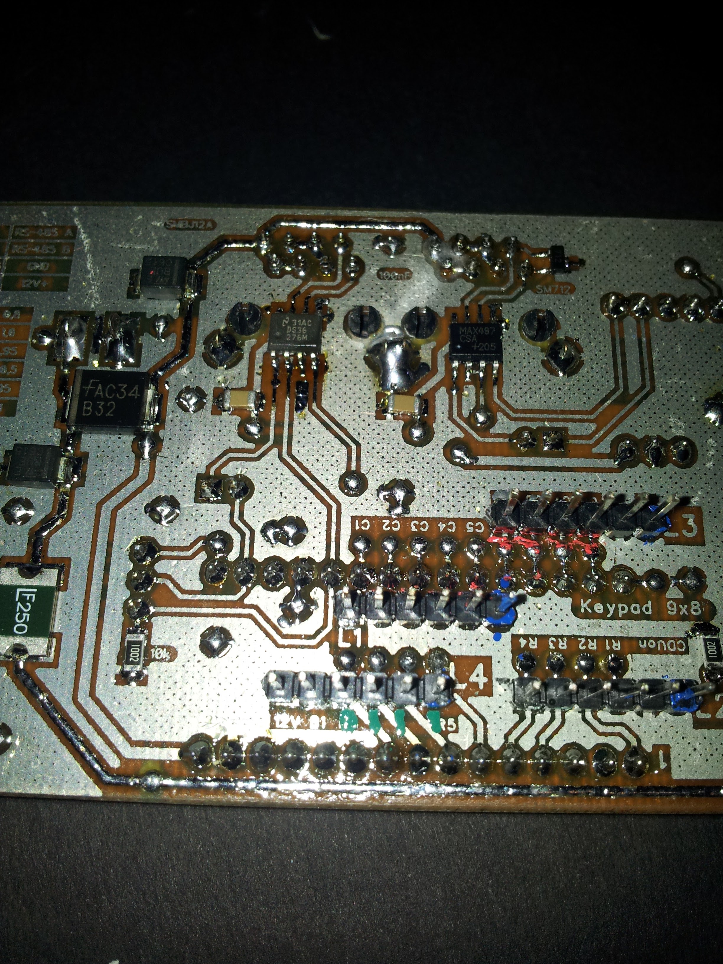
Another 30 Minutes later I found out: Roughly 80 % of my Software-Issues are based on faulty Hardware (own/house made or purchased). This is a bitter knowledge I have to live with. :( Replaced the MAX487 by a DS36276 (was the first Transceiver tumbled in my hands, MAX487 is almost the same) and it works. Now is there some fine tuning of hold- and debounce-Timing to do (as some keys do not exactly work as intended) but the Goal is in Sight. :) Here some Photographs. Before and after. :) Pay your Attention to the colored markings near of the Headers: This becomes essential, if you look for a needle in the hay-stack (shorts and gaps on the PCB) and you have to watch as one Arduino dies after his forerunner. At the top-right-bottom of the ICB you can see a Switch and a LED (LED is errected and supported by a 0805-Resistor). These are just for Troubleshooting/Testing of the RS-485: Button sends "Lamp-Test", LED represents "Master Caution"-Light. I think about to add this feature to all ICBs in the Future (if there are Pins left unused).