Tekkx
-
Posts
319 -
Joined
-
Last visited
Content Type
Profiles
Forums
Events
Everything posted by Tekkx
-
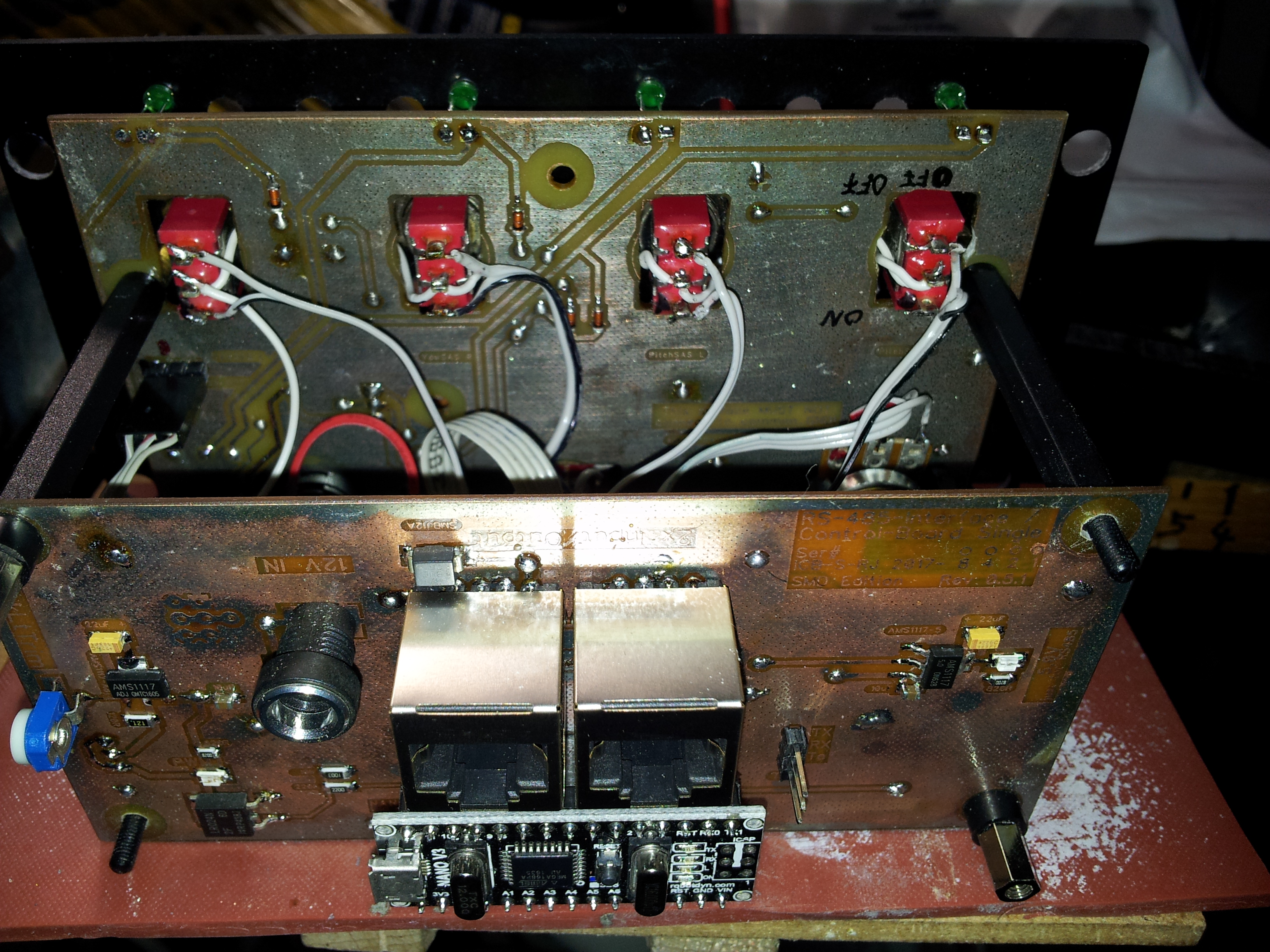
Next day's morning: My code is good, Made the test with another ICB and simulated the Keypad-Matrix with a wire to link a Row with a Column... See the Output: First (about) 10 Lines are CDU, all others are the alternative ICB. Now I have to swallow that bitter Pill: My ICB - special made for CDU - doesn't work.... I could jump arround like Rumpelstiltskin :) I set my hope on a bad MAX487... (Thank you, Hans, for this straw to clutch on) ;) BTW: Did an "investigation" on keypad and keypad2: As I have both libraries "installed", I have just to write a "2" (or not). I found no significant difference, instead keypad consumes some more Memory. Arduino-IDE gives a Warning: "Wenig Arbeitsspeicher verfügbar, es können Stabilitätsprobleme auftreten". (That's the Problem with localized software: It makes it close to impossible to communicate in the Forum) Warning means: "Short on Memory. Stability is at risk, maybe." :) First Photo: Left is the special ICB for the CDU with 2 RS-485-Transceivers and 2 Arduino NANOs. Right is a "common" ICB for general purposes like AAP or other such simple Modules.

-
Thank you, Hans, for your effort. Keypad2 is just a slightly different version of the Library (never did a deep view on it). I already changed that ... with no desired effect. Looks like I have to go thru the code (again) line by line. Somewhere there must be some "Hickup". Tomorrow I'll try another ICB (Interface- and Control-Board) and simulate the keypad with a wire bridge. Just to exclude a strange side-effect of my Switchboard. Also I will open the Library's location and have a closer look at it. So I'll understand (maybe) the intention of Lib's Author. :) :book: But now it's late. Too late. :sleep:
-
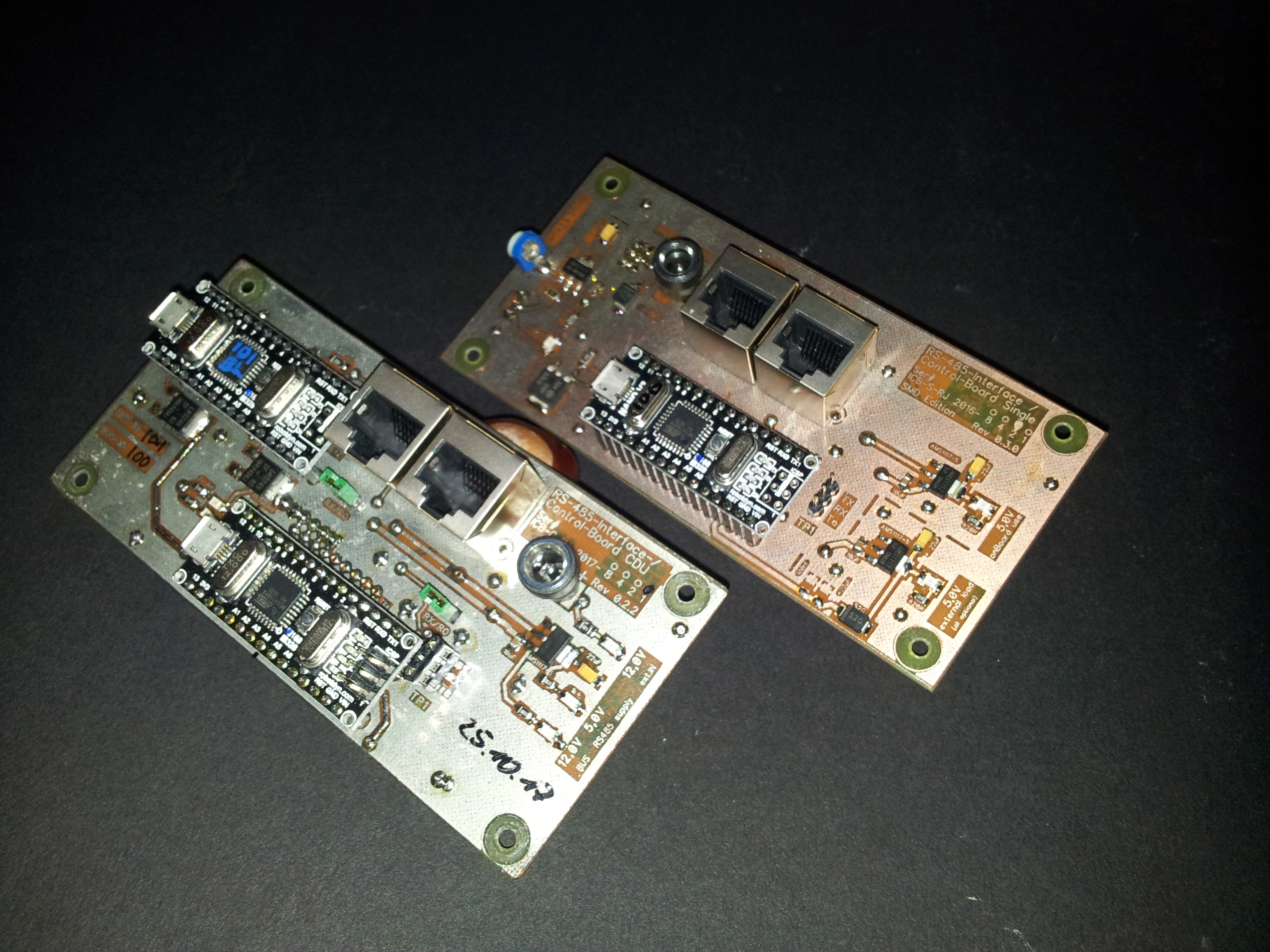
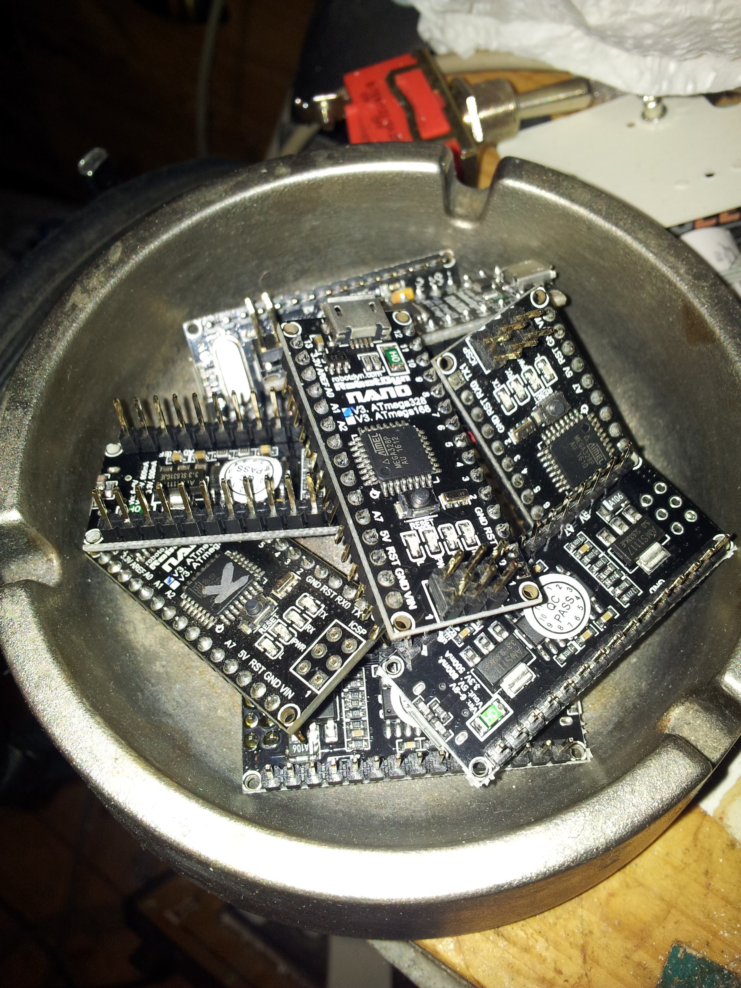
Hallo Hans (and all friends). It's a strange feeling if your code is cited somewhere in the forum and you can't (the f...n hell) bring your own work into business... (Joke ends here) :D It makes me happy (and a little bit proud), that you got your CDU running. (I gazed your Thread here: https://forums.eagle.ru/showpost.php?p=3236594&postcount=159) Mine - after solving some heavy hardware issues (some hard to find shorts on the PCB - see Photo) - spits just strange, unrelated code. Could you be so kindly to risk a short view on my code? I went (staring on it for a few hours now) blind for any errors. // ****************************************************************************************** // A-10C CDU Keypad // adopt ID to your actual bus architecture. #define DCSBIOS_RS485_SLAVE 100 // ****************************************************************************************** /* The Arduino pin that is connected to the /RE and DE pins on the RS-485 transceiver. */ #define TXENABLE_PIN 2 // hard coded on PCB #include <Keypad2.h> #include <DcsBios.h> #include <Servo.h> const byte ROWS = 8; // quantity of rows (later 8) const byte COLS = 9; // quantity of columns (later 9) char keys[ROWS][COLS] = { // Define the Keymap / upper and lower cases matter // D3, D4 , 5, 6, 7, 11, 10, 9, 8 {'1','2','3','4','5','6','7','8','9'}, // 12 {'0','q','w','e','r','t','z','u','i'}, // 13 {'o','p','a','s','d','f','g','h','j'}, // A0 {'k','l','(','%','#','<','y','x','c'}, // A1 {'v','b','n','m','Q','W','E','R','T'}, // A2 - R5 {'Z','U','I','O','P','A','S','D','F'}, // A3 {'G','H','J','K','L','Ö','Ä','>','Y'}, // A4 {'X','C','V','B','N','M',';',':','+'} // A5 }; // Connect Matrix Rows and Columns to these Arduino pins. byte rowPins[ROWS] = { 12, 13, A0, A1, A2, A3, A4, A5 }; byte colPins[COLS] = { 3, 4 , 5, 6, 7, 11, 10, 9, 8 }; // Create the Keypad, initialize an instance of class NewKeypad Keypad keypad = Keypad( makeKeymap(keys), rowPins, colPins, ROWS, COLS ); /// --------------------------- void setup() { DcsBios::setup(); keypad.addEventListener(keypadEvent); // Add an event listener. ///hansolo keypad.setHoldTime(1000); // Default is 1000mS ///hansolo keypad.setDebounceTime(200); // Default is 50mS ///hansolo } void loop() { DcsBios::loop(); char key = keypad.getKey(); ///hansolo } void keypadEvent(KeypadEvent CDUbutton){ switch (keypad.getState()) { // gives PRESSED, HOLD or RELEASED///* case PRESSED: switch(CDUbutton) { // following commands are fired unique if PRESSED // Row 1 - Cols 1 2 3 4 5 6 7 8 case '1': sendDcsBiosMessage("LSK_3L", "1"); break; // case '2': sendDcsBiosMessage("LSK_5L", "1"); break; // case '3': sendDcsBiosMessage("LSK_7L", "1"); break; // case '4': sendDcsBiosMessage("LSK_9L", "1"); break; // case '5': sendDcsBiosMessage("LSK_3R", "1"); break; // case '6': sendDcsBiosMessage("LSK_5R", "1"); break; // case '7': sendDcsBiosMessage("LSK_7R", "1"); break; // case '8': sendDcsBiosMessage("LSK_9R", "1"); break; // // case '9': No Button / Matrix Junction! // Row 2 - Cols 1 2 3 4 5 6 7 8 case '0': sendDcsBiosMessage("CDU_SYS", "1"); break; // case 'q': sendDcsBiosMessage("CDU_NAV", "1"); break; // case 'w': sendDcsBiosMessage("CDU_WP", "1"); break; // case 'e': sendDcsBiosMessage("CDU_OSET", "1"); break; // case 'r': sendDcsBiosMessage("CDU_FPM", "1"); break; // case 't': sendDcsBiosMessage("CDU_PREV", "1"); break; // case 'z': sendDcsBiosMessage("CDU_DIM", "0"); break; // DIM/BRT left case 'u': sendDcsBiosMessage("CDU_BRT", "2"); break; // DIM/BRT right // case 'i': No Button / Matrix Junction! // Row 3 - Cols 1 2 3 4 5 6 7 8 9 case 'o': sendDcsBiosMessage("CDU_1", "1"); break; // case 'p': sendDcsBiosMessage("CDU_2", "1"); break; // case 'a': sendDcsBiosMessage("CDU_3", "1"); break; // case 's': sendDcsBiosMessage("CDU_A", "1"); break; // case 'd': sendDcsBiosMessage("CDU_B", "1"); break; // case 'f': sendDcsBiosMessage("CDU_C", "1"); break; // case 'g': sendDcsBiosMessage("CDU_D", "1"); break; // case 'h': sendDcsBiosMessage("CDU_E", "1"); break; // case 'j': sendDcsBiosMessage("CDU_F", "1"); break; // // Row 4 - Cols 1 2 3 4 5 6 7 8 9 case 'k': sendDcsBiosMessage("CDU_4", "1"); break; // case 'l': sendDcsBiosMessage("CDU_5", "1"); break; // case '(': sendDcsBiosMessage("CDU_6", "1"); break; // case '%': sendDcsBiosMessage("CDU_G", "1"); break; // case '#': sendDcsBiosMessage("CDU_H", "1"); break; // case '<': sendDcsBiosMessage("CDU_I", "1"); break; // case 'y': sendDcsBiosMessage("CDU_J", "1"); break; // case 'x': sendDcsBiosMessage("CDU_K", "1"); break; // case 'c': sendDcsBiosMessage("CDU_L", "1"); break; // // Row 5 - Cols 1 2 3 4 5 6 7 8 9 case 'v': sendDcsBiosMessage("CDU_7", "1"); break; // case 'b': sendDcsBiosMessage("CDU_8", "1"); break; // case 'n': sendDcsBiosMessage("CDU_9", "1"); break; // case 'm': sendDcsBiosMessage("CDU_M", "1"); break; // case 'Q': sendDcsBiosMessage("CDU_N", "1"); break; // case 'W': sendDcsBiosMessage("CDU_O", "1"); break; // case 'E': sendDcsBiosMessage("CDU_P", "1"); break; // case 'R': sendDcsBiosMessage("CDU_Q", "1"); break; // case 'T': sendDcsBiosMessage("CDU_R", "1"); break; // // Row 6 - Cols 1 2 3 4 5 6 7 8 9 case 'Z': sendDcsBiosMessage("CDU_POINT", "1"); break; // case 'U': sendDcsBiosMessage("CDU_0", "1"); break; // case 'I': sendDcsBiosMessage("CDU_SLASH", "1"); break; // case 'O': sendDcsBiosMessage("CDU_S", "1"); break; // case 'P': sendDcsBiosMessage("CDU_T", "1"); break; // case 'A': sendDcsBiosMessage("CDU_U", "1"); break; // case 'S': sendDcsBiosMessage("CDU_V", "1"); break; // case 'D': sendDcsBiosMessage("CDU_W", "1"); break; // case 'F': sendDcsBiosMessage("CDU_X", "1"); break; // // Row 7 - Cols * 2 3 4 5 6 7 8 9 // case 'G': No Button / Matrix Junction! case 'H': sendDcsBiosMessage("CDU_PG", "2"); break; // PG-Rocker up case 'J': sendDcsBiosMessage("CDU_NA1", "1"); break; // blank - No Function case 'K': sendDcsBiosMessage("CDU_NA2", "1"); break; // blank - No Function case 'L': sendDcsBiosMessage("CDU_BCK", "1"); break; // case 'Ö': sendDcsBiosMessage("CDU_SPC", "1"); break; // case 'Ä': sendDcsBiosMessage("CDU_Y", "1"); break; // case '>': sendDcsBiosMessage("CDU_Z", "1"); break; // case 'Y': sendDcsBiosMessage("CDU_DATA", "2"); break; // +/- Rocker up // Row 8 - Cols * 2 * 4 5 6 7 8 9 //case 'X': No Button / Matrix Junction! case 'C': sendDcsBiosMessage("CDU_PG", "0"); break; // PG-Rocker down //case 'V': No Button / Matrix Junction! case 'B': sendDcsBiosMessage("CDU_MK", "1"); break; // case 'N': sendDcsBiosMessage("CDU_SCROLL", "0"); break; // Scroll Waypoint-Names, Blank Rocker left case 'M': sendDcsBiosMessage("CDU_SCROLL", "2"); break; // Blank Rocker right case ';': sendDcsBiosMessage("CDU_CLR", "1"); break; // case ':': sendDcsBiosMessage("CDU_FA", "1"); break; // case '+': sendDcsBiosMessage("CDU_DATA", "0"); break; // +/- Rocker down } // end case PRESSED (button) case RELEASED: switch(CDUbutton) { // following commands are fired unique if PRESSED // Row 1 - Cols 1 2 3 4 5 6 7 8 case '1': sendDcsBiosMessage("LSK_3L", "0"); break; // case '2': sendDcsBiosMessage("LSK_5L", "0"); break; // case '3': sendDcsBiosMessage("LSK_7L", "0"); break; // case '4': sendDcsBiosMessage("LSK_9L", "0"); break; // case '5': sendDcsBiosMessage("LSK_3R", "0"); break; // case '6': sendDcsBiosMessage("LSK_5R", "0"); break; // case '7': sendDcsBiosMessage("LSK_7R", "0"); break; // case '8': sendDcsBiosMessage("LSK_9R", "0"); break; // // case '9': No Button / Matrix Junction! // Row 2 - Cols 1 2 3 4 5 6 7 8 case '0': sendDcsBiosMessage("CDU_SYS", "0"); break; // case 'q': sendDcsBiosMessage("CDU_NAV", "0"); break; // case 'w': sendDcsBiosMessage("CDU_WP", "0"); break; // case 'e': sendDcsBiosMessage("CDU_OSET", "0"); break; // case 'r': sendDcsBiosMessage("CDU_FPM", "0"); break; // case 't': sendDcsBiosMessage("CDU_PREV", "0"); break; // case 'z': sendDcsBiosMessage("CDU_DIM", "1"); break; // DIM/BRT left case 'u': sendDcsBiosMessage("CDU_BRT", "1"); break; // DIM/BRT right // case 'i': No Button / Matrix Junction! // Row 3 - Cols 1 2 3 4 5 6 7 8 9 case 'o': sendDcsBiosMessage("CDU_1", "0"); break; // case 'p': sendDcsBiosMessage("CDU_2", "0"); break; // case 'a': sendDcsBiosMessage("CDU_3", "0"); break; // case 's': sendDcsBiosMessage("CDU_A", "0"); break; // case 'd': sendDcsBiosMessage("CDU_B", "0"); break; // case 'f': sendDcsBiosMessage("CDU_C", "0"); break; // case 'g': sendDcsBiosMessage("CDU_D", "0"); break; // case 'h': sendDcsBiosMessage("CDU_E", "0"); break; // case 'j': sendDcsBiosMessage("CDU_F", "0"); break; // // Row 4 - Cols 1 2 3 4 5 6 7 8 9 case 'k': sendDcsBiosMessage("CDU_4", "0"); break; // case 'l': sendDcsBiosMessage("CDU_5", "0"); break; // case '(': sendDcsBiosMessage("CDU_6", "0"); break; // case '%': sendDcsBiosMessage("CDU_G", "0"); break; // case '#': sendDcsBiosMessage("CDU_H", "0"); break; // case '<': sendDcsBiosMessage("CDU_I", "0"); break; // case 'y': sendDcsBiosMessage("CDU_J", "0"); break; // case 'x': sendDcsBiosMessage("CDU_K", "0"); break; // case 'c': sendDcsBiosMessage("CDU_L", "0"); break; // // Row 5 - Cols 1 2 3 4 5 6 7 8 9 case 'v': sendDcsBiosMessage("CDU_7", "0"); break; // case 'b': sendDcsBiosMessage("CDU_8", "0"); break; // case 'n': sendDcsBiosMessage("CDU_9", "0"); break; // case 'm': sendDcsBiosMessage("CDU_M", "0"); break; // case 'Q': sendDcsBiosMessage("CDU_N", "0"); break; // case 'W': sendDcsBiosMessage("CDU_O", "0"); break; // case 'E': sendDcsBiosMessage("CDU_P", "0"); break; // case 'R': sendDcsBiosMessage("CDU_Q", "0"); break; // case 'T': sendDcsBiosMessage("CDU_R", "0"); break; // // Row 6 - Cols 1 2 3 4 5 6 7 8 9 case 'Z': sendDcsBiosMessage("CDU_POINT", "0"); break; // case 'U': sendDcsBiosMessage("CDU_0", "0"); break; // case 'I': sendDcsBiosMessage("CDU_SLASH", "0"); break; // case 'O': sendDcsBiosMessage("CDU_S", "0"); break; // case 'P': sendDcsBiosMessage("CDU_T", "0"); break; // case 'A': sendDcsBiosMessage("CDU_U", "0"); break; // case 'S': sendDcsBiosMessage("CDU_V", "0"); break; // case 'D': sendDcsBiosMessage("CDU_W", "0"); break; // case 'F': sendDcsBiosMessage("CDU_X", "0"); break; // // Row 7 - Cols * 2 3 4 5 6 7 8 9 // case 'G': No Button / Matrix Junction! case 'H': sendDcsBiosMessage("CDU_PG", "1"); break; // PG-Rocker up case 'J': sendDcsBiosMessage("CDU_NA1", "0"); break; // blank - No Function case 'K': sendDcsBiosMessage("CDU_NA2", "0"); break; // blank - No Function case 'L': sendDcsBiosMessage("CDU_BCK", "0"); break; // case 'Ö': sendDcsBiosMessage("CDU_SPC", "0"); break; // case 'Ä': sendDcsBiosMessage("CDU_Y", "0"); break; // case '>': sendDcsBiosMessage("CDU_Z", "0"); break; // case 'Y': sendDcsBiosMessage("CDU_DATA", "1"); break; // +/- Rocker up // Row 8 - Cols * 2 * 4 5 6 7 8 9 //case 'X': No Button / Matrix Junction! case 'C': sendDcsBiosMessage("CDU_PG", "1"); break; // PG-Rocker down //case 'V': No Button / Matrix Junction! case 'B': sendDcsBiosMessage("CDU_MK", "0"); break; // case 'N': sendDcsBiosMessage("CDU_SCROLL", "1"); break; // Scroll Waypoint-Names, Blank Rocker left case 'M': sendDcsBiosMessage("CDU_SCROLL", "1"); break; // Blank Rocker right case ';': sendDcsBiosMessage("CDU_CLR", "0"); break; // case ':': sendDcsBiosMessage("CDU_FA", "0"); break; // case '+': sendDcsBiosMessage("CDU_DATA", "1"); break; // +/- Rocker down } // end case RELEASED } // end switch getState() //Serial.println(CDUbutton); } // end void keypadEvent RS485-Bus is running fine. Other modules (AAP and SAS) and the second NANO onboard (as I ran out of Pins, I put a second NANO here just for 2x Backlight and CDU on/off) are doing what is intended. Screenshot is done while DCS is paused. I press and release some different Buttons. It looks like they send different but irrelevant code. Fotograph shows Boneyard of NANOs. They went there while I was searching a short on board inside the button-matrix. Finally I found it: 12 V (from Backlight) touched sometimes(! that's why so hard to find)) Row 5 and grilled this way the Atmega.
-
Dear Community :) The task is to read out a Keypad Matrix and send these data to DCS by RS-485-Bus. The short way to ask my question is: Can I still use the sendDcsBiosMessage-Command? If "NO": Is there a workaround? The whole story so far: These days I'm on the last steps finalizing my actual project: CDU of the A-10C, connected to DCS without Monitor-Export by VGA. The whole thing is linked by DCS-BIOS and RS-485. As I work at DCS and DCS-BIOS intermittent, I never reach sth like routine and I forget something from time to time. The Problem (maybe I need just a little poke): In a previous project (MFD) I already used a Keypad-Matrix and it is advisable to use a Keypad Matrix at the CDU also. But: Meanwhile has something changed. As I used sth like sendDcsBiosMessage("CDU_A", "1"); if a Button was depressed, "sendDcsBiosMessage"-Command seems to be obsolete meanwhile (as I can't find it in the control-reference anymore). There is instead this: DcsBios::Switch2Pos cduA("CDU_A", PIN); As I have a Matrix here, operating with a Pin # is not helpful. Also: The MFD-Project was connected by DCSBIOS_IRQ_SERIAL. The CDU should use RS-485. As the hardware isn't 100% ready made, I did not made (and can't make) any tests at the moment. I ask just to be prepared and I want upload working code to the AVR at the first attempt as I'm not sure if my hardware is 100% operable :) For your information have a look at this code fragment: #define DCSBIOS_RS485_SLAVE 100 ... char CDUbutton[ROWS][COLS] = { // Define the Keymap / upper and lower cases matter // D3, D4 , 5, 6, 7, 11, 10, 9, 8 {'1','2','3','4','5','6','7','8','9'}, // 12 {'0','q','w','e','r','t','z','u','i'}, // 13 {'o','p','a','s','d','f','g','h','j'}, // A0 {'k','l','(','%','#','<','y','x','c'}, // A1 {'v','b','n','m','Q','W','E','R','T'}, // A2 {'Z','U','I','O','P','A','S','D','F'}, // A3 {'G','H','J','K','L','Ö','Ä','>','Y'}, // A4 {'X','C','V','B','N','M',';',':','+'} // A5 }; // Connect Matrix Rows and Columns to these Arduino pins. byte rowPins[ROWS] = { 12, 13, A0, A1, A2, A3, A4, A5 }; byte colPins[COLS] = { 3, 4 , 5, 6, 7, 11, 10, 9, 8 }; // Create the Keypad, initialize an instance of class NewKeypad Keypad CDUkeypad = Keypad( makeKeymap(CDUbutton), rowPins, colPins, ROWS, COLS ); /// --------------------------- void keypadEvent(KeypadEvent CDUbutton){ switch (CDUkeypad.getState()) { // gives PRESSED, HOLD or RELEASED case PRESSED: switch(CDUbutton) { // following commands are fired unique if PRESSED // Row 1 - Cols 1 2 3 4 5 6 7 8 case '1': sendDcsBiosMessage("LSK_3L", "1"); break; // case '2': sendDcsBiosMessage("LSK_5L", "1"); break; // case '3': sendDcsBiosMessage("LSK_7L", "1"); break; // case '4': sendDcsBiosMessage("LSK_9L", "1"); break; // case '5': sendDcsBiosMessage("LSK_3R", "1"); break; // case '6': sendDcsBiosMessage("LSK_5R", "1"); break; // case '7': sendDcsBiosMessage("LSK_7R", "1"); break; // case '8': sendDcsBiosMessage("LSK_9R", "1"); break; // ... void setup() { DcsBios::setup(); } void loop() { DcsBios::loop(); } If the thing is finally working, I upload complete paperwork (design- and code-files) here. Meanwhile you can watch the progress here: https://forums.eagle.ru/album.php?albumid=1431 Stay tuned, I upload new Photos as I took new ones. Thank you for your interest and your help also :)
-

Track replay is bugged...
Tekkx replied to Aries's topic in Release Version Bugs and Problems (Read only)
Not easy to replay a fancy Fly-By if you stuck at the meadow. :) -
Spitfire first take-off; first "landing" observations
Tekkx replied to beagleRampant's topic in DCS: Spitfire L.F. Mk. IX
This clip is very nice to watch. :) The sound is (partially) impressive thow it covers the voice-over to make it hard to understand (to a foreigner). But the lack on this video is, the most interesting things are happen outside of the frame or are cut (in the most suspenseful moment) to show another take from another position. Knowing, this wasn't the intention of this Video, I was interested in the Rudder- and Aileron-Work. This is just a few split seconds to be seen. Disappointed. -
Alternative Bus-Transceiver found Hallo, Community. I have to make a small announcement: By accident I found an alternative Transceiver for our RS-485-Bus. Some of you will already know, but I have to tell the story to the others. :) While troubleshooting my existing system (means: reading of "some" paperwork across the internet) I found the Texas Instruments DS36276. They promote it as Failsafe Multipoint Transceiver. Exactly what we need. So I ordered some of these, and what is to tell: They work like a charm. It's 100% pin- and voltage-compatible to the Max487. So you can use your old PCBs and even a mixed system (as I have it here) is no problem. OK. I brought it to life at the same time as Ian commited his dcs-bios-v0.5.5 and maybe the success is just to honor to him. But if your hands closer to the DS36276 as to the MAX487 it will be a good choice. I have a DCS-BIOS Master hanging arround here, running 24/7 for about 15 days (says Task-Manager) now. Plugged and unplugged the Bus-(Slave)Modules uncounted times and it is still running. What a joy.
-
The "void"-command starts a function or procedure. (see the manual of C++) In your example you can do "something" with the value of the variable "newValue". newValue will change if you turn the ARC Volume Pot inside the virtual cockpit. As I have no MIG, I have no idea of the meaning :) Maybe, you choose a bad example. I (just for example) use "void" to control the Backlight of my panels (A-10C) (it uses the variable "alt"): void onLcpConsoleChange(unsigned int alt) { // "alt" will get new value if Backlight changes analogWrite(PIN, alt/256); // alt = 0...65535 (could also use map()...), PIN is a PWM-OUT of the Arduino } DcsBios::IntegerBuffer lcpConsole(0x1150, 0xffff, 0, onLcpConsoleChange); In general you should reach your goals if you use the code snippets are shown in "Simple View" of control reference. You did a very nice first step with your Panel. Congratulations :) From what I know (and can see in your code and pics), your panel should work. I don't know if I have the procuration for this (cause I'm not one of the brightest candles on top of this cake): Welcome to the Pit-Builder's Community. :) PS: In the future embed your code into code-tags. It's a mess to download an example (just to dip into it) from dropbox ;) Edit: To answer your next post (without open another one): I made good experiences with those tiny momentary buttons (looked at aliexpress for the english expression) called tactile push buttons. They do not bounce and used to be very safe. (This is adressed to anyone): For discussing problems of a special nature: open a new thread. Start the Title with "DCS-BIOS... " (as Ian and Warhog asked for a few times). "DCS-BIOS: What kind of hardware is recommended (or not) for sth." could be a good template to a title. Otherwise it gets some confusing here, even a question can get lost. (Look at the number of this post) :)
-
Spitfire first take-off; first "landing" observations
Tekkx replied to beagleRampant's topic in DCS: Spitfire L.F. Mk. IX
So I think, there goes something wrong: ;) From my point of view is Taking Off the hard (but manageable) part and Landing without taking (heavy) damage is close to impossible. My Spit behaves at less than 110 knots like a drunken horse. No matter if Flaps down or not. :joystick: The only way (for me) to bring it down is a very long and straight approach. A short curved approach - as sometimes suggested in tutorials - is a thing I can't think about. -
Spitfire first take-off; first "landing" observations
Tekkx replied to beagleRampant's topic in DCS: Spitfire L.F. Mk. IX
Thank you, Klem. This looks like an amazing piece of tinker-art. Now we drift Off Topic, but just one comment: I have my old X52 here somewhere in a box. You made me think about to rape this thing instead to resell it :) I read about 5-turn pots somewhere. Think this could be a good choice. I use ATM RTY 3 and 4 of my X55 for Trim. I have to stop breathing while adjusting them. Breake a leg! -
Spitfire first take-off; first "landing" observations
Tekkx replied to beagleRampant's topic in DCS: Spitfire L.F. Mk. IX
Hey Klem. Does this mean, you ripped your X52? Or did you build your own controller? (very interested to see that) And regarding the workload you mentioned: I think(!) to spin the trim-wheels inside the real bird produces some nice blisters on your left hand palm in the course of a hard day with T/O and Landing-Training. :) -
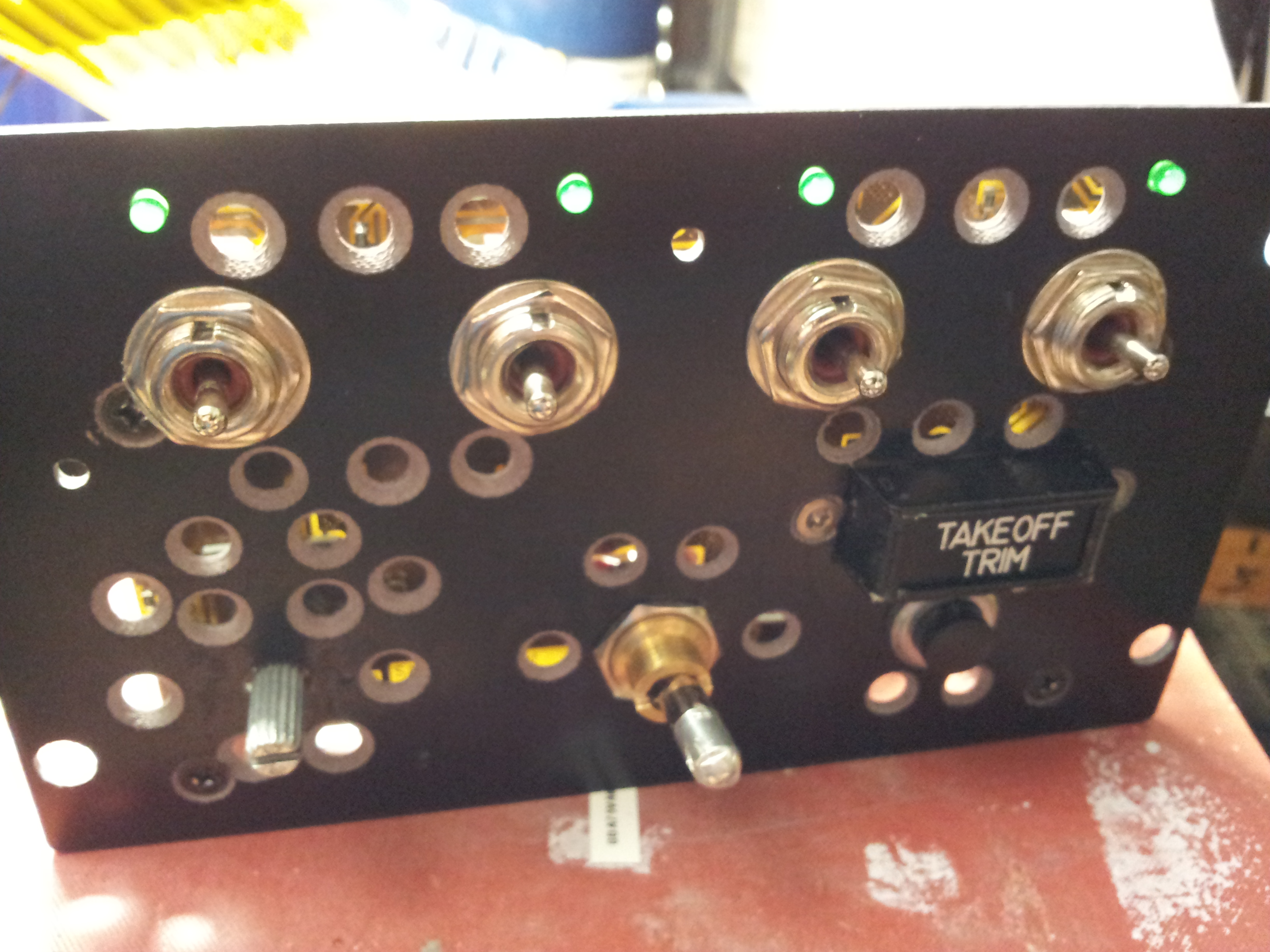
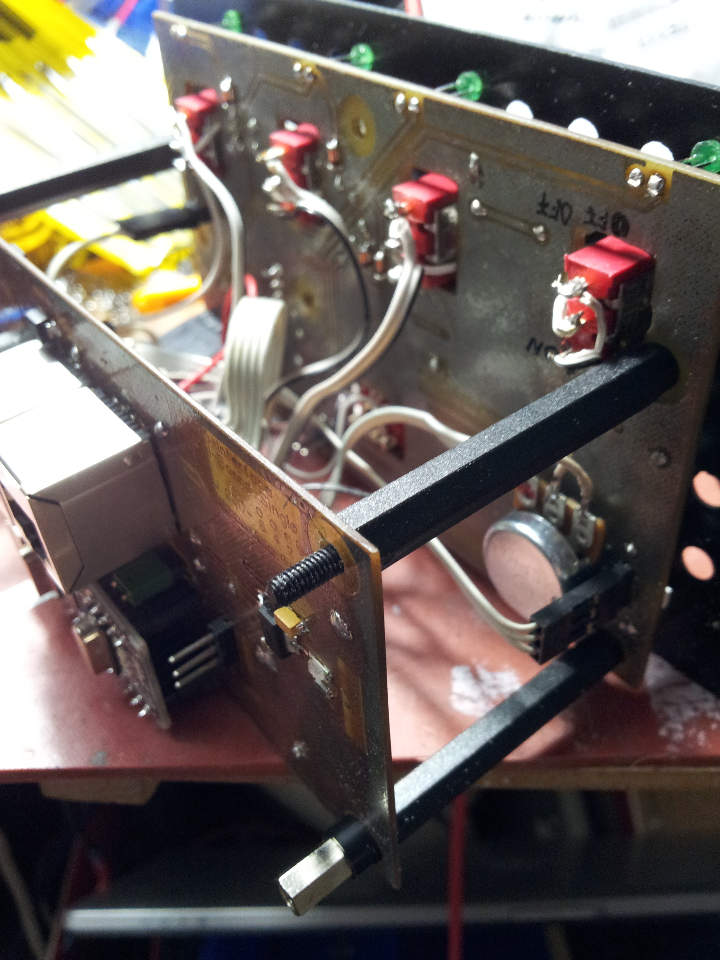
Now has risen the next problem (as usual): As my Pot has a detention at center (while the physical center isn't equal to the electrical center) I have to add some kind of Trim-(of the TRIM)-feature. If the TRIM pot (due to the retention point) isn't at precise center position, TAKEOFF TRIM doesn't work. I think about to add a second pot as a trimmer to evoke a slight shifting of the electrical center to match the mechanical center. I have no adequate hardware available, but a dry calculating experiment shows, a Threaded Potentiometer (Trimmer) with about (or some more) 2 MOhm (soldered parallel to all 3 pins of the 10k-Pot) should do the job. Edit (few days later): A 2MOhm 10turn-Trim-Potentiometer has been delivered (to prevent mistakes I'll call it from now "Shift-Pot" or "Center-Shift-Pot"). I soldered it (quick and dirty) Pin-on-Pin on the YAW-TRIM Pot: As I supposed: I can shift the center of the YAW-TRIM as I want. The Range of the TRIM-Pot (0 to 65534) is the same as before. The tuning procedure is as follows: - Establish a working RS-485-System with running connect-serial-port.cmd-window (I use the ASK-variant, which is very reliable - Thank You, Ian). DCS is in PAUSE or even not started. - Calculate the center of the pot (65534 / 2) (mental or use a pocket calculator) ;) - Bring YAW_TRIM to the mechanical center - Turn Center-Shift-Pot (while watching your command-window) until you reach the calculated value (or a value close to this). That's it. To move the center I have to do some (at least one or two) turns at the Shift-Pot. Very convinient and precise. No Breath Holding while shifting is needed. :) Success! Roll-Out-Version of this Light-Board will have this Shift-Pot on board as a standard feature and will be ready tuned. Look at the pic: This is what I describe as "quick-n-dirty" :) For a better view I unplugged the Backlight (3pin connector, labeled "PWM in", which comes from the Interface-Control-Board).
-
Oh. Dammit. I took a closer look and found out, I installed v0.2.11 already, but I unzipped it not yet. So I found at my storage just this old directory. :music_whistling: Ergo my laudatio is regarding 0.2.11 and dcs-bios-v0.5.5 :thumbup: I will modify my code tomorrow. :) And: You aren't late! Good luck for your applications. Edit: While I opened this thread and complained about jitter, the compiled and uploaded version on the used NANO has been at least six months old and still at v0.2.6. Updating with the latest library solved the problem well (even with plain Potentiometer class) :) BTW this tells me, I (we) have to have a closer look to new updates. This should be standard procedure, as you (Ian) put a lot of work and knowledge in it. Shame on me!
-
After a long time I found some spare to continue the work on my cockpit parts. I'm still on the SAS-Panel. Just as it looked like it should work, I encountered a new problem: TRIM-pot stutters! It's a special pot with a detention at center position, it feels very well and it was not some cheap. The matter is, it sends a continuous data stream to DCS, except on both end positions. BTW: Thank you, Ian, for the latest version of dcs-library 0.2.6. Looks (out from my actual position) like any connection problems of the past will stay there: In the Past. Great work. Thank you. Search and Read this forum regard stutter brought nothing useful out. So I sat down here and raped Ians library. Before I go to the testbed and brick my system I want to show my thoughts here to discuss them: (There is a close-to-100%-chance I haven't noticed some side effects) Here's my version of Potentiometers.h #ifndef __DCSBIOS_POTS_H #define __DCSBIOS_POTS_H #include "Arduino.h" #include "PollingInput.h" namespace DcsBios { class Potentiometer : PollingInput { private: void pollInput() { unsigned int state = map(analogRead(pin_), 0, 1023, 0, 65535); // if (state != lastState_) { // original line // replaced by following two lines int valueChange = abs(state - lastState_); // declares absolut change if (valueChange > 500) { // sends message just if Pot has really changed its value (500 is just shot from the hip, maybe much less will do the job) char buf[6]; utoa(state, buf, 10); if (sendDcsBiosMessage(msg_, buf)) lastState_ = state; } } char* msg_; char pin_; unsigned int lastState_; public: Potentiometer(char* msg, char pin) { msg_ = msg; pin_ = pin; pinMode(pin_, INPUT); lastState_ = map(analogRead(pin_), 0, 1023, 0, 65535); } }; } #endif Feel free to bash or/and improve my thoughts.
-
Hey, Mr. Burns. You are right. It's wrong here :) But I'll answer anyway: Based on what I understand your way (adding pins to get more outputs) will not work. But you can use the original arduino keypad library. I started to realize two MFDs with just one NANO. Also a CDU keypad is possible (not with the same NANO at same time). As I remember right now, I contributed my (not finished yet) code-fragment already here: https://forums.eagle.ru/showpost.php?p=2916918&postcount=19 The code-example shows the way to build an 8x9-Matrix. Don't forget to include Diodes into your Matrix's Layout (if you intend to press more than one button at same time). If I find some time for that, I should post a tutorial somewhere here.... :book: Meanwhile the manual of this library should help. Otherwise: Thanks to DCS-BIOS we can connect an almost unfinite number of NANOs to DCS. So there are just a few special cases where a keypad makes sense.
-
Hallo Friends. Due to other problems here (in real life) I missed this thread. Found it accidential this morning. :) Just a short post, as I have to go to work next minutes. I'm on a modular system, consisting of Master-Shield to set on a MEGA. It provides three channels of RS-485-Bus a common (Slave) Interface-Control-Board (ICB) which brakes out one (1) Arduino NANO - for use in most Panels some different specialized Slave-ICBs, which brake out one or more (ATM up to 4) NANOs (one of them is to connect a TFT for e.g. CDU) different Light-Boards (e.g. SAS, AAP) I target on Pit-Builders, they don't can (or want) convert their flat into a workshop. Everything is on a prototyping status. I think ATM, I can roll out a first batch this year. The whole system (so is my intention) should be ready-to-use (do not confuse with RTF!) and bullet-proof. All boards provides Fail-Safe features, power supply and easy connecting. So any Pit-Builder can connect them (nearly) solderless. For all those who interested and live too far away from Germany I'll commit all data to the community (as soon as I'm sure it works perfect). @Gadroc: Thank you for your compilation of data.
-
This is the key. Thank you, Ian. (Good to know, you are always here :) ) Now, as I read your lines, I remember I scanned similar somewhere before... And here is the code: /* The following #define tells DCS-BIOS that this is a RS-485 slave device. It also sets the address of this slave device. The slave address should be between 1 and 126 and must be unique among all devices on the same bus. */ // ****************************************************************************************** // A-10C SAS // adopt ID to your actual bus architecture. #define DCSBIOS_RS485_SLAVE 20 // ****************************************************************************************** /* The Arduino pin that is connected to the /RE and DE pins on the RS-485 transceiver. */ #define TXENABLE_PIN 2 // hard coded on PCB #define consoleBltPin 3 // PWMout for controlling Backlite, hard coded on Tekkx' ICB #include "DcsBios.h" // modified variable by deleting "p" (for panel) const byte saspYawSasLPins[2] = {A6,A5}; DcsBios::SwitchMultiPos sasYawSasL("SASP_YAW_SAS_L", saspYawSasLPins, 2); DcsBios::LED saspYawSasL(0x1108, 0x0400, 4); const byte saspYawSasRPins[2] = {A4,A3}; DcsBios::SwitchMultiPos sasYawSasR("SASP_YAW_SAS_R", saspYawSasRPins, 2); DcsBios::LED saspYawSasR(0x1108, 0x0800, 5); const byte saspPitchSasLPins[2] = {A2,A1}; DcsBios::SwitchMultiPos sasPitchSasL("SASP_PITCH_SAS_L", saspPitchSasLPins, 2); DcsBios::LED saspPitchSasL(0x1108, 0x1000, 6); const byte saspPitchSasRPins[2] = {9,10}; DcsBios::SwitchMultiPos sasPitchSasR("SASP_PITCH_SAS_R", saspPitchSasRPins, 2); DcsBios::LED saspPitchSasR(0x1108, 0x2000, 7); DcsBios::Potentiometer saspYawTrim("SASP_YAW_TRIM", A7); DcsBios::Switch3Pos saspMonitorTest("SASP_MONITOR_TEST", 11,12); DcsBios::LED takeOffTrim(0x1026, 0x0400, 8); DcsBios::Switch2Pos saspToTrim("SASP_TO_TRIM", 13); void setup() { DcsBios::setup(); } void loop() { DcsBios::loop(); } // Backlight Control void onLcpConsoleChange(unsigned int alt) { analogWrite(consoleBltPin, alt/256); // alt = 0...65535 (could also use map()...) } DcsBios::IntegerBuffer lcpConsole(0x1150, 0xffff, 0, onLcpConsoleChange);
-
As time went by (meanwhile) I realized a cheap (not really cheap but also not quick and dirty) solution without the use of MHS (You'll remember: Magnetic Hold Switch). I use a simple (ON)-OFF-(ON) switch and report the state of the SAS channel to the pilot by a LED. As I coded the sketch (coding means - thanks to Ian - dully copy and paste of code snippets) I encountered a problem. Maybe it is solved meanwhile somewhere sometime. I searched the forum, but I doesn't manage to find it: ... const byte saspYawSasLPins[2] = {A6,A5}; DcsBios::SwitchMultiPos saspYawSasL("SASP_YAW_SAS_L", saspYawSasLPins, 2); DcsBios::LED saspYawSasL(0x1108, 0x0400, 4); ... Complete code I'll post if this problem is solved. Compiling gives the error "conflicting declaration" 'DcsBios::LED saspYawSasL' Which makes sense to me. My concept forces the use of SwitchMultiPos and the LED. (LEDs state symbolizes the switchs state of the SAS channel). I attached two photos of my skeletton. There aren't the final switch-levers yet. The crater-like holes are for the backlite. Lightplate is not mounted yet. On top you see the 4 Status-LEDs. While I spent last months with these mechanical details I lost some of my knowledges about DCS-BIOS. Is there someone with a helpful hint?
-
Spitfire first take-off; first "landing" observations
Tekkx replied to beagleRampant's topic in DCS: Spitfire L.F. Mk. IX
I can't recognize your problem :) Your video shows a remarkable circuit - much better than my best I ever managed. But I remember my first steps with the Spitfire, just taxi ("taxi" is another word for "try to get off the meadows back to the concrete"). The next day after this first trials I've had heavy aching muscels in my ass cheek (just one side). -
Track replay is bugged...
Tekkx replied to Aries's topic in Release Version Bugs and Problems (Read only)
Exactly my thoughts yesterday night. But than I remember I watched me flying a short trip - just about 40 miles airport to airport - and my A-10C landed about 100 meters besides the strip (going up in flames). This was a very ancient version about two years ago. :doh: I blamed it to a sloppy adjusted GPS (I was not aware about those things). -
Track replay is bugged...
Tekkx replied to Aries's topic in Release Version Bugs and Problems (Read only)
Yesterday I took my Spitfire out for a ride. I managed two dangerous looking take offs and also two (similar looking) landings with no major damage. This procedure took around 45 minutes (as I wrote to my Flight Book). Replay ran fine until the second landing as I taxi the short way in the meadow :) Up to this point I blamed the unexpected well behave of the Track-Replay to the latest update but than I became disappointed. In "real life" I reached my parking area in good order, in Replay my bird stuck. I sat here and watched "me" actuating rudder and throttle (same or similar?) as I did before but the plane stuck (maybe in a molehill that there wasn't before). The plane came free as I gave full throttle for a second to perform a 180 degrees turn at parking pod while recording. In replay it made just a short move forward. What a shame! -
Track replay is bugged...
Tekkx replied to Aries's topic in Release Version Bugs and Problems (Read only)
Agreed also. :thumbup: So why it works sometimes(!) and mostly it doesn't? About 40 percent of fun is generated by watching my progresses (to raise my ego) and observing my fails (to learn on that - maybe). Conclusion: I've paid (all in all) about 100 $ too much for it. Still hoping for a bug fix. :music_whistling: -
Thank you Gus, for your efforts. I'm shure you'll share if you find something useful out :) Similar here :/ So it happens I push some matters noteless to the siding: E.g. my brandnew laser-cutter is still unpacked in it's card-box for half a year consuming place and catching dust. Not even I know if there is really a laser-cutter inside :doh: Hold on and tell us about. So I'll do.
-
The problem could accrue, if you - pushing the button - miss the delay. Once the coil is fired, DCS can't differ, if YOU press the Switch or DCS its self - HW-switch is the same status: ON. So the Switch (physical and virtual ones) will stay in ON position, no matter if SAS (or other switched device) is ON or OFF. Don't know, how it works in the real bird, but if I hold a button (or momentary switch) in the ON position, it will be in the ON position as long as I press my finger on it. No matter if there is a current or voltage on the line. It looks really like the only working way is to request this feature (export coil-status) from ED. Or we have some hackers slob out here :music_whistling:
-
Good morning Gus. Meanwhile I did some thinking and (just think) I found a solution. Owners of MagneticHoldSwitches (following called: MHS) won't be amused by that. Attached is what I squeezed out of my brain this morning at the kitchen table, consuming 3 pots of coffee and about 5 cigarettes, before I woke up my little girl (meanwhile I sit at work): We need a special MHS which can execute 3 conditions: 1. Lever in OFF-position 2. Lever in halfON-position (explanation follows) 3. Lever in ON-position This description should work on any/all MHS in the A-10C. - Pilot actuates Hardware MHS, lever has to pushed into ON (T1 closed). - if DCS accepts ON: coil is fired and holds lever in halfON, T1 opens if pilot releases lever, DCS holds still at halfON. Inside Sim the lever stays at ON position - if pilot decides to switch lever to OFF: DCS recognizes and releases coil. - if DCS declines status ON: coil is fired as long pilot holds lever in ON. As pilot releases lever, lever will follow releasing finger until halfON position, T1 opens, DCS no longer sustains condition ON, coil is no longer fired, lever falls back to OFF. Zack fertich. T0 is closed, if MHS is coil-actuated. No further action required (I think so). My example works, if we use following code: const byte saspPitchSasLPins[2] = {PIN_0, PIN_1}; DcsBios::SwitchMultiPos saspPitchSasL("SASP_PITCH_SAS_L", saspPitchSasLPins, 2); DcsBios::LED saspPitchSasL(0x1108, 0x1000, PIN_3); Pin_0 is connected to T2 at my sketch Pin_1 is connected to T1 Pin_3 is connected to the coil (LED) with adequate amplification (MOSFET or Darlington) I could act out some more examples.... I think it's clear. To reach an almost true-to-life situation, Lever-Stages ON and halfON should be as close as possible. Lever's tip shouldn't move more than 2 mm back after "removing" your finger off the lever (down-left corner of my sketch). Your fourth option (a request to ED) is still subject to discuss :)