DeadMeat
-
Posts
171 -
Joined
-
Last visited
Content Type
Profiles
Forums
Events
Everything posted by DeadMeat
-

DCS-BIOS F/A-18C library. Get it here!
DeadMeat replied to Bullant's topic in Controller Questions and Bugs
Update looks good. A small nitpick - looks like you missed the LTexture and RTexture outputs for the IFEI (the small L and R that show up next to fuel quantities in QTY sub modes). Something to consider for your next update.. -
Table mounted landing gear selector switch from a Tornado
DeadMeat replied to DeadMeat's topic in Home Cockpits
The gear switch assembly is basically just a mechanism that throws a bunch of toggle switches when you move the handle up or down. I've put LEDs in the handle that light up in place of the little lamps there were there originally and they're wired through the handle and out the back along with the toggle switches. So...the wiring is very straightforward and follows exactly how you would wire any toggle switch and any LED to any Arduino board. I strongly recommend that you follow Ian's tutorial to learn how to do exactly that and how to use the DCS BIOS code as well: http://dcs-bios.a10c.de/docs/v0.7.0/userguide.html It shows an example for an Uno and the A-10C module but the principle works for any board and any module, including the Nano and the F/A-18C. If you want to learn about how to control a solenoid I recommend that you check out Hansolo's thread or GSS Rain's excellent videos, like . The guys are dealing with MAG switches, but since these also contain a solenoid the same MOSFET solution applies. Note that you can get away with using 12V in many cases. -
Table mounted landing gear selector switch from a Tornado
DeadMeat replied to DeadMeat's topic in Home Cockpits
Thanks for the comments guys. The setup is still working great after a few weeks of use. I bought another gear switch from this guy to convert into a hook switch: https://www.ebay.com/itm/RAF-Aircraft-Undercarriage-Selector-Switch-as-fitted-to-Tornado-Aircraft/223124835190 He only has one more left if anyone's interested, but then there's many similar switches to be found, e.g. https://www.ebay.com/itm/Aircraft-ZE158-1986-Panavia-Tornado-F-3-Undercarriage-U-C-Selector-Switch-K0653/223155655591 This model seems to be quite common. It is a little different from the one I have and I can't make out if the two little holes on the end is supposed to light up during operation. -
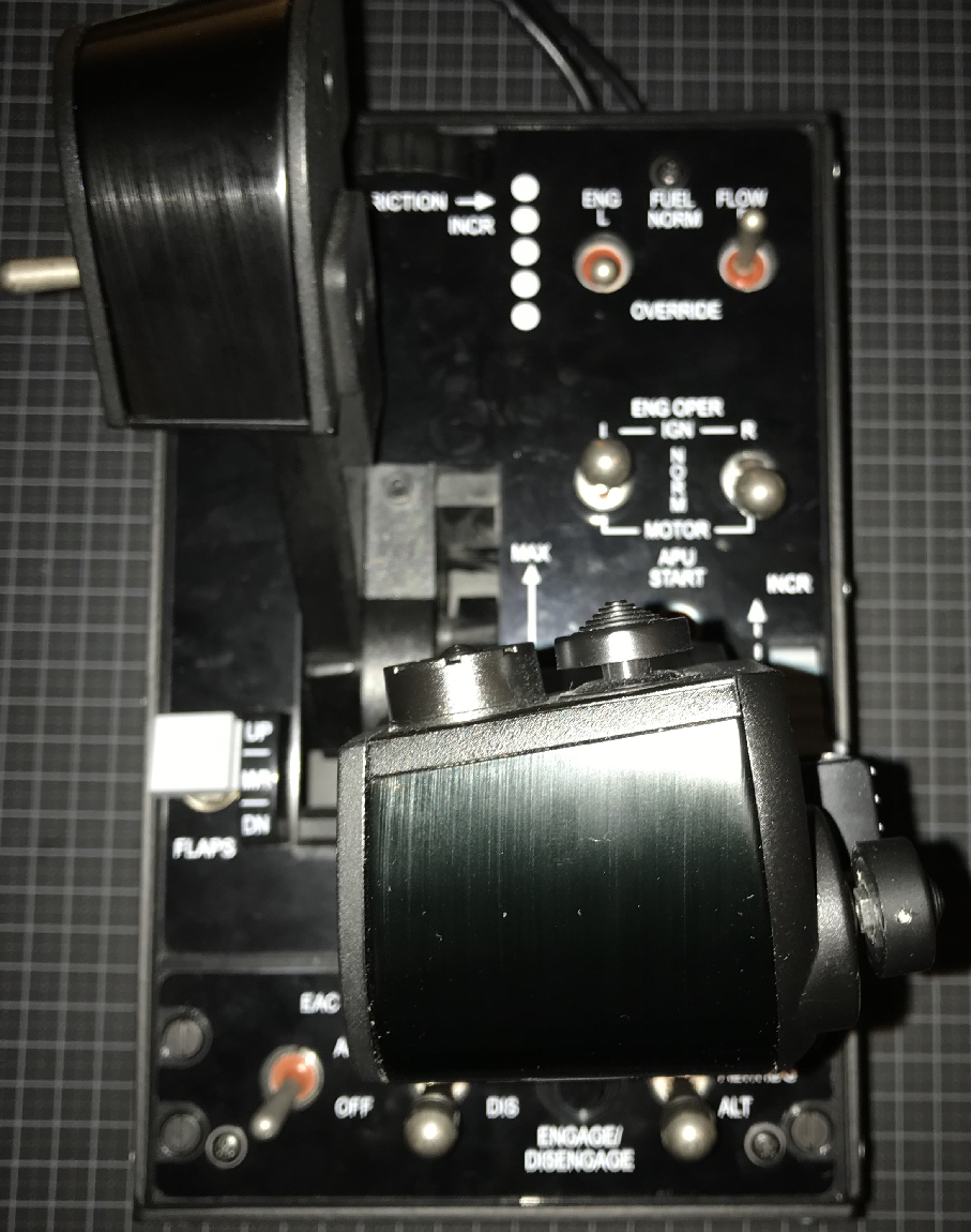
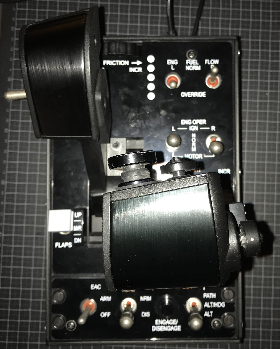
Cheers guys So here's a fun little thing I put together I don't have room for a full pit in which to integrate a "full" landing gear handle setup, so I have been struggling to find a satisfying solution beyond toggle switches with 3d printed levers stuck on them. What I did was I bought a Tornado gear switch assembly on EBay (as others around here have) and converted it for use with DCS and mounted it to the side of a Monstertech joystick table mount. It is fun to operate and makes landings and takeoffs that much more involved when you have to throw that heavy handle :joystick: The box fits pretty snugly on the side of the alu profile and doesn't get in the way of joystick or leg/rudder movements in neither up or down handle positions. I have it sitting high enough off of the mounting plate so it is easy to grab and operate without getting any fingers pinched. To be more realistic it should probably sit off to the left side of the throttle of course but I found it interfered with the throttle when I tried mounting it there. In practice I find it very easy and fast to find and operate the gear lever without having to look down. To hold the box in place I tried plastic strips and clamps at first which didn't really work. I then tried clamping it using standard corner brackets from Monstertech and it turns out that they fit just perfectly! They're cheap and easy to install. I'm thinking to buy another gear switch and convert it to a hook handle that I can place on the right side of the joystick for added fun around the carrier. The switch assembly has the wiring schematic printed on the side and the pins on the back are labeled so wiring it up was very straightforward. I didn't have a mil connector and I didn't want to pry the thing open so I soldered directly onto the pins in the back. A crappy but functional solution. I have it hooked up to a Nano running DCS BIOS and it works perfectly with both the F/A-18C and the A-10C. I'm sure it would work with the other modules but I haven't tested it. There were little bulbs in the gear handle but I couldn't get them to light up so I swapped them out for a pair of ultra bright red LEDs. I drive them with 5V PWM straight from the Nano with no issue. They look white in the video but they actually shine a nice red. The assembly has a mechanical downlock that is disabled by either manually pressing the override button or by activating the solenoid inside. It is rated at 28V but 12V from a regular (switching) wall adapter works just fine. I control power supply for the solenoid with a little MOSFET circuit that engages when DCS BIOS outputs an airspeed higher than taxi speed, since we can't seem to check for weight-on-wheels directly. More precisely I read the airspeed gauge postion and just engage the 12v when it is above 10% of max or whatever. Here's crappy video showing the switch in action. You can hear a clank as the jet accelerates and the solenoid energizes and disables the downlock. Here's link to the Monstertech corner brackets - needs the fastening set option to attach to the profile.
-
Haha that's so cool! Looking forward to see more of your design That's a really neat way to attach the box to the throttle. Amazing the design flexibility you get with a 3d printer.
-
DCS-BIOS F/A-18C library. Get it here!
DeadMeat replied to Bullant's topic in Controller Questions and Bugs
Hi John, I fear that I may have complicated matters by suggesting you guys edit the module since we're now no longer working on the same file. If AndrewW updates his original upload it would make sense to revert to that to make troubleshooting easier. Anyways, I've just tried the FCS reset and the T/O trim and they worked fine for me with no edits, so I'm not sure what's wrong on your end here. I then tried the comm panel and it didn't work at first but after updating the device IDs to 40, they worked fine. Tested the IFF and ILS toggles and the RWR volume pot with no issue. I can think of a few things that could have gone wrong for you You may have broken something in the module during your edits - re download and edit one thing at a time and verify it works You may be copying commands with wrong addresses if the documentation is not updated after edits (try to delete the JSON files and then start a mission and refresh the command reference) There's an issue with your switches or wiring - confirm they work with other functions you know work in the sim -
DCS-BIOS F/A-18C library. Get it here!
DeadMeat replied to Bullant's topic in Controller Questions and Bugs
I don't think there's a specific output for backlight in any module. What you could do is something like this, where you basically read the position of the consoles dimmer knob/pot and output that as a PWM signal controlling the intensity of LEDs directly (be careful not to fry the board by exceeding the amp ratings) or via a mosfet setup. For extra credit you could add some checks to infer if conditions allow the backlight to function when turning the knob, e.g. power on the AC bus.. void onConsolesDimmerChange(unsigned int newValue) { analogWrite(PIN, map(newValue, 0, 65535, 0, 255)); } DcsBios::IntegerBuffer consolesDimmerBuffer([color="Red"]0x5552c, 0xffff,[/color] 0, onConsolesDimmerChange);Be sure to check your own documentation for the correct function address in red. I don't check for initial state I just reset the switches before starting according to the mission scenario (air start, cold start..) While I don't think there's a native or simple way to scan for switch state at startup I suppose you could scan for the module name change (indicating a mission start) and then do the senddcsbiosmessage dance for the whole lot. Ian commented on the topic here a while ago.. -
DCS-BIOS F/A-18C library. Get it here!
DeadMeat replied to Bullant's topic in Controller Questions and Bugs
No prob. Note that when you change stuff like this in your dcs bios module it may rebuild the addresses for other stuff. Most likely your LEDs will be affected, but also switches if you're outputting their position. Simply check your arduino code against the new documentation and it should be obvious if you need to change something and re-upload to the board. For example I had the APU ready light coded at DcsBios::LED apuReadyLt(0x54b4, 0x0100, PIN); but it changed to DcsBios::LED apuReadyLt(0x54b2, 0x8000, PIN); after I messed with what I described in the previous post. I don't know if it is possible to retain addresses between updates to the module, so I think we have to live with having to fix code during the development of the Hornet, as functions are added and changed. Oh well :music_whistling: -
DCS-BIOS F/A-18C library. Get it here!
DeadMeat replied to Bullant's topic in Controller Questions and Bugs
As Capt Zeen pointed out elsewhere, one of the latest DCS updates changed the device ids for some functions. This includes the Radar and INS switches. Until AndrewW updates the library, here's a quick fix for those two switches. Edit your FA-18C_hornet.lua (..\Saved Games\DCS\Scripts\DCS-BIOS\lib): Change defineTumb("RADAR_SW", 43, 3001, 440, 0.1, {0.0, 0.3}, nil, false, "Sensor Panel", "RADAR Switch (MW to pull), OFF/STBY/OPR/EMERG(PULL)") defineTumb("INS_SW", 45, 3001, 443, 0.1, {0.0, 0.7}, nil, false, "Sensor Panel", "INS Switch, OFF/CV/GND/NAV/IFA/GYRO/GB/TEST") to defineTumb("RADAR_SW", 42, 3001, 440, 0.1, {0.0, 0.3}, nil, false, "Sensor Panel", "RADAR Switch (MW to pull), OFF/STBY/OPR/EMERG(PULL)") defineTumb("INS_SW", 44, 3001, 443, 0.1, {0.0, 0.7}, nil, false, "Sensor Panel", "INS Switch, OFF/CV/GND/NAV/IFA/GYRO/GB/TEST") Tested and works as a multi position switch again. Haven't tried with an encoder though. Other functions have broken in a similar way, e.g. the KY58 panel. Compare your FA-18C_hornet.lua module with devices.lua (..\DCS World\Mods\aircraft\FA-18C\Cockpit\Scripts). Quick fix, edit your FA-18C_hornet.lua and add it yourself: Change --create_caution_lamp(CautionLights.CPT_LTS_LDG_GEAR_HANDLE) to defineIndicatorLight("GEAR_LEVER_LIGHT", 227, "Landing Gear Handle and Warning Tone Silence", "Gear Lever Light") Start a flight with the hornet to update your documentation files and the function will show up in the dcs bios documentation (refresh the page) in the landing gear handle and warning tone silence category. Tested and works with an LED. -
Very cool! I'm always amazed at the creativity around here. Looking at your first couple of pictures though, this is what I immediately thought of :D My friend had one many years ago and man it was just the greatest thing ever :joystick:
-
Lost Wartohog/Cougar Pickle Button
DeadMeat replied to xWARGOx's topic in PC Hardware and Related Software
For a good time try THIS It'll put 4 lbs of click in your .. pickles -
DCS-BIOS F/A-18C library. Get it here!
DeadMeat replied to Bullant's topic in Controller Questions and Bugs
Thanks again for putting in the work on this stuff. It really rounds out the module with all of the gauges and outputs. I tested the IFEI outputs and overall they worked really well. Just a few issues came up that you may want to look into: Seems a couple of texture visibility outputs are missing: Z (zone), L and R for top/bottom fuel. NOZ too, but I think that always follows the scale texture, so it's not really necessary.. You have the texture visibility output for the pointers, but not their actual angles/positions (not sure if it is possible to extract that) Missing output for top fuel row during time set mode (for +/- hour offset for zone) Missing ET/timer outputs (bottom time display) -
The Hook Bypass switch starts in FIELD mode by default when doing a cold start from an airfield. It should start in CARRIER, as power from the generators/ground power is off. Further, if it is not manually cycled to CARRIER and back to FIELD after power-up, the switch stays in FIELD does not behave as it should i.e. it doesn't revert to CARRIER when turning the power off again or when lowering the hook in the air after takeoff. This second issue also arises when starting in the air or with engines running on the ground. In these cases, the switch also starts in FIELD position (which otherwise seems fine, since it could have been put there after engine startup) and won't spring to CARRIER when cutting generator power or lowering the hook. The only cases I could find where the switch starts as intended/works as it should without cycling it first, is in a cold start on a carrier (via mission editor) and in the carrier takeoff instant actions. 2.6.1.6 Approach Lights/Arresting Hook Floodlight. 2.12.10 Angle-Of-Attack (AOA) Indexer.
-
NP. Just tested again. Seems I did had the old archive :huh: Most switches work, but these are still broken. I think you are aware of them already though: Great :thumbup: keep it up!
-
Good work Andrew, quite a lot of what you have done works fine, but it seems the hornet doesn't play 100% nice with dcs bios right now. Looking at the F18 cliackable_defs.lua they've defined a lot of new switch types and they have more parameters for animations etc. compared to the A10, so that may be throwing dcs bios off. It looks pretty messy in there right now but I'm no expert and the thing is in alpha so ok.. So I've done some limited testing of your F18 module with a prototype panel that I've confirmed works with the A-10C on the same DCS install. Just testing simple switch functionality. That still leaves LED outputs, >3 position switches, potentiometers, gauge/servo output and mag switches etc to be tested if anyone is up for it.... 2 position switches (position 0/down/out or OFF ususally, pos 1/up/in or ON usually) 3 position switches (position 0/down, pos 1/middle, pos 2/up) So some switches are not behaving.. Maybe DCS BIOS needs to be tweaked to handle the new switch definitions? Perhaps some of the guys with more insight into 'the lua' can figure it out :)
-
That was quick :) Your zip seems to be missing the json files for the f18 for it to show up in the control reference - or another updated file is missing for those to be generated automatically. Tried it on a fresh dcs bios download
-
Interesting.. Have you considered that these switches appear to be implemented as solenoid held in the EXTEND and FIELD positions respectively? They should only stay latched if parameters are right (WoW, battery power, hydraulic pressure and what have you..) For the A-10C solenoid held switches I believe Ian stated that DCS BIOS would actually flip the switch and it would just return very fast to off if parameters were not right for it to stay latched in the on position. The A-10C ANTI SKID skid switch would be an example of this - but then ED may have coded controls differently this time around. Of course we are talking alpha state hornet here so switches could still be buggy..
-
Warthog AP engage/Disengage
DeadMeat replied to Markeebo's topic in PC Hardware and Related Software
The button is held in place by two tabs, one on either side of the button behind the panel. Simply press these in and pop the button out through the front. Cut the wires close to the button so you have something to play with when you solder on a replacement. I think you may have to remove the decorative panel from the front first, though. It is simply held in place by screws in front and some double sided tape, but then you must already have removed it if you get the toggles out? The button itself is a proprietary Thrustmaster design so I suppose you'd have to get a replacement directly from them if you want a one-to-one drop in replacement. You should contact them before you snip any wires if you want to go that route. The button on the real LASTE panel is a MS25089-3G https://forums.eagle.ru/showthread.php?t=160350 e.g. OTTO P1-72622 https://www.mouser.com/datasheet/2/603/Otto_P1_Sealed_Military_Pushbuttons-1214958.pdf Any other push button with normally open circuit that fits should work though. I switched mine out with OTTO P1-71122 on the throttle panel. It works fine our purpose and it has the heavy 4 lbs actuation force. The feel of the OTTO button is just incredible compared to the stock TM. To fit the button, I had to enlarge the hole in the front panel a bit. Also, I removed the TM 3 toggle PCB completely to make room for mil-spec toggle switches, so I'm not sure the OTTO switch will fit if you reinstall the TM PCB. -
So happy to hear that it is working out for you guys. Nice! Keep at it. A PS style thumbstick should be much better than the stock TM sensor even if it is "tier 2" compared to a force sensor. The lower price point would also put it in the range of a lot more of the warthog user community. Nice one :) Be careful about modding the warthog. You start with just one little button, then its a professional grade slew sensor and then it just takes off and you end up swapping everything out for mil spec switching hardware, mag switches and it just goes on and on :lol:
-
Wow congrats on completing such a nice kit :thumbup: This is surely a must have mod for anyone with a Warthog throttle (and change to spare) I mean the ergonomics of slewing is just night and day with a proper sensor like this compared to the stock TM. It really makes the flying experience much more enjoyable as you can spend your time fighting the actual targets instead of fighting the crappy TM slew control :joystick:
-
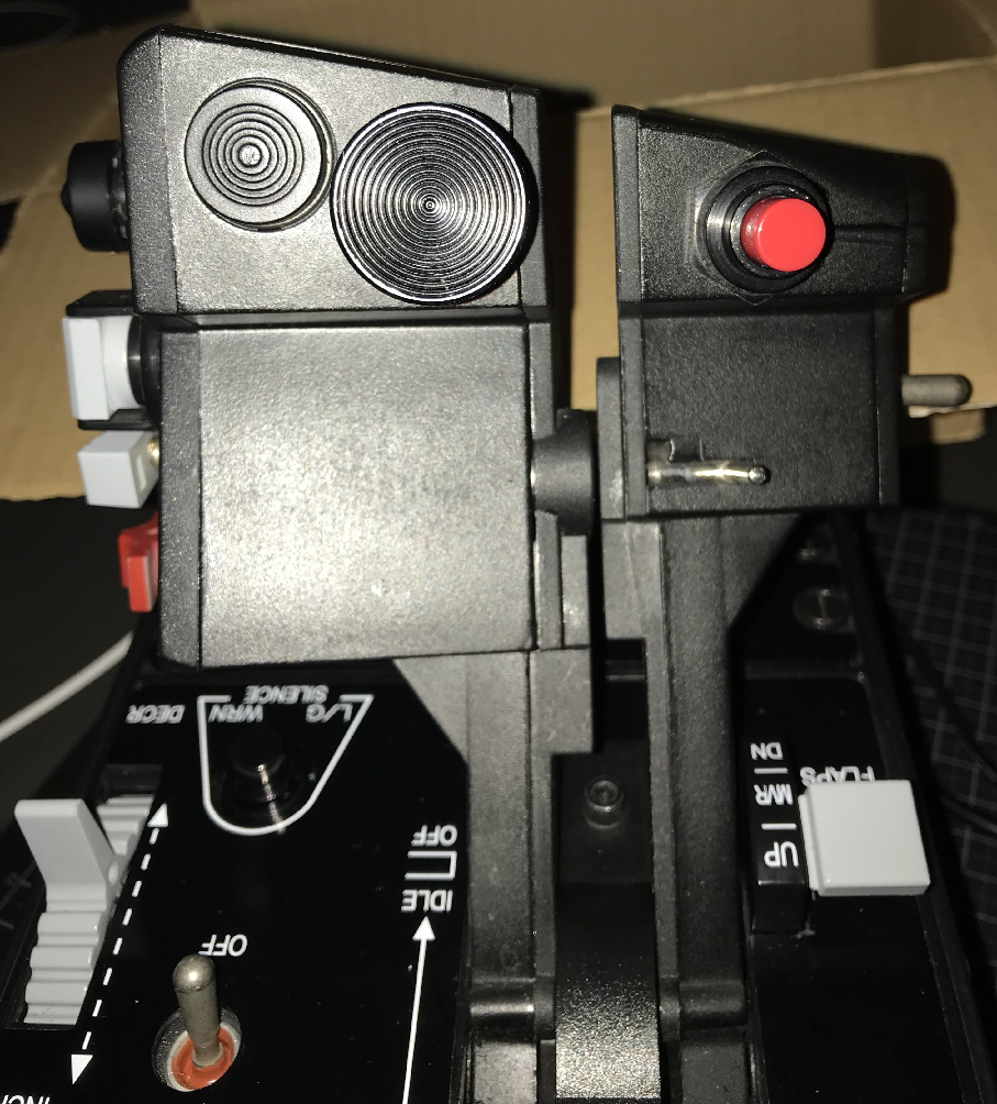
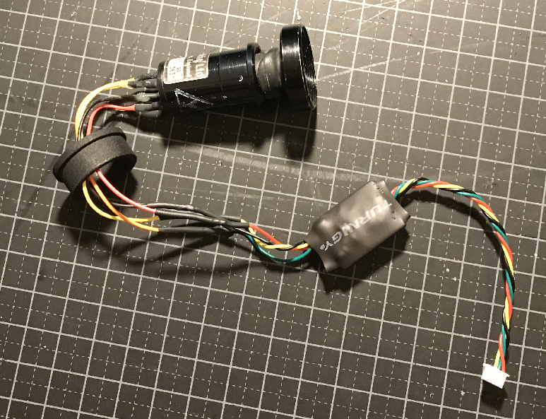
So I've been playing around with the calibration of the DACO on my throttle (I bought that other Chinook stick on EBay and OP hooked me up with a very nice plug-and-play i2c adapter board and 3d printed fitting ring.) I can safely say that it is way better than the stock TM sensor and it makes it easy and quite enjoyable to slew the sensors around as it should be. As you point out there are a couple of issues though, - Availability/affordability is at the top since there's simply not a lot of *cheap* DACO or OTTO transducers out there. The 462+a custom integration kit sounds like a reasonable choice IMO even if it will still be too expensive for some.. - No center push button. I never used the functionality on the TM sensor and I don't miss it but I guess some folks do. Oh well.. - Sensitivity could be a bit better on the DACO I suppose, so it sounds like the 462 is a good choice if it performs even better. I don't know how sensitive the real A-10C sensor slews in practice, so I'm not really sure what to measure up against though. - Size and position of the DACO hat means it can get in the way when you're working the coolie hat rapidly switching SOI and MFCD pages during an engagement. Below you can see how the hat sticks out compared to the stock TM and how it could get in the way when reaching for the coolie hat: You sort of have to be a bit more deliberate to reach and push the coolie hat to the right but with some practice I find that it works fine and doesn't really slow down the frantic SOI togglin'.. The DACO hat doesn't move more than a mm or two so that helps in not getting in the way and not creeping noticeably when working the throttle or resting a finger on it. The 462+a smaller, tighter mounted hat closer to what the stock dummy TM hat looks like should solve the issue I think. It does look really good! The tighter integration and smaller hat will make it easier to work the throttle and coolie hat compared to the DACO. If you can't get the hat in nice grey color I personally would probably go for black over red.. For the DIY folks you could consider making the hat available in Shapeways' frosted ultra detail material. This would make it easy for them to simply paint the hat grey or whatever. The material works really well for Deadman's knobs. It doesn't require much/any sanding and can easily be tapped and hold a set screw for mounting. Looking forward to see your next evolution on the design!