sharkfin61
-
Posts
422 -
Joined
-
Last visited
Content Type
Profiles
Forums
Events
Everything posted by sharkfin61
-
Jetzt habe ich so unbgefähr alles was den Defender betrifft de-aktiviert. Ergebnis bleibt gleich :(

-
Versuche ich, vielen Dank!
-
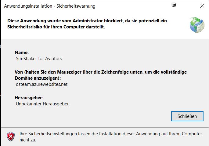
Ich habe gerade versucht, nach der Defender Deaktivierung die SSA_Setup.exe zu starten. Allerdings ohne Erfolg. Bei jedem Versuch erscheint sofort die Warnung wieder. Gibt es noch einen aktuellen Lösungsansatz?
-

[Official] SimShaker for Aviators
sharkfin61 replied to f4l0's topic in PC Hardware and Related Software
It's made out of leather-look black vinyl, "artificial leather" :) -
[Official] SimShaker for Aviators
sharkfin61 replied to f4l0's topic in PC Hardware and Related Software
Hi Andre, as I couldn't find any answer via the search function, just a short question on dimensions. I have a "Playseat Evolution" setup. Will the GAMETRIX JETSEAT KW-908 fit into the chair (in other words, be soft enough to match with the shape)? Or will the "VIBRATING PAD GAMETRIX JETSEAT FSE" be more suitable as my "Playseat Evolution" is already narrow. -
Very detailed and in a very professional manner! I wish there where more instructional videos on such aspects, like that one! Felt like I was back in my "Falcon" days, where someone gave online lessons about fighter/ formation geometry. :thumbup:
-
Thanks a lot for your reply, will try immediately.
-
Maybe someone can check in which direction the connector plug sits on their PCB? Please! AGM 65 update and I can't fly the whole day long ;-)
-
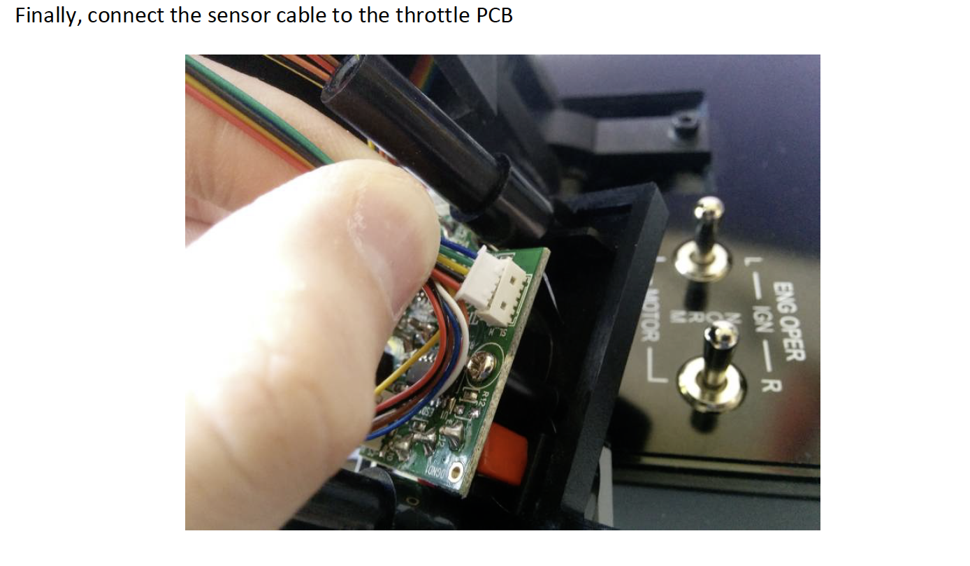
Alert!! After receiving my parts, I finally had the time to open the housing of my throttle and disassemble it. After putting the sensor into place, I was about to connect the pin to the PCB. Following the downloadable instructions (very precice, btw), I found, the connector of the sensor doesn't plug in easy to the counterpart on the PCB. The photo in the instructions shows the red cable in the outermost left position However, the red cable of the new sensor is on the other side of the of the pin. I know that the connector has a specific shape to prevent plugging in the cable the wrong way, but regarding the picture in the instructions, my direction is wrong (at least if I refer to the colour of the cables) So ... am I right to connect the pin to the PCB with the red cable on the right side? (like shown on the first picture) Pic's attached (first mine, second frm. instructions)
-
Got mine (order# 1268 ) today, thank you! Took a day off tomorrow. :excited:
-
Nice skin (just keep in mind the Hueys were transferred to the German Army :cry_2: )
-
Thanks a lot to both of you, WILCO!
-
Need some advice. I just received a pair of used CH Pro rudder pedals. I know, they run on wheels inside the housing but, is there a benefit in cleaning and re-greasing the portion of the housing, where the wheels run on?
-
try that: https://forums.eagle.ru/showpost.php?p=3555530&postcount=118
-
Virtual Cockpit Server for DCS World
sharkfin61 replied to gear_monkey's topic in PC Hardware and Related Software
What I did was to alter the "A-10C Virtual Cockpit Server.lua" in side the Savedgames\DCS.openbeta\Config\MonitorSetup folder like this: Works like a charm. Also altered the *lua files like I described in CaptZeens Helios thread https://forums.eagle.ru/showpost.php?p=3556766&postcount=128 -
Capt Zeen F/A-18C Beta Helios Profile ! ! !
sharkfin61 replied to Capt Zeen's topic in PC Hardware and Related Software
Just tested, even with todays update (2.5.2.19273.411), you still have to alter the numbers as suggested by Right Stuff to have a crispy picture exported.:noexpression: I tried these for now: stroke_thickness = 0.2 stroke_fuzziness = 0.3 -- Currently is used for DMC generated fonts black outline DMC_outline_thickness = stroke_thickness * 3 DMC_outline_fuzziness = stroke_fuzziness * 1.1 DMC_stroke_thickness = 0.2 DMC_stroke_fuzziness = 0.3 (Flying with a 43inch 4k TV setup, maybe hud lines get too thin/faded on lower resolutions) -
Right Stuffs solution for that: https://forums.eagle.ru/showpost.php?p=3555460&postcount=117 and the follow up posting for the AMPCD https://forums.eagle.ru/showpost.php?p=3555530&postcount=118
-
Capt Zeen F/A-18C Beta Helios Profile ! ! !
sharkfin61 replied to Capt Zeen's topic in PC Hardware and Related Software
Rep inbound !! -
Capt Zeen F/A-18C Beta Helios Profile ! ! !
sharkfin61 replied to Capt Zeen's topic in PC Hardware and Related Software
Have mine on a 1280x1024 screen, they are blurry also. Or did you mean the overall resolution of DCS? -
Thanks a lot! You just made my summer holiday very busy ;-)
-
Thank you for the offer, maybe I will check back later (after a few updates where made).
-
In the latest episode of Wags videos (Ep. 14 CCIP auto mode) he turns off the map on the AMPCD again. So let's hope this video is an actual one and we get that feature back soon, maybe with the next update.
-
Is there any official training syllabus for the F-18 C transition available? I'm trying to learn things one after the other this time, maybe that will help me .:smilewink:
-
Depends on country, airfield and (probably) aircraft. German Air Force wants to call you for start-up.
-
Anyway it would be nice, if the throttle would be enabled again when shutting down TARGET or stop running the profile.