sharkfin61
-
Posts
421 -
Joined
-
Last visited
Content Type
Profiles
Forums
Events
Everything posted by sharkfin61
-
So, looks like I received my MTO (milling tasking order) for this afternoon Thank you.
-
Well here are my efforts so far: Yesterday, upper left is the knife you mentioned, the white spot below was the 3,18mm (yes, I forgot to change the bit after cutting the "backwards" letters where done with teh dremel bit (better as <i expected) The white spot in the middle was the 2mm blue-coated endmill. Some more The circles were all engraved at 0,05mm depth, in different forward speeds (left slowest, right fastest, 1500 mm/min iirc) The best result, from my point of view, is in the middle (scaled the letters to 150%) Plexi was coated with 1 layer of paint, dryed overnight in my ice cold garage. Nevertheless, I just ordered the 445nm lasermodule. Hoping for thursday to arrive.

-
As for the data while cutting the panels/ clearing the pockets: 8000 rpm FwdSpeed was under 200 mm/min (78 inch/min) Depth of each cut was 0,5 mm (1/5th inch) tip thickness : 3,175 mm (1/8th inch) single flute upward endmill bit Software was "Estlcam" When I tried engraving the letters afterwards, I used different bits. A 30° engraving bit that came with the saintsmart genmitsu 3018pro, a dremel V-nut with 8 flutes or so, and a blue-coated endmill 2mm. I'll upload a picture of the outcome.
-
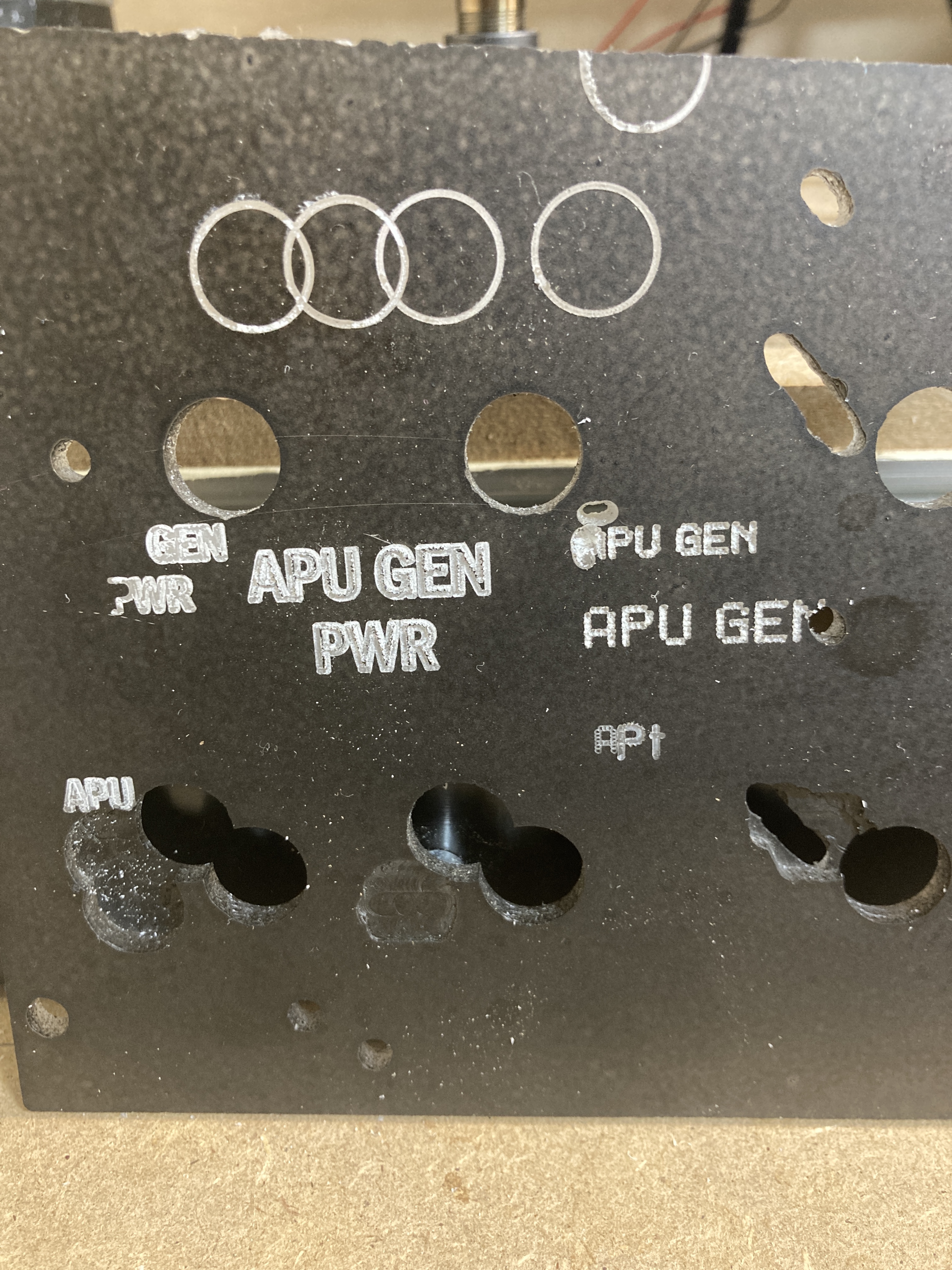
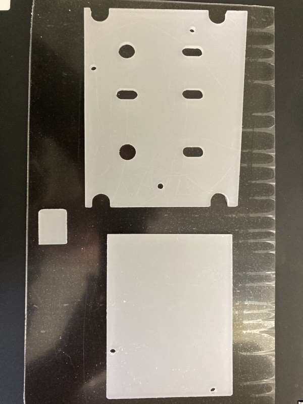
Well I'll have a look into that option. Do you have to turn it around after milling the first side? Meanwhile, I think not so bad for the first attempt: At the moment I am trying to figure out how I can engrave the letters into a black-coated acrylic board without clearing the insides of, let's say, an "A" or a "R" or an "O".
-
Thank you, No1sonuk for your encouraging words, that was exactly what I needed yesterday, before I went to sleep. I was just about to throw al my plans and tools into the bin. After frying my controller board of the 3018 with a stronger spindle and breaking two bits while fiddeling around with setting on the mill, I was close to a nervous breakdown. Well, I guess I'd been playing around with fusion360, grbl, candle, ugs a.s.o. for too long that day and having such a fiasco gave me the rest. Nevertheless, today is a new bright day; I'll start all over again and write it on a big piece of paper: "Rome wasn't built in a day", followed by "Haste makes waste".! Wanting too much too fast, isn't a good idea and I have to realize that I'm still in my baby shoes as a carpenter, locksmith, coder, painter, electrician and ..... When you mill acrylic, you mean cast acrylic, I suppose? Nice addition is that bit fan. I'm still searching for a location to buy it on the old continent (last time I bought some Leo Bodnar boards or ordered something at pcflights.com, I almost fell off my chair when paying customs and import tax for the parts and shipping). Well, life will go on and today I will try again to mill the baseplate for my electrics panel. Pics when it't done
-

HOTAS recommendations
sharkfin61 replied to Heliflyer_71's topic in PC Hardware and Related Software
I would definitely go for a joystick system in conjunction with rudder pedals, rather than a twist grip option. on my second rig (mainly for testing and programming), I have a X52pro connected. OK for fixed wing, almost undoable with rotors. Just for consideration. -
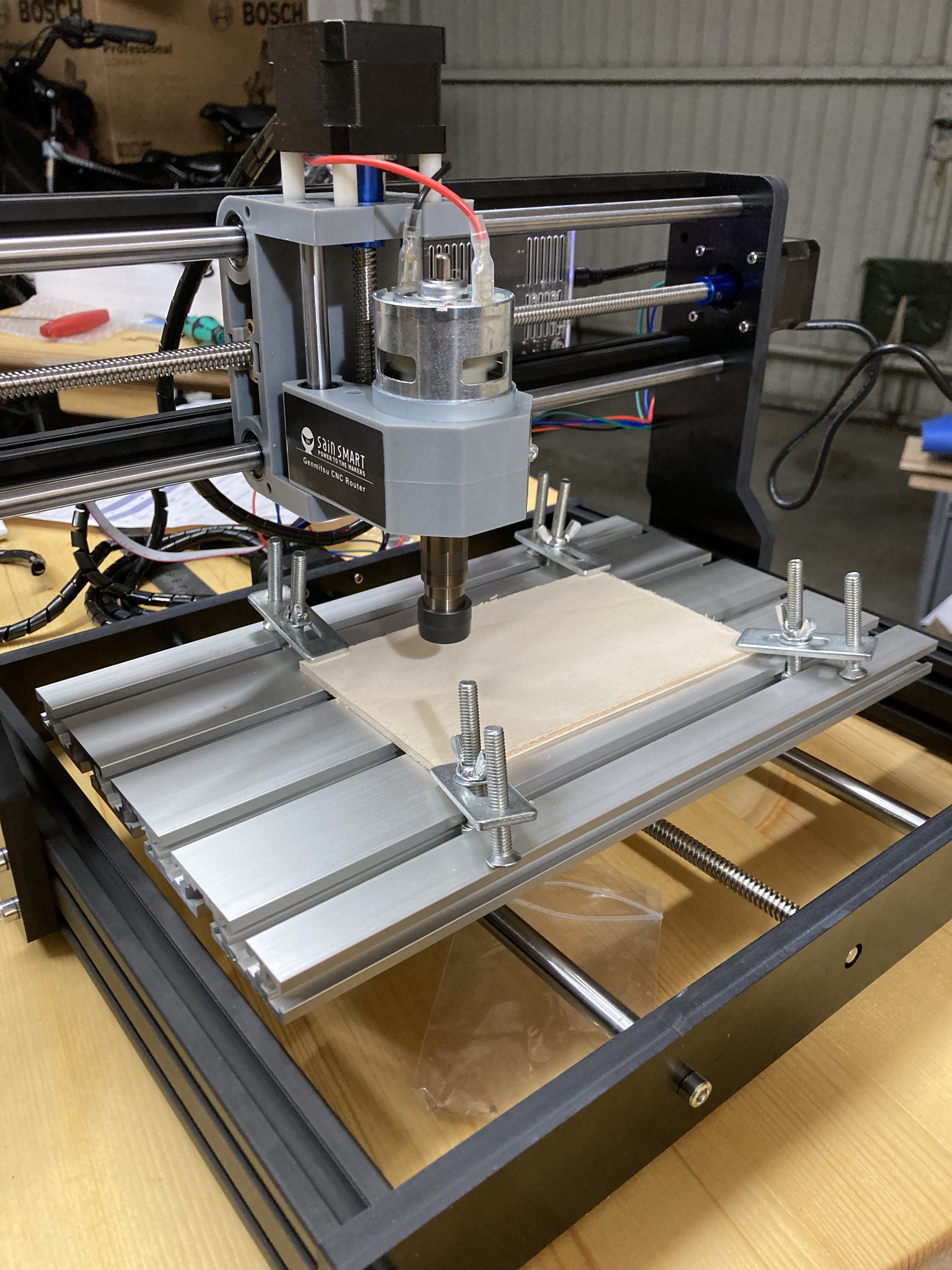
Latest toy: To be honest, I'm a little bit scared of the new learning curve for a CAD program. But having so much trouble to find a working screen for pre-fabricatred panels and the constant need to alter something to make another part fit pushed me to that decision. I plan to upgrade it with a 15 W Laser Module, soon. But maybe the CNC engraving of the acrylic is enough for nice panels. May the new madness begin.
-
Thank you for the input. As long as you are designing and milling/lasercutting your own ARC-210 panel (and not using the pre-fabricated one from pcflights.com, as I had to do) a 3.5" display will be a fine solution, as you can use it as a shield for the Arduino and every pin will fit into a correspondent right I/O socket on the board. My first approach was this display: 3.2" SPI display (fits perfectly, but runs on 3.3V and didn't work at all, no specific documentation included, also) LCDwiki.com gave me a little bit of hints, but I still can't convince the d..n thing to run. Next was a 3.5 display, formerly advertised as a 3.2" : TFT module for Arduino Mega/Uno The one I'm waiting now for is another shield-like: 3.2" shield for MEGA2560/ UNO I hope this time it will be really a 3.2". On the other hand, as long as the ARC-210 isn't implemented in the simulation, there is no need to hurry. Although a new fiscal year has already begun, I'm still struggling to explain my expenses for the last projects, products and tools. So, to not annoy the Secretary of Treasury, I have to lower my pace a bit...
-
While I'm still waiting for a 3.2" lcd display for my ARC-210 that is working with my MEGA2560s or my UNOs (last two items I ordered where either wrongly advertised and therefor too big or didn't run on Arduinos), I used the time today to progress with my AHCP. I will glue on the printed transparent foil on it. So curious to find out, if the print is black enough when it is finally sticking on the panel. My need for a Laser engraver/ milling machine is getting stronger and stronger....Cutting the acrylic sheets with a chopsaw worked but cutting 5mm plastic with the electric jigsaw isn't really fun. Things to do: - drilling the holes for the LEDs and solder them in - soldering the wires to the switches - encasing the panel to rise it at least 22mm (TFT behind the main console) - connecting to the BBI-32 (overdue for 5 days, thx to BREXIT)
-
Did you have any further success with the ESP32? I was thinking about the same kind of board to speed up the graphics on my ILI9341 TFT for the A-10C II radio display. Glad I read your posting first.
-
Question: best way for connecting stand-offs
sharkfin61 replied to sharkfin61's topic in Home Cockpits
The stand-off I used, was a brass stand-off. I think it cut it's own thread into the acrylic. I used the nylon stand-offs in my CDU project, I know about their weakness when it comes to threads. But thank you for the headsup. Oh, yes, the other problem was, I didn't have a taper for the M3 screw. Only m5, m6, that I bought for the woodwork. Gesendet von meinem SM-T820 mit Tapatalk -
Question: best way for connecting stand-offs
sharkfin61 replied to sharkfin61's topic in Home Cockpits
Thanks for the answer. I made a first drill hole in 2,5mm Plexi (Acrylic). I screwed in the stand-off without taping a thread (M3 stand-off into a 2,4mm hole). Fitted tightly and sturdy. I didn't think it was so easy. Well, the learning curve in pitbuilding is still as steep as the A-10C II type related training. -
Watching RomeoKilo's video about his ARC-210 panel implementation yesterday, I wondered how the mainboard stand-offs where put in place and fixed to the panel layer. Is it necessary to drill a hole and tap a thread into it or will glueing (CA or Epoxy) them into the hole be enough when you screw the pcb's or next layers onto it? As I have to work with pre-fabricated panels from pcflights . com , I only have one try. Thanks for your inputs.
-
Great video about your ARC-210! Thank you for all the inspiration and explanation! https://www.youtube.com/watch?v=aRrlgF6j6ro&t=1s
-
Well, industrial approach to simulation. But a good blueprint for those with lot's of money, time, passion and patience.# Thank you for the link.
-
Helios 1.6 - Official Thread
sharkfin61 replied to derammo's topic in PC Hardware and Related Software
Good to hear! Now, have a lot of fun with DCS. -
Have you tried :
UIMainView = Viewports.Center -
Can you post your actual helios.lua? (to avoid spamming the thread with code)
-

_ = function(p) return p end
name = _('Helios')
description = 'Generated from compatible Helios Profiles'
F_16C_EHSI = { x = 1968, y = 2049, width = 188, height = 184 }
F_16C_LEFT_MFCD = { x = 0, y = 1440, width = 550, height = 550 }
F_16C_RIGHT_MFCD = { x = 1968, y = 1440, width = 548, height = 549 }
Viewports = {
Center = {
x = 0,
y = 0,
width = 2560,
height = 2240,
aspect = 1.14285714285714,
dx = 0,
dy = 0
}
}
UI = { x = 0, y = 0, width = 2560, height = 1440 }
UIMainView = UI
GU_MAIN_VIEWPORT = Viewports.Center
-
-
Helios 1.6 - Official Thread
sharkfin61 replied to derammo's topic in PC Hardware and Related Software
I guess if you set the red height to something else than 2240 and don't the aspect ratio it won't fit (should be 1,777777777777778 in that case) ALso you have an extra line in your helios.lua: UI = { x = 0, y = 0, width = 2560, height = 1440 } Here's my .lua to compare (I extracted the viewport for th A-10C CDU, positioned in nvidia setup right of my main screen): _ = function(p) return p end name = _('Helios') description = 'Generated from compatible Helios Profiles' A_10C_CDU_SCREEN = { x = 1945, y = 0, width = 773, height = 595 } Viewports = { Center = { x = 0, y = 0, width = 1920, height = 1080, aspect = 1.77777777777778, dx = 0, dy = 0 } } UIMainView = Viewports.Center GU_MAIN_VIEWPORT = Viewports.Center -
Helios 1.6 - Official Thread
sharkfin61 replied to derammo's topic in PC Hardware and Related Software
Maybe the missing bezels are part of the background. For the gauges, I did the similar thing (copy out of a working profile) with the A-10C profile to fit it into my main console. Worked almost out of the box. What I missed was to press the shift key when trying to resize them. -
Does Helios really show your lilliputs underneath the main screen? Perhaps you have to set up their position inside Windows right of the mainscreen, side by side (regardless of their "physical" position in front of you). Resolution should be 3760x1440 now. Then use the „reset monitors“ function inside helios. Also check if you already added the "Profile->Add Interface->DCS Aditional Viewports INstall the patches, go to the HELIOS "Interface Status" tab and see if there are any warning signs. In your HELIOS "DCS Monitor Setup" tab, scroll down to the end and click "Save Profile". In the "DCS Monitor Setup File Output" portion of "DCS Monitor Setup" tab, click the configurre" button. Then, (at least I had to) choose „helios“ under the in-game monitor settings.
-
Thank you, No1sonuk, I will configure them as digital in/outputs. Glad I asked before I started building, I learn with every failure
-
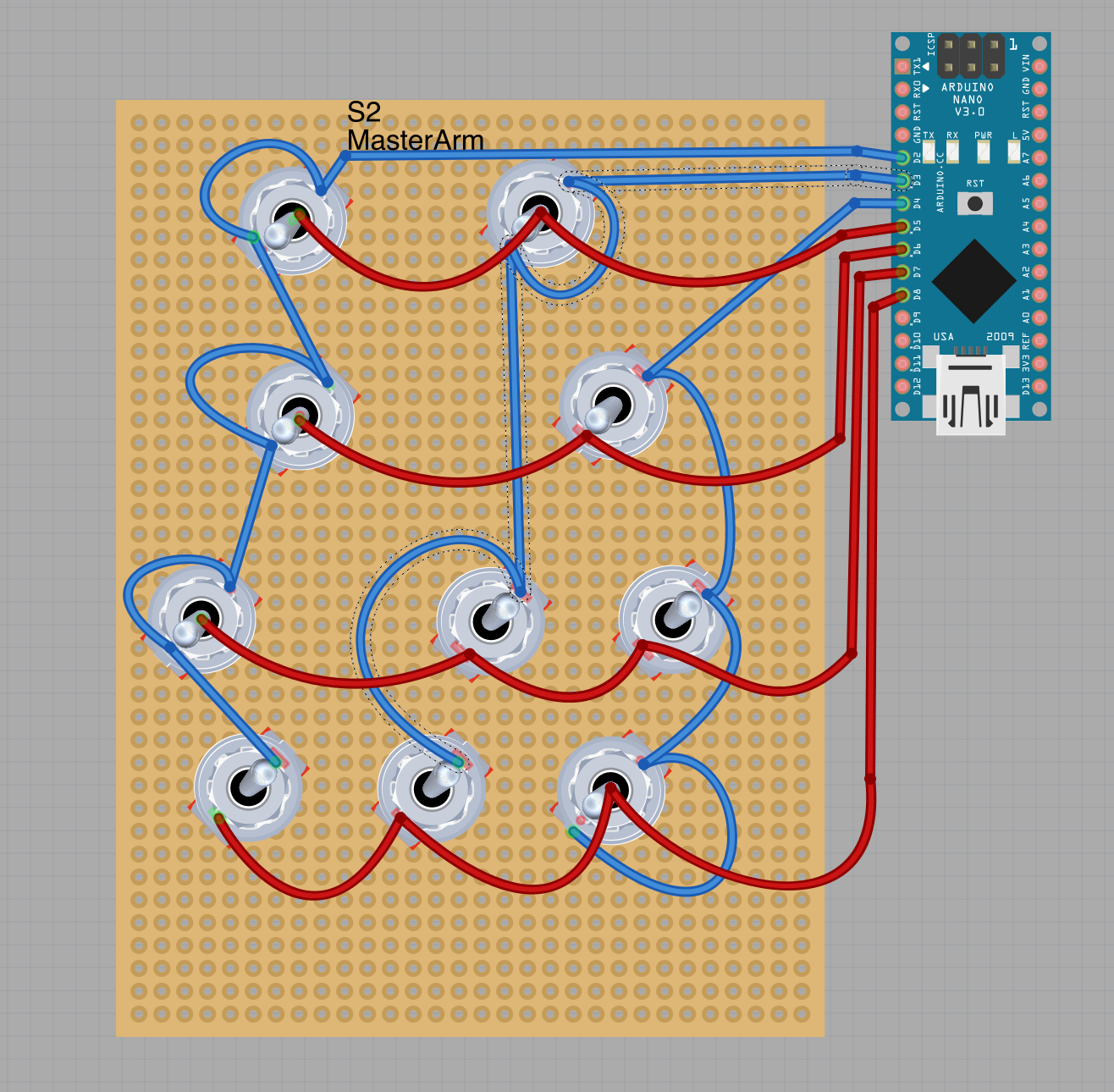
Thanks a lot to both of you, I will reconsider my decision with the matrix and go for the dedicated inputs. (Special kudos for the drawing, @crash test pilot!)
-
Maybe someone with some knowledge about matrix arrays can provide me with advice if I planned the AHCP wiring correct. I have my doubts if the connection of the On-Off-On switches (both connections in serial) can be done like in my plan.
-
@jj3 , any updates on your CDU?