JBDCS
-
Posts
25 -
Joined
-
Last visited
Content Type
Profiles
Forums
Events
Everything posted by JBDCS
-
investigating Cannot calibrate Gyro with Mag Compass
JBDCS replied to Nealius's topic in Bugs and Problems
I've just checked in the setup files for the P-47 and the Spitfire. Those two both have pitch and bank correcting compasses in game - they have a max_pitch_bank setting in the setup file and details of the compass gauge pitch/bank/heading cockpit argument numbers towards the end of the file. For the P-47 the max_pitch_bank limit is 20 degrees and for the Spitfire it's 10 degrees, so the Spitfire may show some smaller errors if the pitch on the ground is more than that. For reference the setup files are: P-47: Mods/aircraft/P-47D-30/Cockpit/Scripts/compass_device.lua Spitfire: Mods/aircraft/SpitfireLFMkIX/Cockpit/Scripts/compass_device.lua These are similar to the P8M setup in the Mosquito, which like the Spitfire had a 10 degree limit set up (in Mods/aircraft/MosquitoFBMkVI/Cockpit/Scripts/compass_device.lua) - unsurprising since it's the same compass type. This still gives small errors on the ground since the aircraft is pitched up at 11.1 degrees, but much smaller than the errors being discussed in this thread. However the Mosquito repeater compass (Mods/aircraft/MosquitoFBMkVI/Cockpit/Scripts/repeater_compass_device.lua) behaves the same as the P-51 repeater, with large errors. Looking at the FW-190D9, that one (Mods/aircraft/FW-190D9/Cockpit/Scripts/Avionics/MagneticCompass.lua) does have a max_pitch_bank setting in it (of 20 degrees), but I think last time I tried that, which was admittedly a few years ago, it still gave the large errors despite having that line in there, and your post suggests that's still the case. Maybe it needs a fully-featured compass setup with pitch and bank corrections in the "gauge" table for the corrections to work properly, which the Spitfire, P-47 and the Mosquito P8M have - I'm really just guessing about that though. Hopefully we can get further comments or info from the devs at some point to clarify the situation. -
investigating Cannot calibrate Gyro with Mag Compass
JBDCS replied to Nealius's topic in Bugs and Problems
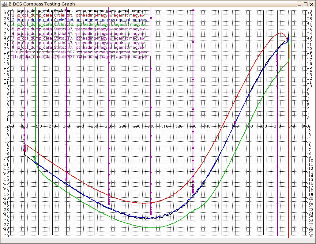
@NineLine In another thread about the compasses in the Mosquito (here) we've had a similar discussion, and the repeater compass in the Mosquito shows similar behaviour. In that case there's also a P8M compass in the cockpit which does adjust for pitch and bank (up to 10 degrees) and that compass shows a much smaller error due to the pitch nose-up on the ground, so the two compass readings are usually different (unless you're pointed to magnetic north or south). I did some testing to work out what the compass heading shown by the repeater was, and am reasonably confident that it's behaving as if fixed in the airframe with no gimbal or float to allow for pitch and bank. Whether this is realistic or not we're not sure about, but kablamoman's documents here suggest that at least for the P51 the repeater compass should have a pitch/bank allowance from the float. I think the repeater compass on all modules I've tested shows what I call the 'aircraft magnetic heading' (abbreviated to ACMagHead or acmaghead in my test results below). This is the magnetic heading obtained by setting up a vector in the magnetic field direction from the declination and inclination values, then rotating it to the aircraft coordinates by rotating through the heading, pitch and bank angles and taking the direction from the x- (forwards) and z- (starboard) coordinates. This is what I'd expect a simple compass fixed horizontally relative to the aircraft to read. Ie. it looks to me like the repeater compasses have zero allowance for pitch and bank. The maximum difference between this and the magnetic heading measured horizontally relative to the ground is indeed around 25 degrees for 12 degrees pitch. I've repeated these tests now for the P51 and put the results below if they're useful. To perform the tests I've first set the deviation figures to zero in Mods/aircraft/P-51D/Cockpit/Scripts/RemoteCompass_AN5730/compass_param.lua so that there are no deviations affecting the readings. I've then set up a hook script to log relevant data at intervals of approx. 4 times a second to a CSV file and set up a mission with a P51 on a parking area at Anapa with start type set to 'Take off from ground (hot)'. The mission date was left at the default which gives magnetic declination of slightly over 7 degrees east and inclination of 63.2 degrees. With this setup, I've run a number of static tests at fixed headings, where I set the heading in mission editor to 217, 247, ..., 337, 007, 037 giving magnetic headings of 210, ... 030 and left the aircraft static for a few seconds until the compass pointer is steady, then quit the mission and made a copy of the CSV data. I also run two dynamic tests where I taxied turning through around 180 degrees to port and to starboard, and again saved the CSV data. I'll attach tracks for the dynamic tests along with the script used to log the data at the end of this post. From the CSV data, I made up the following graph, which I'll attempt to explain below. All the plotted lines show the difference between a compass reading figure (calculated or measured) and the 'magyaw' figure, which is the horizontal (relative to ground) magnetic heading obtained from Export.LoGetMagneticYaw(). The blue and black plots are the 'ACMagHead' figure referred to above for the two dynamic (turning taxi) tests, which agree apart from small differences caused by changes in pitch because of ground bumps or uneven acceleration, etc. The vertical purple lines, with points shown, are the readings of the repeater compass from the static tests at various angles and show the repeater pointer moving to and settling on a reading at the mission start. The points are at approx. quarter second time intervals. As can be seen, they settle to a final value close to the calculated curve (within a degree or so, where the pointer damping stops the needle movement). The red and green plots show the repeater compass readings from the dynamic tests - turning to port (red) and starboard (green). As can be seen, they generally follow the calculated curve (except for a vertical line where the pointer is moving to its initial heading at mission start), but lag behind it since the pointer takes time to move to the new headings, so that when turning to port the reading is always a bit higher than the calculated heading and to starboard it is always a bit lower. I think these results support my assertion that it's the 'ACMagHead' figure that the repeater compass shows. Here are the tracks of the two dynamic tests: Testing_P51_GroundCirclePort.trk Testing_P51_GroundCircleStbd.trk and the hook script used to log the data (which includes the calculation of the ACMagHead figure): jb_dcs_dump_data.lua and here are the CSV files containing the logged data produced by the two dynamic tests: jb_dcs_dump_data_CirclePort.csv jb_dcs_dump_data_CircleStbd.csv
-
investigating Cannot calibrate Gyro with Mag Compass
JBDCS replied to Nealius's topic in Bugs and Problems
I don't know if this is of interest, but here's a document I found when doing an internet search for info on the repeater compasses. It's a report from 1945 "Review of Remote Indicating Systems for Aircraft", covering various R.I. devices including compasses. I haven't read it in any detail, but it looks like there's some information on how flux gates were used at that time in it. https://reports.aerade.cranfield.ac.uk/bitstream/handle/1826.2/3199/arc-rm-2199.pdf?sequence=1&isAllowed=y [Edit: On having a look at it and searching for "flux gate", it's only mentioned with respect to one particular transmission method. Whether that's relevant to the repeater here I don't know. In fact it looks like it is, since it is the Magnesyn transmission method mentioned by kablamoman.] (Found this document, which is in the UK Cranfield University Aerade archive, via a link from a radio forum thread which the search turned up: https://www.vintage-radio.net/forum/showthread.php?p=1488845 Looks like there may be other interesting stuff in the Cranfield archive, but I've not had chance to look at it yet: https://reports.aerade.cranfield.ac.uk/) -
Looking for a real Mosquito compass deviation card, anyone?
JBDCS replied to Lau's topic in DCS: Mosquito FB VI
Thanks for the thread link kablamoman, I hadn't seen that thread but as you say it seems to be describing exactly the same problem in the Mustang (just from a quick look so far - I'll give it a proper read sometime soon). -
Looking for a real Mosquito compass deviation card, anyone?
JBDCS replied to Lau's topic in DCS: Mosquito FB VI
My guess would be no, not like that in reality, but since I don't really have any knowledge of it it's just a guess. -
Looking for a real Mosquito compass deviation card, anyone?
JBDCS replied to Lau's topic in DCS: Mosquito FB VI
Yes the R.I. Compass Repeater is certainly the easier instrument to read but one important note is that that one does read as if the compass it repeats from is fixed in the airframe and not gimballed at all, so with that one it's even more important to make sure you're flying dead level when reading the compass because without a gimbal the reading will be affected a lot by pitch and bank. For example in my test results detailed earlier in this thread for the P8M at various headings on the ground, with the aircraft pointed east or west there is a couple of degrees error due to the pitch up being more than what the compass can handle. For the repeater compass, this same test gives an error of more than 20 degrees in heading at 11 degrees pitch, which is what would be expected if it's fixed in the airframe. I've tried adding a max_pitch_bank line to that compass setup file, but it seems to have no effect, so looks like it's not that simple to set up. This is a bit strange when the DCS flight manual says during engine warmup to check that the P8M and repeater compasses agree and to set the gyrocompass from them, since on the ground as it is neither of them will usually read correctly and there will usually be a difference between their readings, often quite large. There's no information in the manual about the compass device which the repeater reads from, so no idea whether this is realistic or not, but someone will perhaps know more. -
Looking for a real Mosquito compass deviation card, anyone?
JBDCS replied to Lau's topic in DCS: Mosquito FB VI
Yes I agree, nice to get things right and great that the game/sim takes these things into consideration, but can any of us really fly that precise a heading? -
Looking for a real Mosquito compass deviation card, anyone?
JBDCS replied to Lau's topic in DCS: Mosquito FB VI
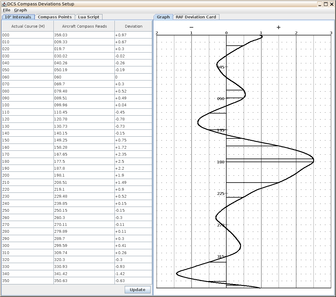
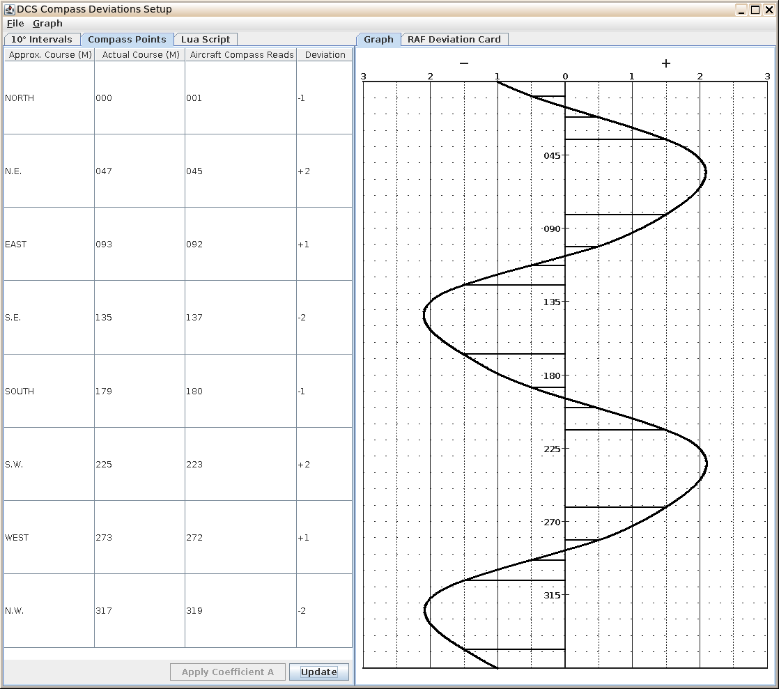
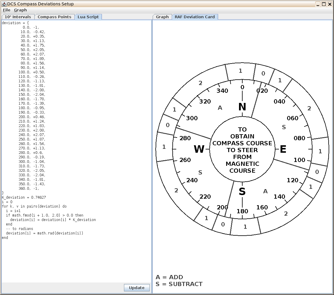
Okay, first off sorry I've not posted back for a while, I have continued testing things out though. The testing is very complicated (or maybe I'm overcomplicating it) because: it's very difficult to read the compass(es) accurately in the cockpit the readings are affected by pitch and bank as I've already mentioned the readings are also affected by inertia effects making the needle move around I've now worked out how to get the compass readings from the devices in game and log them to file along with the other heading information, so that fixes the first problem, but the other two still make things difficult. Anyway, by doing that and graphing out the differences between a setup with zero deviations and one with deviations set I think I'm reasonably happy that it is working how I expect (I'll put more details of that in another post sometime). So now that I've got that far, I've started work on a program for playing with the setups, and generated some deviation settings to simulate the readings for the Manchester in the 1944 RAF manual (p190). It's still very much work in progress, but the screenshots below should show what I'm aiming for, and at the end I've listed the deviation settings you could use in your scripts for these deviations (though I've not actually tested those settings yet). The first screenshot shows the deviations from the standard Mosquito compass_device.lua. These are the generic deviations which seem to be used across all modules in game. It shows the deviations against each course in steps of 10 degrees, along with a graph in the style of the RAF compass log graph on p191. The second screenshot shows the deviations for the Manchester, entered manually against the compass points, and adjusted for coefficient A (ie. the deviation figures match those in column vi in the manual), alongside the graph for those deviations. The only difference is that the table in the manual has north west first but my table has north first so that the rows line up roughly with the graph. The third screenshot shows the same data as the second, this time showing the deviations script which can be used in the device .lua files to set these deviations, and on the right a compass deviation card in the style of the card described also on p191. [Note: I realised after taking this screenshot that the deviation figures in the lua script are wrong - they should all be divided by the K_deviation value, since they're multiplied by it after that). I've fixed it now in the script at the end of this post, but this screenshot still shows the incorrect values. Also found that lua does not accept numbers beginning with +, so have removed those in the script too but again on this screenshot shows the old version.] (I haven't worked out yet how to suitably position the ADD and SUBTRACT labels, so for now the card just shows A or S.) The idea is that images of these graphs and/or cards can be added to the kneeboard or somewhere else. I'll also add the USAAF style deviation card from that manual (which is just a simple list) and maybe other formats later. Anyway, if you want to try playing with these deviations, here's the code you need to copy and paste into your compass_device.lua and/or remote_compass_device.lua files, replacing the similar existing code (but see the warning below this code): deviation = { 0.0, -1.34, 10.0, -0.56, 20.0, 0.47, 30.0, 1.52, 40.0, 2.35, 50.0, 2.75, 60.0, 2.77, 70.0, 2.53, 80.0, 2.09, 90.0, 1.53, 100.0, 0.77, 110.0, -0.34, 120.0, -1.52, 130.0, -2.43, 140.0, -2.79, 150.0, -2.73, 160.0, -2.39, 170.0, -1.87, 180.0, -1.28, 190.0, -0.44, 200.0, 0.62, 210.0, 1.67, 220.0, 2.46, 230.0, 2.79, 240.0, 2.77, 250.0, 2.51, 260.0, 2.07, 270.0, 1.52, 280.0, 0.8, 290.0, -0.26, 300.0, -1.39, 310.0, -2.31, 320.0, -2.75, 330.0, -2.74, 340.0, -2.42, 350.0, -1.92, 360.0, -1.34, } K_deviation = 0.74627 i = 0 for k, v in pairs(deviation) do i = i+1 if math.fmod(i + 1.0, 2.0) > 0.0 then deviation[i] = deviation[i] * K_deviation end -- to radians deviation[i] = math.rad(deviation[i]) end WARNING - If you edit the compass_device.lua files, they will fail the integrity check (you get messages in dcs.log about IC fail for those filename), so be sure to make a backup copy before editing them so that you can copy that back if you want to run on multiplayer servers which enforce the IC. I think this also means that your modified files will be moved to a backup folder when the game is updated and the files would revert to the standard ones, so you'd need to copy your modified version back into the game directory after updates.
-
Looking for a real Mosquito compass deviation card, anyone?
JBDCS replied to Lau's topic in DCS: Mosquito FB VI
Sorry to correct your correction, but I think I was right in my guess, though it was just that at the time. I've had a bit of a look at that section of the 1944 RAF manual, and this covers it I think: "(a) From these eight deviations , calculate coefficient A. Loosen the compass fixing screws , and remove A by rotating the whole compass that number of degrees in the appropriate direction (clockwise if A is +, and vice-versa) . Re -tighten the screws. Coefficient A should be corrected only if of the order of 1 1/2° or more , and then only on the authority of the responsible navigation officer." So in their example, coefficient A is +3 so should be corrected by a compass rotation, to leave the column vi figures. -
Looking for a real Mosquito compass deviation card, anyone?
JBDCS replied to Lau's topic in DCS: Mosquito FB VI
Okay not read you full post properly yet (will do tomorrow), but unfortunately I don't think anything like the above paragraph is possible in game (if anyone can correct me, please do). The deviations are, I think, baked into the .lua scripts for the aircraft and loaded at mission start, so will be constant through the mission, and unchanged by dropping ordnance etc. As I say, I'd be happy to be proved wrong. No, no problem at all. That just means that with the generic profile it looks like they're using, the maximum compass deviation is 2.5 deg. You can make it as big or small as you want. -
Looking for a real Mosquito compass deviation card, anyone?
JBDCS replied to Lau's topic in DCS: Mosquito FB VI
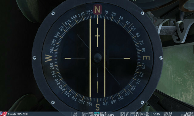
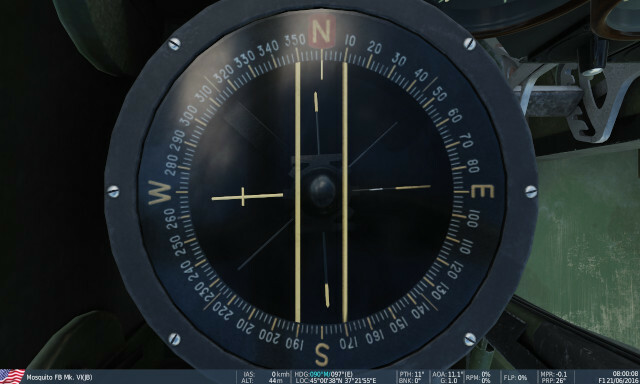
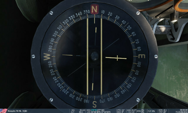
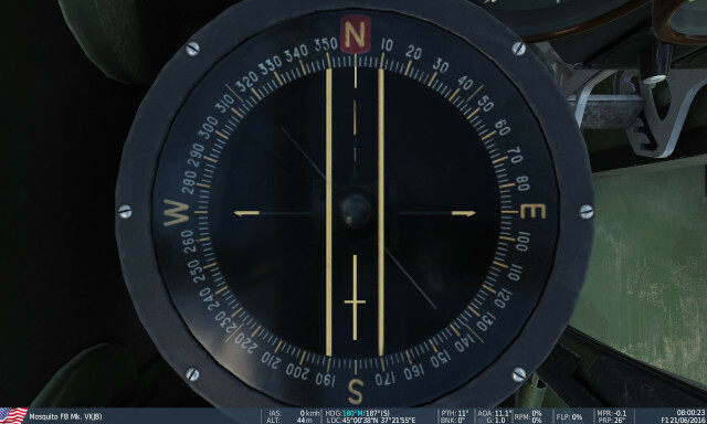
Okay I've started a bit of testing now with the Mosquito on the ground. Not got as far as playing with compass deviations yet - I've got them set to zero for testing in my compass_device.lua script - but been investigating my comments a few posts up about how pitch and bank affect the compass. I'm glad to say that I was wrong in saying that the game works as if the compass was fixed in the airframe rather than floating - from testing with the Mosquito it looks like the pitch and bank do not affect the compass reading for small enough angles, so things are working as they should. This is controlled by another setting in compass_device.lua, max_pitch_bank = math.rad (10), which tells it the the first 10 degrees of pitch and bank are handled by the compass needle levelling, so should not affect the reading. However, the Mosquito on the ground is pitched up at 11.1 degrees, so there is still an effect seen on the ground when not aligned to magnetic north or south. I'll put some details of my testing in a spoiler below so people who are interested can have a look, but the short advice for Mosquito navigation based on the results is that you should only take note of the compass readings when you're within 10 degrees of level flight. It's good that DCS models the compass in this kind of detail.
-
Looking for a real Mosquito compass deviation card, anyone?
JBDCS replied to Lau's topic in DCS: Mosquito FB VI
@average_pilot Yes I think I see what you mean, and it's one of the quirks of DCS terrain maps. The maps are set up on a rectangular grid, as usual in real maps, which doesn't necessarily align with true north (again as in real life). In our case the map north, which I call Grid North, as indeed they do on UK Ordnance Survey maps is the equivalent to our x and z coordinates in-game (y is the "up" coordinate, x is north and z is east). This is the grid and coordinates on the F10 map. The latitude/longitude lines can be shown/hidden in Mission Editor by going into the map options and toggling Geographical Grid, and from those you can see that the geographical (ie. true) north is aligned differently from grid north to different degrees at different points of the map. The ruler in Mission Editor and (I guess though not checked) the F10 map is simply based on the grid coordinates. The magnetic declination will also vary across the map. These can be obtained from a magdecl lua library, which will calculate and cache the magnetic declination and inclination for all latitudes/longitudes at any date, based on magnetic field models. I think in real life (though see note below) magnetic declinations are normally given relative to true north, but in game I'm pretty sure they're applied to the grid north. This means that if you fly a long way west-east or vice versa, true north in game will shift significantly, but the in-game grid north will not change and the magnetic declination will only change slightly. In real life, the magnetic declination would be applied relative to true north, so that would also shift in the same direction, which does not happen in game. Note 1: I just checked a UK OS map which was to hand (1:50,000) and in that case the magnetic declination IS given relative to grid north. However that's a walking map rather than a flying one, and the relative movement of true north across the map is likely very small, as opposed to a map covering hundreds of km / nm. When I get time I'll have a look at OS maps of different areas for the same date and see how they vary. The map key gives details of true north vs grid at each corner (in this case, grid north aligned with true on the western edge, and just under half a degree difference (true W of grid) at the eastern edge). Note 2: I need to do some experiments in game to check out the above claims - as I've said I experimented with various compass bearing tests in he past but not recently. I think it may be a good idea to start a new thread in a general section for discussions like this about magnetic compass navigation, where we can share info on how things work in real life and in game (but keep it free of various ADF/radio navigation info), because we're getting fairly off-topic I guess. Hopefully in the next few days I'll get chance to experiment and confirm (or otherwise) what I found last time I looked, and will maybe start a new thread and if so will post a link here. I guess (at least hope) this kind of thing is a big part of the projected 'Whole World Map'. Which makes me think of note 3 below: Note 3: I haven't tried any navigation stuff out in the southern hemisphere yet, eg. the South Atlantic map - got the map but hardly dare trying navigation out! Then there's the upcoming Kola Peninsula map for higher latitudes northern navigation. -
Looking for a real Mosquito compass deviation card, anyone?
JBDCS replied to Lau's topic in DCS: Mosquito FB VI
Looks like you can download an offline PDF of stuart666's 1944 manual here, in case you haven't found this yourself: https://www.google.co.uk/books/edition/Air_Navigation/WbJ8AAAAIAAJ?hl=en&gbpv=0 Not spotted any volume 2 though I'm afraid. Some different contents in this 1944 copy from the 1935 copy you linked to by the look of it. Thanks again to both of you for the links anyway, I've got lots to read now. I found this one by browsing the search results for Great Britain. Air Ministry in Google Books, lots of interesting stuff there (from the book link above, pick 'Search on Google Books' under the Author on the right). -
Looking for a real Mosquito compass deviation card, anyone?
JBDCS replied to Lau's topic in DCS: Mosquito FB VI
Thanks both of you for those links. Lau, yes I could have a go at setting up any deviation figures in the set up files. I was actually thinking of trying to set something up based on that Manchester card for testing to try out their calibration procedure, ie. set it up so that the compass gives the readings listed on the card, then make the adjustments step by step as they do, by adding/subtracting from the figures in the deviations setup .lua file, to get to the final deviations in column vi. One complication which I haven't mentioned yet, is the way DCS handles the magnetic inclination (rather than declination), ie. the vertical component of the magnetic field. Because taildragger aircraft are always pitched up when on the ground, if the compass is fixed in the aircraft this component will also affect the compass reading except when the aircraft is pointed to magnetic north or south. In practice I think the compass usually has a gimbal or a floating needle to handle this and read correctly for small pich/roll angles, but the last time I looked at it (a few years ago admittedly) they seemed to be reading as if fixed. This complicates things a lot when testing the compass on the ground. I'll have to have another look at it sometime. Not sure when I'll get time to look at this though. Hopefully fairly soon. -
Looking for a real Mosquito compass deviation card, anyone?
JBDCS replied to Lau's topic in DCS: Mosquito FB VI
Okay thanks stuart666, so if I'm interpreting it correctly that is showing the method the ground crew would use to set up the compass so the deviations were minimal, then the remaining deviations (which we would set up in game) are the figures in column vi of the second table. PS. Is that Air Ministry Navigation Manual online somewhere? Sounds interesting. -
Looking for a real Mosquito compass deviation card, anyone?
JBDCS replied to Lau's topic in DCS: Mosquito FB VI
I looked at this a long time ago, not for the Mosquito but for the FW-190D9 IIRC, but the setup is the same for all modules I think. The per-aircraft compass deviations are set up and working in game (or at least they were, not looked at them recently), but they are really than per-type rather than per-individual aircraft. In the Cockpit/Scripts directory under each module (most of them at least), there will one one or more .lua files containing a table and variable deviation = { ... } K_deviation = ... where the deviation table contains the deviation figure for each angle from 0 to 360 degrees. The bit of code after that multiplies the deviations by the K_deviation factor, so that can be used to adjust the deviation strength for all angles. Eg. for the Mosquito there are two files containing this table, compass_device.lua and repeater_compass_device.lua, presumably for two different instruments (I've not flown the Mossie for a long time and can't remember what instruments it has). [Edit: Just had a look at the manual and they are the main Magnetic Compass and the R.I. Compass Repeater.] However, the deviation table always contains the same figures (on all modules I've looked at at least), and the K_deviation factor is usually the same too (0.74627), so it looks like they just use a generic deviation table across all modules, but you could edit the tables to create per-type deviations (though not for individual aircraft). To see that this is working you can edit these .lua tables and see the effect in the cockpit. Eg. if you add 10 to each of the right-hand figures in the deviation table, you should see the compass direction moved by 10*0.74627 = approx 7.5 degrees the next time you use that aircraft type. If you add 10 to the figures for a range of angles and leave the others as they are, the compass will read 7.5 degrees differently from standard when you're in that range of magnetic heading angles, but the same as standard otherwise. If you just change one of the two files, the two instruments will read differently where you've changed the values in one. And back to the OP, it would be very interesting to see an original deviation card, and to set something similar up in game. -
Thanks funkyfranky and Chump - the magvar library described in the thread linked to by funkyfranky does exactly the same as my own dll, so there's no need for mine any more. If there's a problem using require to include it in mission scripts, I think the same problem would be there with my own dll, since you'd need to use require to include that too. So hopefully there's a way round that. I've just tested the magvar library out from a hook script, and it works fine that way (and, I'm glad to say, gives the same results as my own dll does). Note: as well as the get_mag_decl (lat, long) function in the magvar library, there's also get_mag_incl (lat, long) to get the magnetic inclination if that is needed for anything (probably not).
-
I've looked at this myself before (probably a few years ago) and didn't find any way of getting the info through the standard lua script API functions. The data needed is stored in the files in Data\MagVar\TabularData under the Saved Games DCS folder - the data in each of these files covers the whole globe for a given year/month, and the files are created during mission load if there is not already a file for the relevant month. They are binary files though, so not too easy to read in lua scripts. I wrote a lua dll file to read them, which works well for my purposes (mostly used via hook scripts). I could upload it to the user files if you want to give it a try and see whether it does what you want. I've not done much with mission scripting at all, so don't know how easy it is to include functions from a lua dll in them.
-
reported Key-binds for RSI-6K receiver tuning knob not working
JBDCS replied to Lixma 06's topic in Bugs and Problems
I've just been learning the MiG-15bis and run into the same problem with the keybinds for the radio commands. It's not just the controls for the receiver tuning, but the other RSI_6K commands too, on the transmitter control panel at the back of the cockpit as well as the receiver control panel on the left. Some of the commands do nothing obvious, while others move different controls - as Blackbird7 says, if you set up a keybind for the Wave Control Handle, that one actually moves the receiver tuning knob, though because in DCS that's linked to the wave and antenna control handles they are moved too. After a bit of experimentation, I've found that all the device command values used in the down/up/pressed/action settings for the RSI_6K in the input config files are out by 1. These command values come from the RSI_6K_commands list in Mods\aircraft\MiG-15bis\Cockpit\Scripts\command_defs.lua. If this file is edited to add a dummy command entry between the clickable cockpit commands and the keyboard/joystick input commands, as follows: ... Mig15_Command_RSI6K_AntennaFrequencyFix = counter(); Mig15_Command_RSI6K_ReceiveARC = counter(); Mig15_Command_RSI6K_Forced = counter(); -- Added line to fix command number sync. Mig15_Command_RSI6K_Dummy_Fix = counter(); --input commands Mig15_Command_RSI6K_SetReceiverFrequency_EXT = counter(); Mig15_Command_RSI6K_SetTransmitterFrequency_EXT = counter(); Mig15_Command_RSI6K_SetAntennaFrequency_EXT = counter(); ... the commands then work correctly and the keybinds control the correct handles/buttons, etc. (In fact the added line could just be counter(); without making up a dummy command name for it, but it's probably clearer if it has the same format as the other lines.) With this change the keybinds are all working for me now, but I still need to do further testing to see whether I can tell if the radio is actually working properly. I've already noticed that the receiver frequency/wave number shown in the kneeboard doesn't change when the receiver is tuned either by using the keybinds or turning the knob via the clickable cockpit. Whether that means it's not actually tuning the radio and is just moving the dial I'm not sure. (The transmit frequency/wave number in the kneeboard does change correctly when the handle is moved either directly or through moving the receiver tuning.) EDIT - To correct the last paragraph, I've just worked out that the receiver frequency/wave number in the kneeboard (and on the dial on the back-left of the cockpit) does not update when the radio power is off on the circuit breakers. With the power on the figures do update. (I was testing it in a cold start mission with no power, and without power the kneeboard transmitter figure updates but not the receiver figure.) -
Another good place to search for ruins is just to the west of Akrotiri in Cyprus - fly northwest along the coast then when the coast turns westwards there's some hills just inland with lots of ruins. Called Ancient Kourion on Google Earth. Also worth checking out on Cyprus is Famagusta, on the coast northeast of Kingsfield / southeast of Gecitkale, with the city walls, Othello Castle and mosque. I'm sure a lot of the features in the ruins are common assets - the amphitheratre in the middle of the Aleppo ruins looks very similar to the one near Akrotiri, and I've seen the same object on the north coast of Cyprus too - but it's still great to find and explore them. And the Huey is a great aircraft for doing it.
-
Here's the spreadsheets - second time lucky, worked okay now I think. InclinationGroundTest_BatumiA8.xlsx InclinationGroundTest2.xlsx
-
I've been looking at where the magnetic compass figures come from in the sim for a while now, and think I'm getting close now, and this morning I've managed to recreate the compass readings from the warbirds on the ground using my own calculations (well, only tested it for the FW190-D9 and A8 so far, but for those two at least; still need to test it out on the others). Going back to the opening post, I'm now pretty sure the reason the compass (or the repeater) gives confusing readings is because of the magnetic inclination, ie. the dip angle of the magnetic field towards the ground. This is a significant angle, more than 60 degrees for the Caucasus, and is what affects the compass on the ground since the nose-up pitch of the aircraft means that (unless pointing directly magnetic north or south) there's a component of the field pulling the needle further east or west. As Ramsay says, if the compass is gimballed so that it stays horizontal this shouldn't happen for small angles, but from my experiments it seems like this isn't modelled - I get a good agreement with the actual readings if I assume the compass is fixed in the plane of the aircraft. I've only been testing the figures on the ground - it's too difficult to take exact readings while flying unless I can find a way of getting the actual compass reading logged - so there may be further lag effects due to movement as well, but I haven't noticed any lag in the changes qualitatively while flying so I suspect not. Here's a quick description of my method: - I get the magnetic declination (variation) and inclination figures from one of the files under Data/MagVar/TabularData in the DCS Saved Games folder. These files are created at mission start if one does not already exist for the month and year of the mission, cover the whole globe and contain declination and incliniation at each whole-number latitude and longitude. I've written a small Lua library which calculates the figures for a particular decimal lat and long by linear interpolation and read them in scripts, which I can release if people are interested. The declination can also be got from the functions in Export.lua - there's a function LoGetMagneticYaw which returns the heading adjusted by the declination - but I haven't found any other way of getting at the inclination figures. - From the declination and inclination, I make up a unit vector in the field direction in DCS world units (ie. x = map north, y = up, z = map east). - I then transform this vector by three rotations: First by the heading. After this rotation, the angle of the x-z component of the vector is the 'MagneticYaw' figure mentioned above. Next it is rotated by the pitch angle, then finally by the bank angle. This leaves me with a unit vector for the magnetic field relative to the aircraft coordinates (x = fore, y = up relative to aircraft, z = starboard). - An arctan of the resulting x and -z coordinates should give the compass reading (ignoring the deviation due to the aircraft, which is modelled, but I won't go into in this post to avoid it getting even longer). To illustrate this, I've attached a couple of spreadsheets which you can look at if you like. One is a test I did using an FW-190D9 at Mozdok, where I made notes of the compass readings when parked in the middle of the runway at all angles (in 15 degree increments). I had a telemetry script logging a few values, and using these values along with my method outlined above get a result very close to the readings I made in the cockpit - within +/-1.5 degrees, which is about as accurately as I can read the compass. The second spreadsheet is one I've just done doing the same thing but with just one entry, for the same details as Nealius's opening post, ie. Batumi, 2016 (June), takeoff from parking hot, parking bay 10, which gives an infobar heading of 305, so expected magnetic if the aircraft was level would be 299.5, but after adjusting for pitch and bank the calculated reading is 279.1 - pretty close to the 280 degrees shown. EDIT: I just tried attaching the spreadsheets but it didn't seem to work - the first just said 'uploading' and the second 'queued', and no change after a while even though only small files. I'll try again in fresh post shortly (bit of a forum newbie I'm afraid).
-
Yes, Danish_Squid, that's how it works by default. My query was whether that could be disabled, since using VR you don't want it to change your viewpoint - it's like your virtual head position moves even though you know your real head doesn't, and you need to recentre the VR position afterwards to get your head back where it should be. Changing the cockpit camera origin to Cruise for the BF109 in the Special tab of the settings stops it moving the viewpoint, which is what I wanted.
-
Yes, it works as it should (as far as I can tell at least). The reticule image is at infinity so appears in the right place regardless of your head movements, and you can use either eye (as long as you move so that the reticule is in the area of the sight). And as I've now noted above, now that I've tried Teo's tip for the BF109 it doesn't move your viewpoint around when you flip the gunsight up any more.
-
I've just started flying the BF109 too, and must say the offset position is a bit strange in VR. Sure you can reset the view how you want, but when you fold the gunsight up/down it moves your viewpoint a bit to the right/left, which just feels odd in VR, where if you want to move your viewpoint you just move your head. Any way to switch that feature off that I've not noticed? Apart from that, it feels good to fly - only just worked out how to start up and take off so far though, been learning on the FW190 for a while (and still not great at that), so quite a different machine though a lot of the instruments are familiar. Edit - now I re-read this thread, I haven't tried Teo's suggestion of changing the camera origin option in the 'Special' tab for the 109 - I'll try that next time I fly it. Edit 2 - tried it yesterday with the Cockpit Camera Origin set to Cruise, and yes, that does fix the position movement when you flip the gunsight up/down in VR, so thanks to Teo.