Search the Community
Showing results for tags 'a8'.
Found 7 results
-
Hi all I have seen time and time again the request for more boost and various systems for achieving higher ata on the Focke-Wulf 190 A8. Now I have also seen some confusion surrounding these systems leading to some threads being closed and tagged with a "should come with a future variant." My hope is to sort out some of that confusion and maybe get the proper system modelled within DCS. System number 1: MW50. This is the same standard 50:50 mix of methanol and water that most late war German fighters see. I won't get further into detail as this method was tried, passed over and later gone back to due to a fuel shortage but was not the first pick for the 190 due to a small rise in cylinder head cracks. System number 2: C3 Injection. This method took extra fuel and injected it directly into the supercharger which was able to increase the ata to 1.58 in the low supercharger gear and 1.65 in the high gear at altitudes under 1000m (3281ft). This method was designed and used on variants used as fighter bombers such as the F8/G8. Thus this system may be a viable option for those aircraft when they are released but not for our current fighter variant. (Page 82 of the Haynes Focke-Wulf Fw190 1939 onwards (all marks) owner's workshop manual) System number 3: Erhöhte Notleistung. This method is by far the most relevant to the current model of Anton we have. During 1944 this method was developed and "controlled by inserting a pilot-operated stop cock in the pressure line of the boost regulator, with the effect of overriding the supercharger boost pressure regulator to allow a short-term boost of supercharger power." (Page 82 Haynes...) Now this system is further outlined in the Official FW190 A8 handbook linked below. Part 6 of the handbook outlines the C3 injection system and then talks about the Erhöhte Notleistung stating: "A newer method of increasing the emergency speed of the fighter has been to insert a pilot operated stop cock... When this system is incorporated supplementary fuel injection is no longer necessary and is, therefore, omitted." This clearly states they are two separate systems one being favored over the other. In Part 7 section C. this new "Emergency Power System" is outlined. "The increased power is gained by bleeding air from the supercharger pressure line (6,1), in which are located two nozzles connected in series. A flexible tube (6,2), through which a portion of the boost air can be drawn off off when the valve (6,3), is opened, is connected into the supercharger air line between the fuel mixture chamber and the boost pressure regulator. The two nozzles, the first of which has a smaller inside diameter, are so constructed that when the actuation valve (6,3) is opened, the air pressure within the boost pressure drops to a very low level; this causes the throttle valve to open wide, thereby increasing the maximum obtainable boost pressure, at 2700 RPM, from 1,42 ata, to 1,58 ata at the low supercharger setting, and to 1,65 ata at the high supercharger setting. The higher boost pressure results in in increased fuel consumption, due to the greater quantity of fuel injected into the cylinders." Now unlike the the C3 injection system this does not have an altitude restriction as it is not injecting fuel directly into the supercharger and enrichening the mixture without proper accounting for the fuel to air ratio. This system does have increased fuel consumption as the mixture is increased appropriately through injection into the cylinders to account for the increase in air consumption as well with the higher boost pressures. This system is simply overriding the boost pressure regulator and "tricking" the throttle valve to open to its fullest extent. ONE LAST TIME this is not a C3 injection system, it does not directly inject fuel into the supercharger, it does however manipulate boost pressures and "trick" the throttle into opening wider. (This is the figure from the Official A8 handbook note its lack of injection into the supercharger and the lack of fuel lines in general. It is only manipulating boost pressures.) Lastly it is noted in the Haynes publication on page 83 that "in early 1945 orders were given that limited time emergency power for fighter variants (A series) could be achieved by a simple manifold pressure boost to 1.8ata, giving the equivalent power boost to around 2,400ps." (2,367hp). I am not arguing for the inclusion of this as it doesn't make clear if this was a result of MW50 or the Erhöhte Notleistung system, it makes it sound like the Erhöhte Notleistung is the system used but I have no backing evidence and that seems to be unrealistic as I can find performance charts with 1.58ata and 1.65ata but not 1.8. Interesting to note though. Links: Official Focke Wulf 190 A8 handbook (english translation) http://lexpev.nl/downloads/fw190a8.pdf Unfortunately I am unable to find a PDF of the Haynes publication but here is a picture of the cover so you may find the proper book if you wish to purchase it like I did. (ISBN: 978 0 85733 789 4) This publication sites the original manual many times but keeps a ton of information all in one place Notes: I did go back through to try to eliminate repeating information. I apologize for the length but I wanted to draw the distinct difference between the systems as I have seen them be confused one for the other. The A8 is a true passion of mine and I only wish to see it modeled to its accurate capabilities and not continue to see it be put down as these systems are incorrectly assumed to be the same. If anyone has any questions or further information please ask I will be paying attention to this thread. Some have already pointed to this system but I have not seen anyone explain how the system works or what it is simply that it is. My hope is this clarifies the matter.

- 68 replies
-
- 21
-

-

-
- gimme dat boost
- 1.58ata
- (and 4 more)
-
 Pretty much as in the title. If the uplatch for either gear leg is destroyed, that gear leg will drop. However as I understand, even if the latch is destroyed, the motor for the gear leg will operate in order to keep that gear held up....even if it's not locked. At the moment, either the motors are somehow broken automatically when uplatches are, or the motors simply don't function once the gear was successfully raised once. An example for what I'd expect would occur is the Dora. For the Dora within DCS, if you destroy or disable the uplatches for both gear legs, the gear will remain up and retracted. The load on the motors will also increase if you pull intense G-loads, and this will actually cause the gear's weight to overcome the strength of the motors, and the gear will momentarily peak out, before retracting back up when the aircraft stops pulling G. All of this isn't the case with the Anton, as of now. Of a slightly different note, it seems that the Dora's gear motors also don't burn out. You can destroy the D9's uplatches, causing the motors to constantly run, and they will continuously operate for at least 40 minutes. I haven't tested it for a longer period of time. But this is, again, on a slightly different note.
 -
I'm going to preface this with a one-stop summary: This is a post arguing for already-made and available liveries for the Fw-190A8 to be added to DCS officially for broader usage to the playerbase in singleplayer and online, allowing other players to use and see them. Download options are available at the bottom of this post. Who: The skins are made by myself. I have been within the DCS community for a good number of years, since the Dogs of War server (when there was only the P51, Fw190D9, and Bf109K), and almost all of it was within the WWII side of DCS. Of mission makers and server runners today, like the 4YA Project Overlord server, one of the most reoccurring complaints from mission designers is that we do not have a historical livery selection for the Fw190. This has been noted by the player base of late. Having been around these complaints and criticisms for some time, within that context and that of the required time period and location, I've created a set of liveries for the Fw190A. What: We do not have a single historical and relevant livery for the Fw190A8 in DCS at this moment. Of all the chosen liveries from the Fw190A8's livery contest, none of them are historical, or relevant to France in 1944. Some of them do not have working bort numbers. A couple are Japanese Zero cosplays. And some are only relevant to earlier versions of the Anton. There is a big deficit in DCS for a historical livery set for the Anton 8. To attempt to remedy this, I have created liveries for JG26 and JG1 in their summer 1944 configuration. I'm proposing that Eagle Dynamics incorporate some of these liveries into DCS officially. This will give the simulator its first historical liveries for the Fw190A8. There are 6 liveries (different Staffeln) of the JG26 to choose from, and 4 from JG1. One may argue that an individual can install any liveries he may choose from the Userfiles and use those. However, this has some severe limitations: 1) Other players online cannot see your livery unless they, by pure coincidence, have that livery also installed. That is very rare. 2) Our most popular servers have the Liveries locked. They cannot be changed by the player, only the mission designer. So it benefits everyone more if these new liveries are added to the official DCS install. Then everyone has them as standard, and it can be used and seen by everyone. Historical Context: The Liveries: Here I have a livery for 2./JG26, 4./JG26 5./JG26, 6./JG26, 7./JG26, and 8./JG26, comprising of half of I./JG26, and all of II./JG26. For JG1, I have 1./JG1, 2./JG1, 3./JG1, and 6./JG1, consisting of most of I./JG1 and a Staffel from II./JG1. I made some special features for these liveries. 1) the camouflage tones, specifically RLM 70, were adjusted to be a more realistic darker color tone 2) each livery has a slightly different camouflage pattern on the fuselage. If you look closely you can see the differences between each livery 3) the bort numbers are custom drawn, and weathered to better suit the weather-worn nature of the aircraft First and second Gruppe, JG1. The JG1 identify themselves by their red tail band and unit emblem on the cowling. 1./JG1, which often included additional ID paint on the underside of the wing tips: 2./JG1: 3./JG1: 6./JG1: First and second Gruppe, JG26. The JG26 identify themselves by their yellow rudder, and the II./JG26 by the inclusion of a horizontal bar. The bar and ID numbers change depending on the Staffel within that Gruppe. 2./JG26: 4./JG26: 5./JG26: 6./JG26: 7./JG26: 8./JG26: Downloads: I have given these liveries a tiered choice to be included into DCS. A first top 5, and a second top 5. There are two options for how to download 1) Standard download. Each livery is individual, and individually includes all the textures it requires. This includes, due to the adjusted camouflage tones, the left and right wings. Disk space consumed for all 10 liveries: 666MB. Standard download HERE. 2) Reliant download. Each new livery is dependent on the 1./JG1 livery to acquire the left and right wing textures, instead of locally. This requires the 1./JG1 livery to be included, in order for other chosen liveries to work. However, this more smartly uses disk storage. Disk space consumed for all 10 liveries: 282MB. Reliant download HERE.
- 30 replies
-
- 14
-
-
-
Noticed that the trim gauge does not have its glass cover during some retexturing for the gauge face glass. This pink appearance was a solid color fill on id_13_D_FILTR, which doesn't bring anything up on the trim gauge. Also noticeable by looking at the default/unedited gauges at a sharp angle. Comparison between the default RPM (U/min) gauge at an angle and the trim gauge at an angle:
-
So ordinarily for cockpit liveries will half work for modules. Either: 1) Modules that come with different language cockpits will have different cockpit liveries for each pre-installed 2) If one was to make a custom cockpit livery as intended, they would create a new folder in Mods/aircraft/aircraft/liveries/Cockpit_Aircraft. When done this way, the livery will appear on the drop-down menu to select in DCS via the Special Options tab in the DCS Menu. However, this will not be practically applied. While the drop down will list your custom cockpit livery, DCS will not render it ingame, and will use the default cockpit livery instead. Thus.... 3) ....to add/create your own cockpit livery, you must overwrite a pre-existing one. This tends to be the cockpit livery called 'default' as is the case with the warbirds. This is already very aggravating to do, as it's a method to work around a broken system that plagues many modules by Eagle Dynamics. See the Apache for a modern example. Now, with the 190A8, none of these options are working. It appears that the module is now ignoring the Mods/aircraft/FW-190A8/Liveries entirely. As to where DCS is drawing its textures for the 190A from, it appears to be Mods\aircraft\FW-190A8\Cockpit\Textures in the "open air", outside of the zipped folder as they usually are. The 190A doesn't seem to be drawing from the textures contained within the Cockpit_fw190_a-8.zip. You'll notice this if you delete the "open air" textures that are outside the zipped folder, and run the 190A in DCS. You'll encounter the Missing Texture, despite the textures it needs being contained in the zipped folder.
-

reported Canopy Glass is Flickering During Head/Zoom Movement
razo+r posted a topic in Bugs and Problems
The external part of the glass is flickering. -
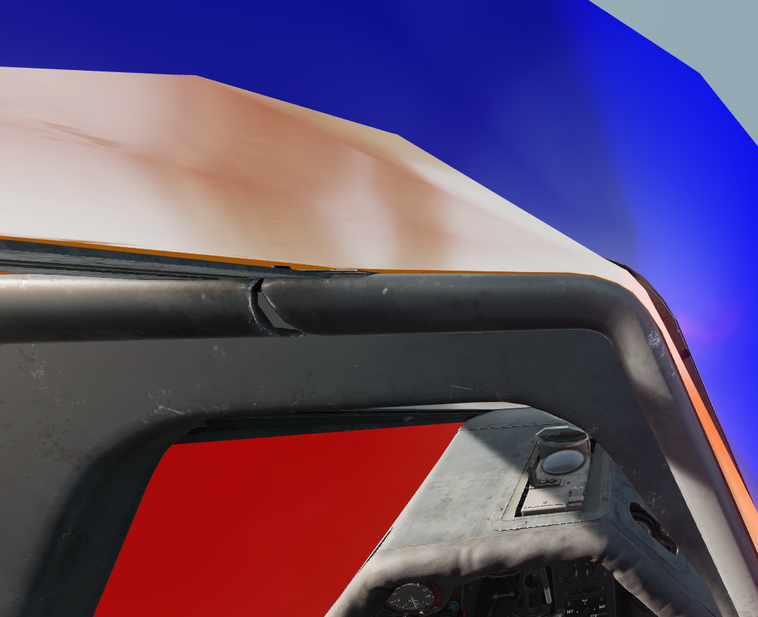
There appears to be some sort of visibility bug with the interior canopy glass material FW_190_GLASS_INT. All textures, to include the diffuse, and the roughmet and probably the glass ('14' in the description.lua) will flicker in visibility when head or zoom movement occurs. Here is a video, after I gave each material's diffuse texture a color (seen in the quotations in the description.lua at the end). If you remove the diffuse texture (set it to empty) so you only show the the glass texture ('14') for FW_190_PLEXGLASS_extr, it flickers with its parent material FW_190_GLASS_INT as well. This does not appear to be due to the interior and exterior planes being positionally coincididal (overlapping), as you can still make out the two if you move the camera inside the glass pane. The glass hue texture (14), which is used on both inside and outside materials: The FW_190_GLASS_INT in red, and the FW_190_PLEXGLASS_extr in blue. Both are visibly separated between inside and outside materials: While I'm using the ModelViewer here since I have more control, there's been folks reporting it occuring during gameplay.
.thumb.png.75e953f67b8523925bacf71be5991065.png)
.png.c33277d03a54ebf97a6606826563194a.png)
.png.988daf30dfd9579e6869e569185507df.png)
.png.21a204103c77a0c43197a9527a1c9657.png)