No1sonuk
-
Posts
1601 -
Joined
-
Last visited
Content Type
Profiles
Forums
Events
Everything posted by No1sonuk
-
I'd try the display one separately on USB, with the others on RS485 first. Also, with them all on RS485, try renumbering them so the display one has a lower number.
-
Looking. Can't see anything major yet. BUT, I think I found an error in 22_Right_Consolle_Displays.ino This part starts at line 210 (under "MAGNETIC DECLINATION"): if ((newValue>=0) && (newValue<6750)){ lc1.setDigit(2,0, 0,false); // No1sonuk - Is there an error in this line? if ((newValue>=2700) && (newValue<4050)){ lc1.setDigit(2,2, 0,true); } } Comment added by me - Should that second line be: lc1.setDigit(2,2, 0,false); I can't think how that could be the issue, but it's an apparent error. EDIT: BTW, have you tried connecting those 4 by USB to see if the RS485 link is the problem?
-
.ino files of all of them, please. It might be something in one, but it could be in more.
-
Hmm. I think we're at the point of asking you to post the code for each device.
-
F-5E simpit cockpit dimensions and flight controls
No1sonuk replied to Bucic's topic in Home Cockpits
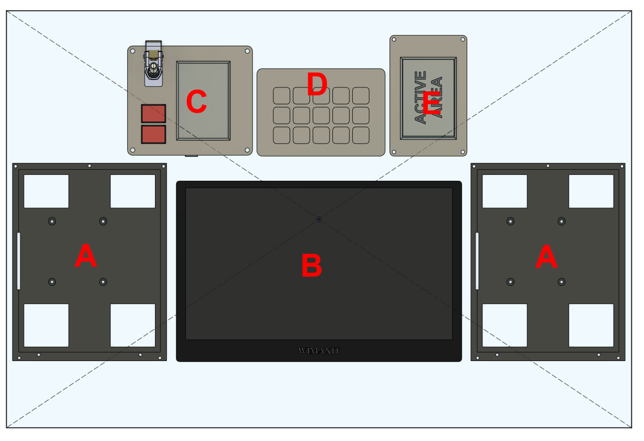
I'm looking at going for a generic panel I can use in conjunction with my Wathog HOTAS. Rough concept: null A - MFDs - custom HDMI TFT mounts with Thrustmaster Viper MFD buttons. These monitors are rectangular, so there's some extra space for indicators/gauges. B - MIP - 12-inch "portable" Multi-touch display. Main instrument panel (Helios) C - Landing gear panel - 3.5" TFT Uno shield. Multi-aircraft landing gear panel - Dispaly changes based on aircraft being flown. D - StreamDeck Various functions E - CWP - 3.5" TFT with built-in ESP32 Programmed as a multi-aircraft CWP. Layout, etc. changes based on aircraft being flown.
-
Have you made sure there's no clash in RS485 addresses? Try it without the Mega connected - IIRC there are/were some issues with Megas as RS485 slave devices.
-
Found this U8G2 full example: The font isn't quite as big as the GFX one I was using, but it works
-
Well I have a Hornet UFC font displaying almost full height using the Adafruit GFX library on a 128x32 OLED, but it won't display more than 4 characters, and it won't shift to the right far enough to add the ":" without clipping. I can't try U8G2 as there is apparently no way to convert a font for it if you don't have a 32-bit OS PC...
-
I've been trying to get a converted TTF font to run through the Adafruit GFX / 1306 libraries, but I've come to the conclusion the Nano isn't the Arduino for the job. I'll try a Mega...
-
Annoyingly, the font converter bdfconv won't run on my 64-bit Win 11 machine.
-
Maybe edit the font to be bigger? Where did the font come from?
-
IIRC, you tell it which font to use, and that includes the size.
-
DCS-BIOS: A-10C II Master caution LEDs not working anymore
No1sonuk replied to Griffon26's topic in Home Cockpits
Could you post your code, please, as well as what's not working - Preferably in a whole new post to keep it neat. Thanks. -
This guy laser engraves self-painted painted panels: https://thewarthogproject.com/the-panel-design This one uses mechanical router engraving, but with pre-made coated plastic: You could use the painting scheme of the first link with the engraving of the second. And most people use acrylic. IIRC, "Opal" acrylic works well to give good light transmission, but also reasonable "whiteness" when no light is on.
-
That would be the case if they're rolling digits, as the cockpit models use argument-based animation to move the wheels.
-
You might need to temporarily replace the font file in the Adafruit GFX library files, compile the code, then change it back. IIRC, it's the glcdfont.c file in the "Documents\Arduino\libraries\Adafruit_GFX_Library" folder.
-
Need Help with DCS Bios and Arduino Leonardo
No1sonuk replied to Archangel44's topic in Home Cockpits
This might be what you need: -
You might find this of use. -- Vertical Speed Indicator AVU-53/A Variometer = CreateGauge() Variometer.arg_number = 225 Variometer.input = {-6000.0, -4000.0, -3000.0, -2000.0, -1000.0, -500.0, 0.0, 500.0, 1000.0, 2000.0, 3000.0, 4000.0, 6000.0} Variometer.output = { -1.0, -0.83, -0.73, -0.605, -0.40, -0.22, 0.0, 0.22, 0.40, 0.605, 0.73, 0.83, 1.0} Variometer.controller = controllers.Variometer This is how the game maps the VSI values to the cockpit model needle positions. Output -1 is needle fully anticlockwise, +1 is fully clockwise. Just 13 mapping points. This information, along with other non-linear gauge mapping info, comes from the "mainpanel_init.lua" file in the module's "cockpit/scripts" folder.
-
Interesting. The hardware configuration part is good too.
-
Interesting. I'll need to check that out. My comment is from a hardware electronics engineer's point of view.
-
You're generally better off putting the LED resistors on the 7+1 segments side, rather than the 4 common lines. This is because the current will vary depending on how many segments you're running, meaning the one resistor may be too big for an "8", but too small for a "1". e.g.
-
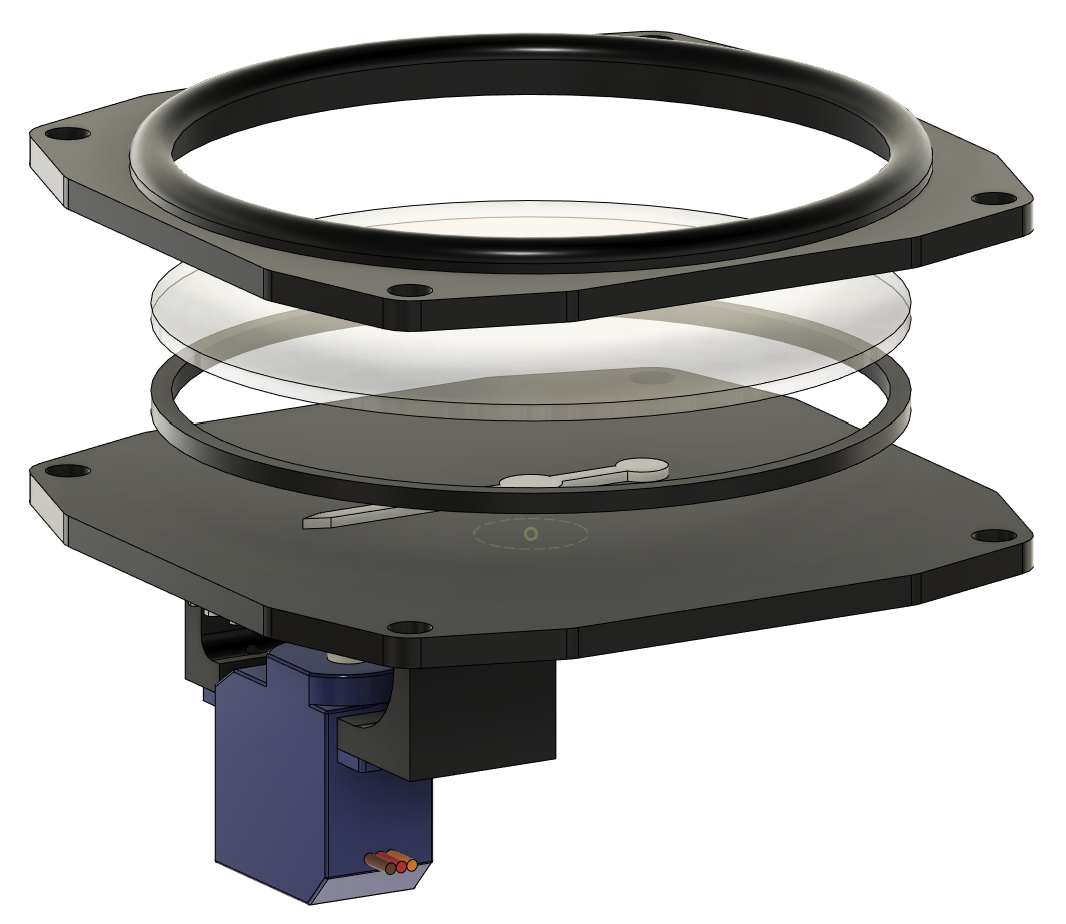
Might be worth trying helical gears on the servo unit if you can. I also add a ring to go into the faces behind the glass to retain it. null
-
I just confirmed this sketch causes the CMSP DISP switch to move on both A-10C modules in cold/dark condition - So just the switch moves. Test Arduino is clone Uno with ON-OFF-ON switch. Sketch used is exactly as above - no edits. Latest DCS update. EDIT: Also works on Mega. There must be something wrong with your setup.
-
Even if there is another switch that needs to be on for the CMSP switches to alter the function and displays, the "physical" switches in the cockpit model should still move with your DCS-BIOS connected switches.
-
Just tried it. Viper, Falcon and Lawn Dart...