No1sonuk
-
Posts
1601 -
Joined
-
Last visited
Content Type
Profiles
Forums
Events
Everything posted by No1sonuk
-
You'll have to use the ON-OFF-(ON) type for it to work. DCS interprets the "OFF" position as the centre. Have you tried using the CMSP switches to run another 3-position function you know works? e.g. Landing/Taxi lights or Master Arm switches?
-
You can add capacitors to what you have.
-
They don't have the capacitors.
-
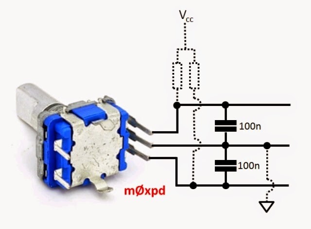
Do you have capacitors on the signal lines? It might help. See attached (the dotted resistors are not required).

-
Need help exporting the magnetic heading using DCS-Bios
No1sonuk replied to Bacab's topic in Home Cockpits
OK guys, the DCS-BIOS coders have solved the stability problem. The latest nightly build of DCS-BIOS (DCS-BIOS Nightly 2024-06-02) has the magnetic heading available in the CommonData section. https://github.com/DCS-Skunkworks/dcs-bios/releases It's an integer in degrees (0-359) which means no leading zeros. Because it's in the CommonData, it's available with all modules. -
To clarify: Put this at the top of your code: typedef DcsBios::RotaryEncoderT<POLL_EVERY_TIME, DcsBios::TWO_STEPS_PER_DETENT> TwoStepRotaryEncoder; // A custom rotary encoder with two quadrature steps per physical detent. Then use "TwoStepRotaryEncoder" in place of the "DcsBios::RotaryEncoder" part of the code lines. e,g, TwoStepRotaryEncoder ilsKhz("ILS_KHZ", "DEC", "INC", PIN_A, PIN_B);
-
Have you tried updating DCS-BIOS? DCS updates sometimes break the DCS-BIOS controls until it's updated.
-
KA-50 Targeting Mode Control Panel - Head-on airborne target button issue
No1sonuk replied to Jocman's topic in Home Cockpits
Isn't it just : tryToSendDcsBiosMessage("WEAPONS_FORWARD_HEMI_TARGET_BTN", "1"); Because it's the bottom line function, not the control class which "DcsBios::" defines. -
Arduino Error Code for DCS Bios A10 CMSP Display Sketch
No1sonuk replied to Kenpilot's topic in Home Cockpits
Would need to remember to remove the same characters from the second line string as well. -
Arduino Error Code for DCS Bios A10 CMSP Display Sketch
No1sonuk replied to Kenpilot's topic in Home Cockpits
Pretty sure the labels are 4 characters separated by a space, meaning a 20x2 is needed. -
Need help exporting the magnetic heading using DCS-Bios
No1sonuk replied to Bacab's topic in Home Cockpits
TBF, I didn't go looking for any other parameters. The physical gauges use those "argument numbers" as part of the cockpit animation. DCS giving the heading argument a value from 0 to 1 sets the rotation angle of the compass ball. DCS-BIOS translates 0 to 1 into 0 to 65535 to make small steps easier. Something that might be worth considering is to get the true heading from the common data and compare it to the standby compass at the beginning to get the variation, then apply that to the true data from there to get a stable reading. -
Need help exporting the magnetic heading using DCS-Bios
No1sonuk replied to Bacab's topic in Home Cockpits
I've got a test output of the F-16 Standby compass heading working. I'm not sure how it will get into the main DCS-BIOS, though. One thing to note is that it's the actual "floating ball" data, so it lags and wobbles about a bit. I'm not sure if that's what you want, but I think it's all there is available. -
Need help exporting the magnetic heading using DCS-Bios
No1sonuk replied to Bacab's topic in Home Cockpits
Usually, if there's a gauge on the panel, the data is available in DCS-BIOS. I just submitted an "issue" on the DCS-BIOS Github. https://github.com/DCS-Skunkworks/dcs-bios/issues/671 -
Need help exporting the magnetic heading using DCS-Bios
No1sonuk replied to Bacab's topic in Home Cockpits
Maybe use the true heading and add the variation manually? Not sure, but I think it's available from the briefing screen. -
Google Translate: Other options I've seen are silicone sealant and furniture repair wax. I like the idea of using a pre-made box with a 3d-printed front.
-
Each of the DCS-BIOS related sections has an "issues" tab. This one is specific to BORT: https://github.com/DCS-Skunkworks/Bort/issues
-
Do you have 1 LED per "segment"? Generally speaking, a LOWER resistance would increase the current. There's an interesting idea in post #6 here - use a pot to make it adjustable: https://forum.arduino.cc/t/question-about-the-correct-resistor-for-max7219-rset/228971/7
-
I'm not seeing the reports you mention. It IS active, but don't forget time zones. e.g. I think the main dev is in Finland - 2 hours ahead of London time, 7 ahead of the US East coast...
-
I've flagged this thread in the Skunkworks Discord. If you have a Github account, you can also create an "issue" there.
-
T 16000 M FCS Hotas --- Can I move the throttle more smoothly?
No1sonuk replied to loscsaba86's topic in Thrustmaster
My T16000 set had a stick twist failure while it was still in warranty. TM didn't offer repair, just return/refund, so I reversed the mod and returned the set. I went to Warthog HOTAS. Though I still miss the T16000 for Elite Dangerous. -
There have been some issues with a Mega as a slave, and yours might be wired incorrectly anyway. I think you need to use TX0 and RX0 if you're using the Mega as a slave. You use TX1 and RX1 for the RS485 network on the master because TX0 and RX0 are used for the USB comms. All the other Arduinos are disconnected from the USB, so TX0 and RX0 are used on those.
-
T 16000 M FCS Hotas --- Can I move the throttle more smoothly?
No1sonuk replied to loscsaba86's topic in Thrustmaster
There's a linear bearing upgrade you could try if you have access to a 3D printer: https://www.thingiverse.com/thing:4748193 -
Pretty sure it won't work with Hub. It's years out of date. You'll need to switch to the DCS-Skunkworks Fork (formerly called the Flightpanels Fork).
-
There's always the Arduino Pro Micro...
-
There's a "control reference" section of the DCS-BIOS files.