No1sonuk
-
Posts
1601 -
Joined
-
Last visited
Content Type
Profiles
Forums
Events
Everything posted by No1sonuk
-
Sorry I've just seen this - you've posted it in the wrong forum. It should be in the main Home Cockpits section, not the 3D printing sub-forum. As for the question: If one 3-position switch works, there must be something wrong other than the code. Which version of DCS-BIOS are you running?
-
Which Bodnar board?
-
You should start a fresh post in the forum rather than post for help in a "Working code" thread...
-
Thanks, But I should note the addresses you have in these sketches don't work in my up-to-date Open Beta / Flightpanels DCS-BIOS install. They all need 0x0010 to be added to them. A named address file was added to DCS-BIOS a several months ago to make updates easier.
-
using six switches to control 8 inputs - can it be done?
No1sonuk replied to lesthegrngo's topic in Home Cockpits
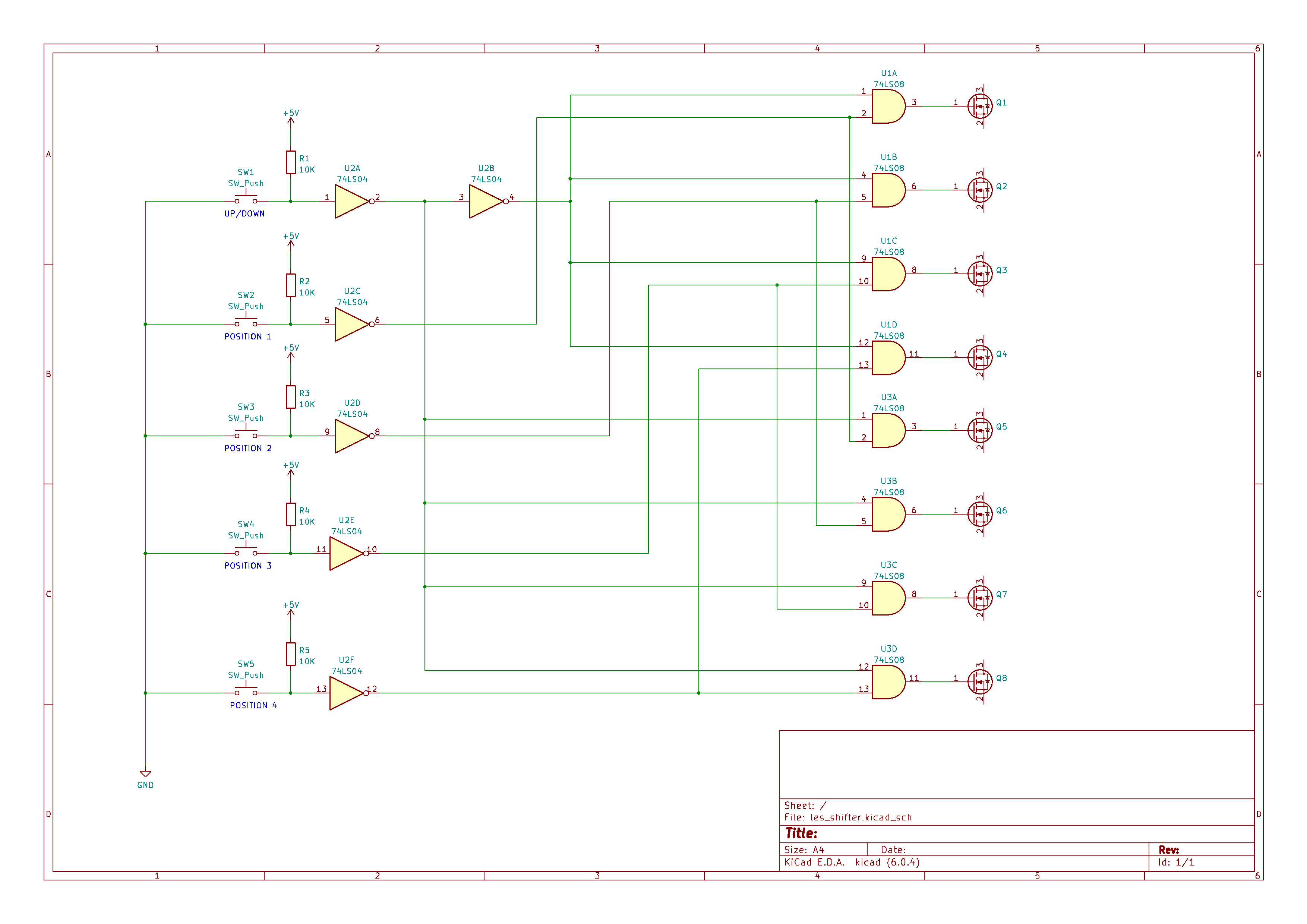
That's easy. Duplicate the top switch and resistor. Connect the new switch to the input of U2b instead of the output from U2a. -
using six switches to control 8 inputs - can it be done?
No1sonuk replied to lesthegrngo's topic in Home Cockpits
This is what I mean about the hardware if/then: U1 and U3 are quad 2-input AND gates (74xx08). Power pins not shown. U2 is a hex inverter (74xx04 or 74xx14). Power pins not shown. Q1-8 are whatever will switch the Bodnar board inputs from a 5V active-high logic level. That may require additional circuitry. Theoretically, with the up/down switch open, the 4 position switches should fire the outputs only on U1, and with up/down closed, they should only fire the U3 outputs. There's nothing stopping more than one output firing if more than one input switch is closed.
-
using six switches to control 8 inputs - can it be done?
No1sonuk replied to lesthegrngo's topic in Home Cockpits
You could use relays to change over between top and bottom with the top/bottom switch controlling the relay coils. MOSFET switching might work. It'd be easier with a couple of logic chips as well, to do the "if/then" job in hardware. -
The point is that the Arduino doesn't HAVE TO support any number of LEDs. The 5V supply for the LEDs comes from the USB before it gets to the Arduino. The Arduino then turns on and off a MOSFET switch that turns the LEDs on and off. The only problems with this are: 1) Tapping the USB power supply. 2) The USB source being able to drive the current - Ideally this should be a powered hub. A better alternative, if you can do it, is to use 12V and a series-parallel circuit. In this case, you have multiple chains of 3 LEDs in series with a resistor. Have a look here: https://rudysarduinoprojects.wordpress.com/2019/01/13/fun-with-arduino-05-connect-multiple-leds-with-a-relay-or-a-fet/
-
My guess would be that the LED power comes direct from the USB, and the PWM brightness control uses a MOSFET.
-
Where are the lights you're referrring to?
-
Yes to layers. Not sure about the other stuff. And if you have photoshop, you might be able to do it in that too. I just suggested Inkscape because I know it can do it. All you need is to be able to import the vector graphics and keep the real size information intact.
-
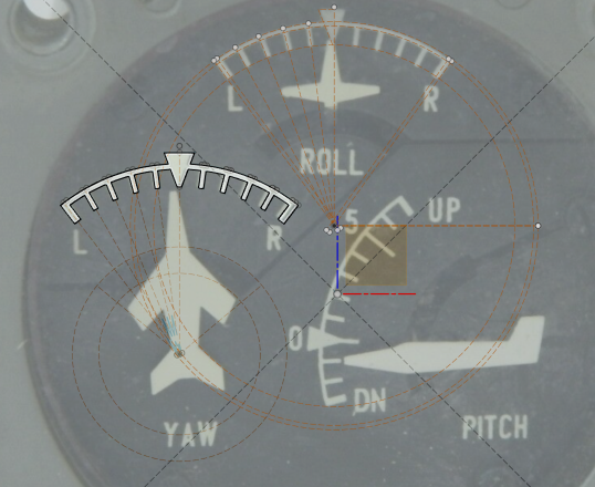
The simple answer is you can't do everything you want in Fusion 360. I'll go through each part of your question one by one: Line thickness You can't do line thickness in F360. For a given line thickness and length, you'll have to draw a rectangle of appropriate size. Curved lines are harder, but possible. Line colour Not possible in F360 as far as I'm aware, unless you model it as a solid, then change its appearance. Circles See this screenshot: Both circles are 50mm diameter, but each was drawn slightly differently. The top one was drawn by clicking the centre point, then move the cursor out a bit. You'll notice the diameter is highlighted. At this point, type the diameter wanted and hit enter. The circle will resize and you'll get the dimension inside it as shown in the top. The bottom one was drawn by clicking the centre point, then move the cursor out until the dimesnion gets to 50mm, then left click. To add the dimension to the bottom one, click on the dimension tool (A). Then click on the line of the circle (B) and move the cursor inside the circle a bit. The dimension will now appear. Left click to set the position, then press Enter to fix the dimension. The circle will now have the dimension in it, like the top one. The dimensions can be moved by click/drag or changed by double-clicking on the numbers. Construction lines Here's where it gets easy... You can do this in at least 2 ways: 1) Draw the line. Select it, and click on construction line in line type (C). 2) Change the line type, then draw your line(s). Circular patterns There's a circular patterns tool in the Create menu. The bottom line(s) Fusion 360 isn't really the best option for drawing complete gauge faces unless you intend to 3D print or engrave them. A vector drawing package like Inkscape (free) is better, and it can do all the line thickness and colour things you want. HOWEVER, F360 can help to make the gauge face fit your model by creating the template in F360, export as DXF, then finish it in Inkscape, etc. I do this with PCBs so they'll fit in the model. Here's an example I'm working on (a Tornado trim indicator). The Yaw scale is done, and I've started the layout for the Roll one. Hope that is of some use to you.
-
DCS has updated too far for Hub to cope anymore. You'll need to update, I'm afraid.
-
Sorry if there's a "ghost notification". I wrote a long post with text and graphics that only posted the graphics and lost the text. It's after 3am, so I'll redo it after I get some sleep.
-
You can change the name immediately before the parenthesis to break the conflict. And which version of DCS-BIOS are you using?
-
IIRC, the multi com port file does multiple calls of the single version.
-
Yes. You can use ActionButton. ActionButton only triggers on the press action, not the release. For that particular button (Station Jettison Select Centre): DcsBios::ActionButton sjCtr("SJ_CTR", "TOGGLE", PIN); "SJ_CTR" is the switch function. "TOGGLE" is what you want it to do when triggered. PIN is the input pin number.
-
transparent components like the landing gear knob
No1sonuk replied to Bucic's topic in 3D Printing for DCS
I made mine in two halves and used low-density concentric infill. I'll grab a photo in the morning. -
I PMed the invite link - not sure if I should put it here.
-
Map Button to specific USB Port ( Fan in Mi8/mi24)
No1sonuk replied to Watari's topic in Home Cockpits
If the fan is mapped in DCS-BIOS, you could use an arduino to turn on the physical fan. -
The Fork isn't "new,new" it's at least a few years old, and the Skunkworks name is a recent change. It used to be called "Flightpanels Fork". The name was changed because it had diversified from just creating an interface for Saitek Flight Panels to cover Stream Decks, Arduinos, and more recently, there's some work going on WRT WiFi-connected ESP32s.
-
It's now here: HOWEVER, the original "Hub" version of DCS-BIOS is no longer supported. The Skunkworks Fork (Formerly called "Flight Panels Fork") is regularly updated and maintained. https://github.com/DCS-Skunkworks There's a setup guide here:
-
How many ways do you need, and what sort of space constraints? You could possibly build a rotary switch with microswitches around a moving column, with a button under the column.
-
The inference with talking about hollow-axle steppers is to pass the wires without using slip rings.
-
If the wires are fixed at the ends, like wires usually are, they WILL twist as the gimbal turns. If it turns one way more than the others, the wires can't untwist.