.png.106163b2ff8ba3c8a044143ab5fd143e.png)
winghunter
-
Posts
738 -
Joined
-
Last visited
Content Type
Profiles
Forums
Events
Everything posted by winghunter
-
I've made this panel in 10 minutes using only a black & white printer. I simply scaled to 5.75" and printed the texturemaps from this F14 mod: https://www.digitalcombatsimulator.com/de/files/3313661/ The photoshop file is here if you want to give it a go. Then I glued this to 5mm foamboard. Then used a center punch to make small holes just big enough to screw in the switches. It's surprisingly sturdy, I can toggle the switches without any wiggle room. Haven't even needed hotglue. And it's ultra lightweight, I guess I could build this whole cockpit under 10 pounds. Which makes me think I will stick with this for a while as I can easily diassemble and stow this some place. I

-
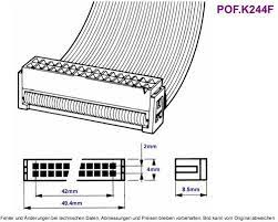
.thumb.png.d43db0aa51621a39a2161ec5c6fff372.png) Hmm, I wonder if similar ones exist without the data port. And if they would have a reasonable lifetime when driven directly by a 5V source. I.e. LED 5060 or these https://www.aliexpress.com/item/32816992410.html
Hmm, I wonder if similar ones exist without the data port. And if they would have a reasonable lifetime when driven directly by a 5V source. I.e. LED 5060 or these https://www.aliexpress.com/item/32816992410.html -
What about these LEDs ? They already have built in resistors and take 5V directly from power source. They are a bit more expensive but they already come in a matrix form ready to solder. https://de.aliexpress.com/item/1849928878.html https://www.amazon.de/CHINLY-stücke-WS2812B-Adressierbare-Kühlkörper/dp/B01N0GIHFG/ref=dp_prsubs_1?psc=1
-
I have used these cheap chinese USB cams for such projects before. The should be more than good enough for such a use case. Its not that this would need super high res, probably even 720p is enough. Considering you cant get more than 40cm distance behind a panel. That means the switches etc will be rather large in the image. https://german.alibaba.com/product-detail/conference-camera-for-pc-price-desktop-pc-web-cam-1080-full-hd-webcams-camaras-web-1080p-online-video-call-website-usb-camera-1600153547249.html?spm=a2700.galleryofferlist.normal_offer.d_title.547b21c8vo3lSZ https://german.alibaba.com/product-detail/professional-oem-usb-2-0-web-camera-1-7mm-fisheye-lens-mini-wide-angle-1080p-full-hd-industry-pc-uvc-micro-usb-camera-60812785995.html?spm=a2700.galleryofferlist.normal_offer.d_title.547b21c8vo3lSZ I.e. this is a 280p image, but already contains enough visual information to track many buttons. Remember the backside will be visually more simplistic.
-
Ok I didnt know that. So I agree this would make the whole setup too complicated. Onecould buy commercial LED panels but they would drive up the cost. I just need more than 32 inputs per board really, otherwise I have too many USB boards to deal with. So let me know when you release a 64 or 128 model. I would buy your 32 model for now just to try it out.
-
I really like this, because its a completely wireless and very user-friendly solution. And USB cameras for this usecase are even less expensive, around $5. Additionally people can completely create their own switches while with electronics this is much harder to do. I mean people could even make switches and knobs out of wood. Also great for kids to hook up their toys to the computer.
-
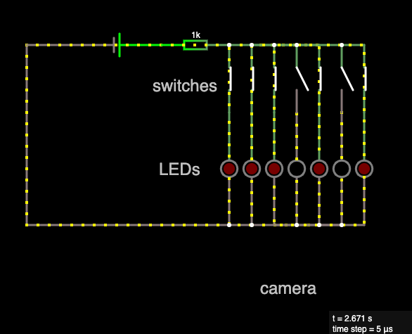
Before I add more confusion to the LED solution, here is a simple sketch of how I intended the wiring. As simple as possible, so everyone can wire this without needing a printed circuit board. And here is a link to a live circuit https://tinyurl.com/y2opwf9f
-
The idea is to connect one switch to one LED, just as you connect one switch to one Arduino input. I don't see how this would add more cables or even require a circuit board ? The optical transmission is not to bridge distance, but no remove the limitation on the number of inputs per USB device. I.e. a single usb device can now handle 100k inputs. If you can find the muse and space to solder 100k LEDs that is.
-
The idea of using QR codes on switches is growing on me. These could be 3D printed and reveal the QR code when pushed. The advantage is that you can place the switches anywhere you want without having to rewire or reconfigure anything. Also, the cameras can easily read QR codes and the setup would be even simpler than building an LED matrix. Of course this would require access to 3D printers but eventually these switches could be mass-manufactured in China
-
Well if you used ready made LED panels they could get expensive and they also often require a driver software. I thought about DIY LED panels using just a drilled board or 3D printed frame, where you stick in $0.001 LEDs. Then you would just leave enough space / empty LEDs for any module to be swapped without having to reconfigure 3 additional inputs.
-
This is great, i wish these had 64 inputs per board. Is it possible to connect flatband cables directly ?
-
I think this would just be a software problem. A) you could dedicate an entire different section of the LED matrix for each of your panels, as this is only limited by the amount of LEDs you can buy, LED's are inexpensive, costing as little as 0.001$ (RED) to 0.01$ (RGB) per piece B) You could define each panel by grouping LED's in the software. Then you could simply swap the keybindings for a certain panel. Of course you should also connect each panel via i.e. a flatband connector to the LED panel. So you can also easily swap elements on the hardware side.
-
I thought about this approach as well. I've already written CV applications but there are some limitations to this. First of all, your hands and head can obstruct the buttons, especially when you operate them. But also CV takes more processing power. EDIT: Re-read your post. Thats a great idea to have mechanical flags on the underside. But you would still need one camera per panel. So you will have to deal with multiple cameras. But therefore less wiring... Could be interesting
-
I love Arduinos, but I hate dealing with 10 units and keeping them up to date. LED's are inexpensive, costing as little as 0.001$ (RED) to 0.01$ (RGB) per piece https://www.alibaba.com/product-detail/5mm-LED-Diode-Dip-Light-Emitting_1600238959281.html You would only need a single power supply or even a battery can do the job. The amount of wiring needed is comparable to wiring the Arduinos so there is no advantage here. The only advantage would be that you don't have to deal with different software for each arduino. Ideally you wont have to write any software as you could simply use my clicky software with a GUI to assign buttons to keys. The software would be open source and MIT licensed, for everyone to use.
-
Than you have to make an interpreter for the LED-cluster image, which would need a standalone CPU-unit. Yes, though I have written similar software to interpret realtime camera footage, it's easier than it sounds. The CPU load is also fairly low on todays systems, a raspberry PI can perfectly do this task which is around the same price tag as an Arduino.
-
Its a dual cockpit with RIO so I need a lot. But also I want the flexibility to add more things later, make it modular swap modules etc. This would be much easier with this setup as its very simple. With this many inputs I can just swap entire sections without having to reprogram anything.
-
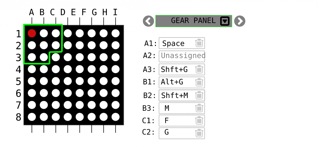
Hello I'm in the planning stage of a simpit and what I already don't like is the hard wiring of components and having to use multiple arduinos in different spots. I want the whole structure to be more modular as in being able to reassign and rewire buttons to different locations without having to build new software for the Arduinos. So thinking of alternatives, here's my concept. Theory Can you think of a common computer input device that is capable of reading 1 million inputs 60 times a second ? Yes, an HD USB camera. These are typically able to send 720*1080 pixels of uncompressed RGB @ 60fps to the computer. Now, for the camera to read our inputs we have to connect each switch directly to an LED, and position these LEDs in a grid. We could also simply buy a ready made LED matrix. That means in theory we could now read 1 million inputs per second, but in reality we probably need some spacing between camera pixels to increase resilience. Hence, if we leave 9 pixels around each input pixel we could still read 100000 inputs @60 times a second. Mapping To match each pixel to a control input is fairly easy, this can be done in a raspberry PI or as a program running on your computer. Multi-stage switches can be mapped to a single LED using 200ø resistors in series, therefore controlling the LED intensity in multiple steps- Potentiometers can be wired to an RGB LED controlling a color shift from red to blue or green which can be detected by the camera. For example we could build the last 2 lines with RGP LEDs which can be wired to potentiometer inputs. I.e. LED 1,1 -> button 1 ( RED LED ) LED 2,1 -> button 2 ( RED LED ) LED 4,1 -> multi-stage rotation switch ( RED intensity ) LED 1,40 -> potentiometer input EDIT: On the software side you could group LEDs into "panels" and assign key combinations Pros & Cons The nice thing about having this LED matrix is that it works STANDALONE - without a computer, chip or software. It's just pure electronics and allows you to debug the system visually. The matrix would need to be enclosed in a box to not affect the camera with other light sources. You also don't need ANY programming skills. You could simply use my software and assign each pixel to a button with a point & click interface. The other nice thing is that this is not limited to DCS. Your hardware can work with any other flight sim, while the software emulates keystrokes and keeps your mappings. Now, to wire up 100s buttons to LEDs is certainly no easy feat. But im wondering if it's really harder than wiring up 100s of switches to arduinos - and writing custom software for each in DCS bios. Also dealing with and updating multiple arduinos is not very maintainable. A disadvantage would be that our input rate is now limited to 60 fps. So this input method may work well for switches or potis. But maybe it's not fast enough for your HOT firing trigger. Yet, i can only think of the firing trigger that requires really fast millisecond response times, any other input in my plane is totally fine at 60fps. Another disadvantage may be that we loose some accuracy with potentiometers. Due to converting them to RGP light and reading it through a camera. For things like flaps this may not be an issue, but if you use a poti to move a cursor on a map this could be more twitchy. Skipping the LED step An optimisation would be to skip the LED step entirely. How is a $30 USB camera able to serialise this much data and send it to the computer in a manageable format ? If we can somehow connect directly to the camera's serialiser we can save some work and gain more precision. Any thoughts?
-
Where can we download the dcs or 3d files for your panels ? Thanks