Search the Community
Showing results for tags 'usb'.
Found 5 results
-
Hey guys, After some time the analog pots of my very nice Thrustmaster Cougar started putting out erratic values and were spiking all over the place. These pots seem really cheap and even if there were still replacement parts from TM available, in my eyes it would not make much sense to replace them with the same low quality parts. I have been tinkering with my idea of contactless sensors for the Cougar now for around a year and I think I am finally satisfied with what I got. These sensors are plug and play, fully sealed, make use of a ball bearing on the axle and use a N52 neodymium magnet for contactless angular measurement. The PCBs are only 14 x 20 mm (0.55 x 0.78 in) and were quite the hassle to make all the necessary ICs and SMD parts fit in. The housing is a two part SLS 3D print from Shapeways, which is a very tough material. I use it for all sorts of mechanical parts. (Here you can find development pictures: http://simhq.com/forum/ubbthreads.ph...er#Post4419858) These sensors in reality are not hall sensors, but instead use next gen magnetoresistive sensors which are heavily used in the automotive industry and have basically replaced hall sensors there. The main advantages are higher sensitivity and actual angular measurement instead of only measuring the magnetic flux (as hall sensors do). The same type of sensor is used eg in Baur BRD devices in form of MagRez or RAMS. These devices are known for their amazing precision and I wanted to make use of the same sensor in the Cougar. Installation is as easy as stick it in, screw it tight, plug it in and done. You can calibrate them as you normally would via the Hotas Cougar Control Panel and the whole thing stays fully TARGET compatible as well. Now enough talk, here are some pictures. TM Cougar stick sensors Because the question comes up a lot, you can invert every axis of the Cougar in the first tab of the Cougar Control Panel (CCP) software. If you are interested or want to ask questions please contact mtwsims@tutamail.com. No PMs please! Please note that sometimes I am rather slow to respond and it can take me several days to answer your emails. Payment via PayPal or SEPA bank transaction, but for PayPal I would have to add the PayPal fees on top. All sensors are designed, assembled & hand soldered by me. Every single sensor is then checked and calibrated manually. I can proudly say it is 100% Made in Germany. Price: 44€ (set of two sensors) + 7€ tracked international shipping (from experience shipping within Europe is around 2-6 days and to the US 14 days) -------------------------------------------------------------------------- TM Cougar Throttle standalone USB adapter + digital contacless 14 Bit GMR sensor I also have made a USB standalone adapter for the Cougar with a high res 14 Bit GMR TLE5011 digital sensor on the Throttle axis. This one is similar to the TUSBA, but half the price and with an added extension bay that supports extra shift registers, encoders, buttons, analog and digital axis. You can buy the USB standalone adapter without the new digital sensor and simply keep using the original pot. However you can not use the digital sensor without the USB adapter, as it communicates via the digital SPI protocol. I have been selling these on the german Craigslist/ ebay since 2018 and people were really enthusiastic about their performance. Price is 33€ for the adapter and 20€ for the sensor + 7€ tracked international shipping (shipping is only paid once per order) -------------------------------------------------------------------------- TM Cougar Throttle hall sensor kit I can now also offer a simpler Hall effect sensor kit for the Throttle. It consists of an Allegro 1324 hall sensor + cable and a 3D printed casing + N52 magnet. It is plug and play for the Throttle unit without my USB standalone adapter and similiar to older hall sensor kits for the Cougar. The difference is it requires no fancy mounts and is fixed in the correct position in two out of three axis for more precision. The third axis is dependent on magnet strength and can be hardware and or software calibrated. By hardware calibration I mean depth of insertion into the 3D printed case, nothing to it really. The mod is only compatible with the 5V mainboard version as is! The solution to this problem is a little voltage conversion board that is 3€ extra. The 5V and 3.8V versions differ in a resistor on the VCC line. Here you can check which version of the Throttle mainboard you have: https://forums.eagle.ru/topic/135000-new-hall-sensor-kits/?do=findComment&comment=2916178 Awesome installation instructions by JCook: Price is 22€ + 7€ tracked international shipping (shipping is only paid once per order) -------------------------------------------------------------------------- Cougar Ministick/ Slew replacement This mod replaces the original Ministick of the Cougar Throttle. Often times the original Ministick is worn out and as no replacement parts are available from Thrusmaster anymore a solution was in dire need for many HOTAS Cougar fans. The thumbhat is modeled after the earlier block original F-16 slew. The mod is completely plug and play. Price is 22€ + 7€ tracked international shipping (shipping is only paid once per order) -------------------------------------------------------------------------- Cougar ANT sensor replacement This mod replaces the original ANT pot of the Cougar Throttle. Often times the original ANT pot is worn out and as no replacement parts are available from Thrusmaster anymore a solution was in dire need for many HOTAS Cougar fans. The implemented chip allows me to program the min/ max voltage output of the sensor to correspond to the exact min/ max angle actually needed in practice. For the Cougar ANT pot this means 270° of rotation in total. Important installation instruction: Price is 22€ + 7€ tracked international shipping (shipping is only paid once per order) -------------------------------------------------------------------------- CH Pro Throttle, CH Fighterstick, CH Combatstick, CH Pro Pedals etc. magnetoresistive sensors The cool thing about these MR sensors is that they are a drop in replacement for the standard CH pots, but contrary to these they work contactlessly. That means you can simply connect these sensors to your CH mainboard and done. You will never have to worry about deteriorating or dirty pots again. The CH Control Manager recognizes this sensor normally and you can calibrate it within the software. Important installation instruction: Price is 22€ + 7€ tracked international shipping (shipping is only paid once per order) -------------------------------------------------------------------------- 24 Bit shift registers for Cougar USB standalone, Thrustmaster gear, MMJoy2 These are compatible to the Thrustmaster hardware, to MMJoy2 and to my Cougar USB standalone adapter. The dimensions are 20 mm x 50 mm (0.79 in x 1.97 in), so they are very small and fit basically in everywhere. The pins are spaced in standard 2,54 mm (0.1 in) to fit normal header pins (see picture 2). I offer them either with or without header pins. The shift register is 24 Bit, so it has 24 inputs that you can connect buttons to. It can also be daisy chained, so you can put several shift register boards in series. Eg MMJoy2 supports 12 shift registers in series. So if you daisy chain 4 of my 24 Bit shift register boards, you have a total of 96 button inputs with just 2 pins used. If this isnt pretty damn cool I dont know what is. Price is 10€ + 7€ tracked international shipping (shipping is only paid once per order) If you are interested or want to ask questions please contact mtwsims@tutamail.com. No PMs please! Please note that sometimes I am rather slow to respond and it can take me several days to answer your emails. Payment via PayPal or SEPA bank transaction, but for PayPal I would have to add the fees on top. All sensors are designed, assembled & hand soldered by me. Every single sensor is then checked and calibrated manually. I can proudly say all my mods are 100% Made in Germany.
-
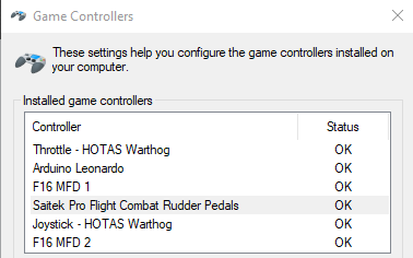
 The problem: When DCS is running all of my USB devices are recognized but least 2 do not respond. (Only with DCS running example Elite Dangerous works fine) If I unplug/plug(or rescan) the non responsive input is recognized but still no inputs are detected. (when taking the screenshots my rudder pedals, Arduino controller, and both of my MFD's did not work. The previous game launch with no physical changes it was my stick and 1 MFD. It never seems to repeat or have a common culprit. All USB inputs are detected and work correctly through windows game controller setting. They all worked for at least 6 months with no changes being made. As soon as I close DCS all inputs work correctly, if I open it again they stop working again. Nothing other than updates to windows and DCS when problem began(updated graphics drives tonight as a last ditch effort). The background: I have played this game since 2018 with the occasional issues that we have most all ran across. I have usually waited 2 weeks and searched the forums and found answers or the issues were automatically corrected from ED/Windows update etc. This problem has come about after not having the time to take to the skies for almost 2 months. No hardware or software changes have been made. I have checked that all USB drivers are updated, windows, DCS, video drivers are up to date and installed all windows optional drivers, thinking perhaps it was a windows problem over DCS until I tried Elite Dangerous with success. Any help to get this resolved would be greatly appreciated. I will provide answers as fast as I can, but please understand I am not always to my computer but will be as prompt as possible. I did not know of what files to attach as there is no error/crash etc. Thanks for any help, Prod
-
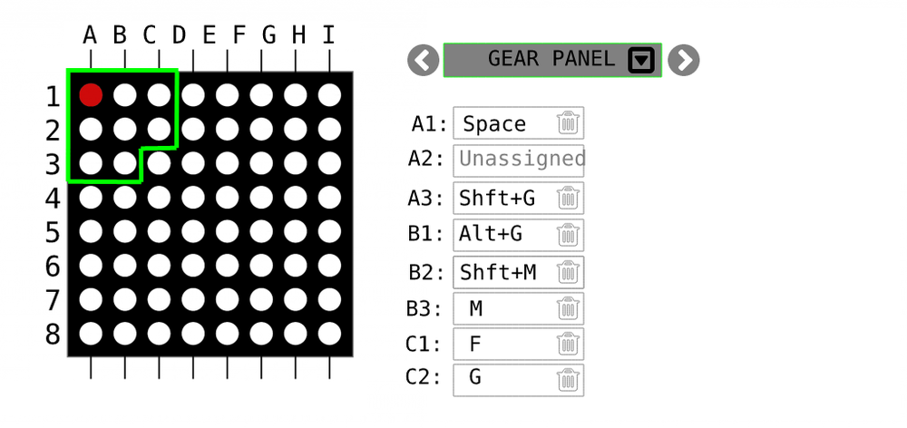
.thumb.png.d43db0aa51621a39a2161ec5c6fff372.png) Hello I'm in the planning stage of a simpit and what I already don't like is the hard wiring of components and having to use multiple arduinos in different spots. I want the whole structure to be more modular as in being able to reassign and rewire buttons to different locations without having to build new software for the Arduinos. So thinking of alternatives, here's my concept. Theory Can you think of a common computer input device that is capable of reading 1 million inputs 60 times a second ? Yes, an HD USB camera. These are typically able to send 720*1080 pixels of uncompressed RGB @ 60fps to the computer. Now, for the camera to read our inputs we have to connect each switch directly to an LED, and position these LEDs in a grid. We could also simply buy a ready made LED matrix. That means in theory we could now read 1 million inputs per second, but in reality we probably need some spacing between camera pixels to increase resilience. Hence, if we leave 9 pixels around each input pixel we could still read 100000 inputs @60 times a second. Mapping To match each pixel to a control input is fairly easy, this can be done in a raspberry PI or as a program running on your computer. Multi-stage switches can be mapped to a single LED using 200ø resistors in series, therefore controlling the LED intensity in multiple steps- Potentiometers can be wired to an RGB LED controlling a color shift from red to blue or green which can be detected by the camera. For example we could build the last 2 lines with RGP LEDs which can be wired to potentiometer inputs. I.e. LED 1,1 -> button 1 ( RED LED ) LED 2,1 -> button 2 ( RED LED ) LED 4,1 -> multi-stage rotation switch ( RED intensity ) LED 1,40 -> potentiometer input EDIT: On the software side you could group LEDs into "panels" and assign key combinations Pros & Cons The nice thing about having this LED matrix is that it works STANDALONE - without a computer, chip or software. It's just pure electronics and allows you to debug the system visually. The matrix would need to be enclosed in a box to not affect the camera with other light sources. You also don't need ANY programming skills. You could simply use my software and assign each pixel to a button with a point & click interface. The other nice thing is that this is not limited to DCS. Your hardware can work with any other flight sim, while the software emulates keystrokes and keeps your mappings. Now, to wire up 100s buttons to LEDs is certainly no easy feat. But im wondering if it's really harder than wiring up 100s of switches to arduinos - and writing custom software for each in DCS bios. Also dealing with and updating multiple arduinos is not very maintainable. A disadvantage would be that our input rate is now limited to 60 fps. So this input method may work well for switches or potis. But maybe it's not fast enough for your HOT firing trigger. Yet, i can only think of the firing trigger that requires really fast millisecond response times, any other input in my plane is totally fine at 60fps. Another disadvantage may be that we loose some accuracy with potentiometers. Due to converting them to RGP light and reading it through a camera. For things like flaps this may not be an issue, but if you use a poti to move a cursor on a map this could be more twitchy. Skipping the LED step An optimisation would be to skip the LED step entirely. How is a $30 USB camera able to serialise this much data and send it to the computer in a manageable format ? If we can somehow connect directly to the camera's serialiser we can save some work and gain more precision. Any thoughts?
Hello I'm in the planning stage of a simpit and what I already don't like is the hard wiring of components and having to use multiple arduinos in different spots. I want the whole structure to be more modular as in being able to reassign and rewire buttons to different locations without having to build new software for the Arduinos. So thinking of alternatives, here's my concept. Theory Can you think of a common computer input device that is capable of reading 1 million inputs 60 times a second ? Yes, an HD USB camera. These are typically able to send 720*1080 pixels of uncompressed RGB @ 60fps to the computer. Now, for the camera to read our inputs we have to connect each switch directly to an LED, and position these LEDs in a grid. We could also simply buy a ready made LED matrix. That means in theory we could now read 1 million inputs per second, but in reality we probably need some spacing between camera pixels to increase resilience. Hence, if we leave 9 pixels around each input pixel we could still read 100000 inputs @60 times a second. Mapping To match each pixel to a control input is fairly easy, this can be done in a raspberry PI or as a program running on your computer. Multi-stage switches can be mapped to a single LED using 200ø resistors in series, therefore controlling the LED intensity in multiple steps- Potentiometers can be wired to an RGB LED controlling a color shift from red to blue or green which can be detected by the camera. For example we could build the last 2 lines with RGP LEDs which can be wired to potentiometer inputs. I.e. LED 1,1 -> button 1 ( RED LED ) LED 2,1 -> button 2 ( RED LED ) LED 4,1 -> multi-stage rotation switch ( RED intensity ) LED 1,40 -> potentiometer input EDIT: On the software side you could group LEDs into "panels" and assign key combinations Pros & Cons The nice thing about having this LED matrix is that it works STANDALONE - without a computer, chip or software. It's just pure electronics and allows you to debug the system visually. The matrix would need to be enclosed in a box to not affect the camera with other light sources. You also don't need ANY programming skills. You could simply use my software and assign each pixel to a button with a point & click interface. The other nice thing is that this is not limited to DCS. Your hardware can work with any other flight sim, while the software emulates keystrokes and keeps your mappings. Now, to wire up 100s buttons to LEDs is certainly no easy feat. But im wondering if it's really harder than wiring up 100s of switches to arduinos - and writing custom software for each in DCS bios. Also dealing with and updating multiple arduinos is not very maintainable. A disadvantage would be that our input rate is now limited to 60 fps. So this input method may work well for switches or potis. But maybe it's not fast enough for your HOT firing trigger. Yet, i can only think of the firing trigger that requires really fast millisecond response times, any other input in my plane is totally fine at 60fps. Another disadvantage may be that we loose some accuracy with potentiometers. Due to converting them to RGP light and reading it through a camera. For things like flaps this may not be an issue, but if you use a poti to move a cursor on a map this could be more twitchy. Skipping the LED step An optimisation would be to skip the LED step entirely. How is a $30 USB camera able to serialise this much data and send it to the computer in a manageable format ? If we can somehow connect directly to the camera's serialiser we can save some work and gain more precision. Any thoughts?
-
 Hi All Currently I have an stuttering problem with my reverb g2 and (only) DCS, I "debug™" my problem and what I found is every time a USB device is connected to the PC the game stutters. In my very own case, I believe, the VR-cable have a broken cable for the HMD audio, triggering disconnection and re-connection of the audio device -> leading to an unplayable game. How to reproduce: Even without VR you can use any related USB device, like a controller or audio-device start a game and then physically disconnect the device, this will trigger the freezing. [see example vídeos] Example video in VR here: Expected behaviour: DCS not freezing every time a USB device is (dis/re-)connected?? I attach the log with the device (un)plug info correlated to the stutters 2021-12-05 09:17:11.445 INFO APP: Device unplugged: \\?\USB#VID_03F0&PID_1841#8&7392e18&0&3#{a5dcbf10-6530-11d2-901f-00c04fb951ed} 2021-12-05 09:17:24.554 INFO APP: Device plugged: \\?\USB#VID_03F0&PID_1841#8&7392e18&0&3#{a5dcbf10-6530-11d2-901f-00c04fb951ed} PLEASE ED-team, take a look on this issue it eventually will affect any random wired-vr user or wired-usb-(controller/audio) user dcs.log
 -
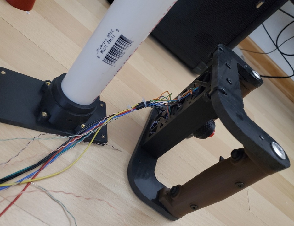
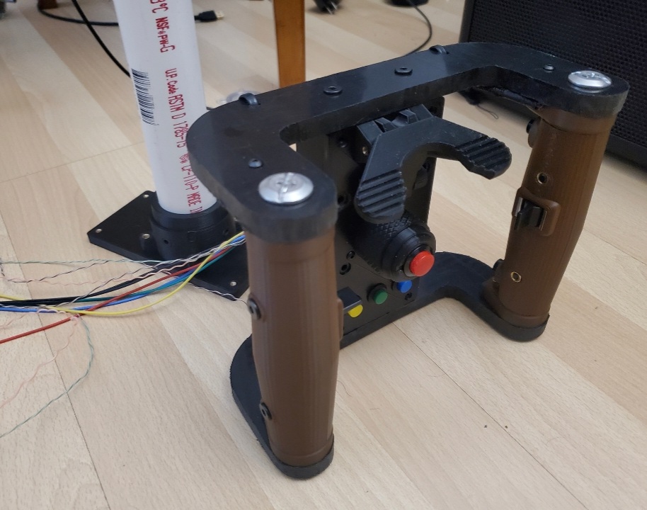
Been watching alot of videos on the M2 Browning Ma' Deuce, now inspired to make a wanna be controller, that will be functional for the UH-1H and Mi24P doorgun position. (hoping it will work for SA342 minigun variant and ch47 Chinook in future) **UPDATE** 07.26.2023 Eagle Dynamics added joystick binds to the Mi24P doorgun, so this build is working The minigun build is a blast to use, but agony to build. Trying to make this a fun project! ***NOTE**** if you plan to incorporate a bass shaker, you should add a relay to the trigger circuit, else any butt kicker out put will go to the shaker regardless if you are pulling the trigger our not, butt kicker wiring diagram TBA LINK TO STL FILES Spade Grip assembly https://www.thingiverse.com/thing:5863116 Top Gimbal Section https://www.thingiverse.com/thing:5927492 Gimbal Base Section https://www.thingiverse.com/thing:5932560 DCS Axis Controls and Button Assignments mappings: axis doorgun slew LEFT/RIGHT, axis doorgun slew UP/DOWN VR Re-center Fire Weapon Move Camera View Right Move Camera View Left Move Camera View Up, Move Camera View Down Move Camera View Forward Move Camera View Back Radio PTT List Parts (so far) : 2x M3-20mm screw (switch housing) 4x 1/4-20 x 3/4" bolt and nylock nut (mounting grips to c-bar) https://www.amazon.com/gp/product/B0BLKSYV3M/ref=ppx_yo_dt_b_asin_title_o04_s00?ie=UTF8&psc=1 1-1/4 in. x 2 ft. PVC DWV Sch. 40 Pip https://www.homedepot.com/p/Charlotte-Pipe-1-1-4-in-x-2-ft-PVC-DWV-Sch-40-Pipe-PVC-07100-0200/202018045 1x Cytron Arduino Pro Micro Compatible w/ Pre-soldered Headers (to be used with mmjoy2 to be programmed as windows controller) https://www.robotshop.com/products/cytron-arduino-pro-micro-compatible-w-pre-soldered-headers?srsltid=Ad5pg_FU8fbJVsHuWKCVgksU0nf4NqHeFxScMWDMW16LZgnUgTfwnzaJa0w if you do know how to program arduino use leo bodnar Bu0386 http://www.leobodnar.com/shop/index.php?main_page=product_info&cPath=94&products_id=204 or Leo Bodbar USB controller board http://www.leobodnar.com/shop/index.php?main_page=product_info&cPath=94&products_id=204 4x 6805-2RS Deep Groove Ball Bearings 25mm Inner Dia 37mm OD 7mm (for the potentiometer U-joint) https://www.amazon.com/gp/product/B082PYT33D/ref=ppx_yo_dt_b_search_asin_title?ie=UTF8&psc=1 12mm Momentary Push Button SPST https://www.amazon.com/gp/product/B07YDGVZ9B/ref=ppx_od_dt_b_asin_title_s00?ie=UTF8&psc=1 HDPE Sheet (to make the grip brackets..) https://www.ebay.com/itm/144548391463 2x paddle switches (to adjust the VR player view) https://www.ebay.com/itm/182340027352 1x limit switch (very snappy) https://www.ebay.com/itm/372481343091 Brown filament (to print grips) https://www.amazon.com/gp/aw/d/B0B2NZM21Z?ref=ppx_pt2_mob_b_prod_image brass inserts M3, M4, M5 (you will need a solder iron to install these) https://www.amazon.com/Hilitchi-Threaded-Embedment-Assortment-Projects/dp/B07VFZWWXY 13mm Momentary Push Button https://www.amazon.com/gp/product/B08B1P43XY 65mm bearing for gimble base https://www.amazon.com/dp/B082PWXCX9?psc=1&smid=A1THAZDOWP300U&ref_=chk_typ_quicklook_titleToDp Diodes (to eliminate ghosting inputs) https://www.amazon.com/Projects-1N914-Diode-General-Purpose/dp/B08MDGGCL5 STEP ONE (PREPARE GRIP ASSEMBLY) 1) print grips and grip covers 2) use a solder iron and mount brass threaded inserts ( M5 insert for the grip covers, M3 inserts for the grip tops) 3) print switch housing, then install the temco limit switch and connect the two halves of the switch housing together. use M3 x 20mm screw to keep the housing together 4) mount brass inserts M4 size for the switch housing 5) print Front panel and trigger lever. mount M3 insert to one side of the front panel where trigger lever will go 6) add compression spring (size 9.52 x 19.05) to trigger lever and screw down to the front panel 7) install 2x 1/4-20 nylock nuts to ends of the grips on the inside, for both grips. 8 mount grips on to the C-bar ***note: grips will have a through hole on the top- purpose to channel wires through. And there are two C-bars, with different size holes at the middle, pay attention when installing the grips, if incorrect, the housing will be upside down 9 install M5 nylock nuts inside the body frame. 10 Mount body frame to the c-bars with 4x M5 x20mm screws 11 solder 4x 12mm buttons with diode and wires. Also solder diode to toggle switches. Attach buttons and toggle switches to grip. 12 run wires through holes at top of the switch. And then channel wires through housing body. Leave slack / extra wire to later connect to gimbal 13 connect pvc pipe to housing back plate with M4 screws.