DummyCatz
-
Posts
191 -
Joined
-
Last visited
Content Type
Profiles
Forums
Events
Everything posted by DummyCatz
-

Missing function from the HUD for all Flankers!
DummyCatz replied to P1l0t's topic in Su-27 for DCS World
Related: -
investigating Hornet's Slow-State Energy Bleed?
DummyCatz replied to wilbur81's topic in DCS: F/A-18C
Hi, between 6:30-7:30 I saw some brief pulls but were quickly returned to normal AOA ranges before the roll begins, so maybe you were pulling too much? There was indeed an FCS issue reported by me about the high AOA rolling capability that might related to the issue you described (https://forum.dcs.world/topic/337280-missing-important-features-in-fcc-ofp-v107-lack-of-high-aoa-roll-and-yaw-performance-as-if-with-v1051), but is not quite the topic of bleed rate of this thread. -
investigating Hornet's Slow-State Energy Bleed?
DummyCatz replied to wilbur81's topic in DCS: F/A-18C
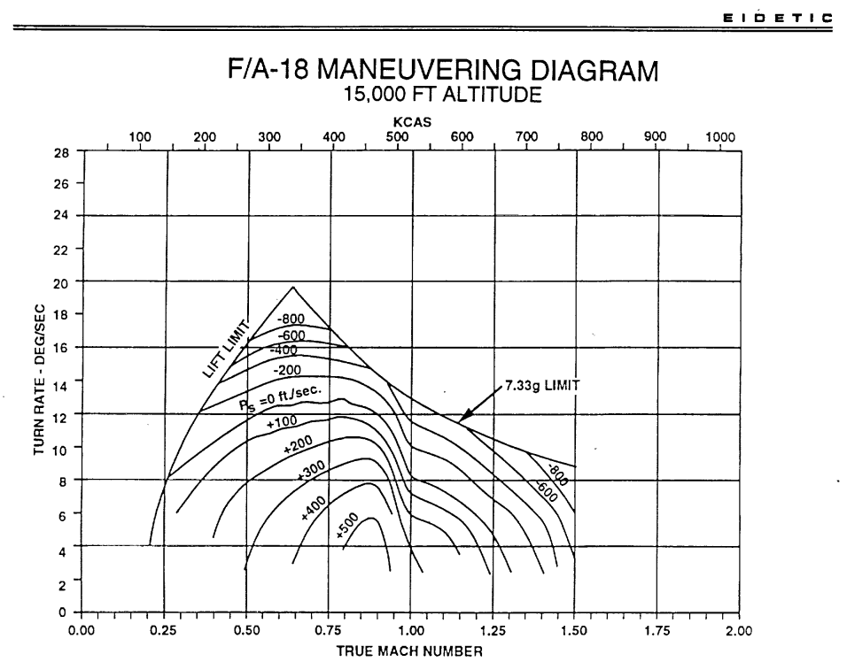
Thanks again @Figaro9 For the specific test that I conducted at M0.755 / 15000 ft, the eidetics EM chart (supposedly 33325lbs, 60% fuel, 402 engine, fighter escort loadout) indicates an SEP of -800 ft/s, while the SEP of a lighter and less powered F-18A (32366lbs, 60% fuel, 400 engine) is clearly beyond -1250 ft/s. (In DCS it's -417 ft/s) -
investigating Hornet's Slow-State Energy Bleed?
DummyCatz replied to wilbur81's topic in DCS: F/A-18C
Dear all, Please actually start reading the NASA paper and refer to the discussion above. I won’t be stating again how the EM diagram was used as an example and unrelated to HARV. Thanks. -
investigating Hornet's Slow-State Energy Bleed?
DummyCatz replied to wilbur81's topic in DCS: F/A-18C
Thanks @Figaro9 for the analysis. So we have a pretty high confidence that this EM diagram is related to our EPE aircraft. BTW our DCS hornet can reach M1.45 (overperforms) at 15000ft with the same loadout (33325lbs, 2a9,2a120) and 15°C mission temperature (standard atmosphere). I think the 1g envelope is worth investigating too. Ref page 84 of https://www.gao.gov/assets/nsiad-96-98.pdf -
investigating Hornet's Slow-State Energy Bleed?
DummyCatz replied to wilbur81's topic in DCS: F/A-18C
To continue my arguments, I'd like to point out the following: 1. As quoted from the paper, 'the chart following this illustrates the change in turn rate with loss in bleed rate and will serve to illustrate why CAMS is important'. There was no mentioning of such a diagram was generated from simulation or flight test data. 2. The inputs to the CAMS control law are sensor information, bleed rate (or Ps) level, and override commands from the cockpit. For an existing simulator, the only software job to do is to modify the control law. There's no need to generate an EM diagram in order for the control law to function. Bleed rate (or Ps) level is calculated in real time by using V-dot (or derivative of speed, dV/dt, as I did) and displayed on HUD. It is not taken from a diagram. Remember this is all about the modification of the existing control law. The underlying aerodynamic and thrust data can be whatever it is. That’s why you need to jump out of the whole HARV thing and start looking at the EM diagram itself, the g-limit, the max STR, the max level speed, all of them give hints. -
investigating Hornet's Slow-State Energy Bleed?
DummyCatz replied to wilbur81's topic in DCS: F/A-18C
As said the testing conditions are all speculations. BTW I forgot to mention that in my later testing of STR using the same config of GW=33325 lbs, 2 AIM-9 and 2 AIM-120, Fuel at 62%, the max STR is exactly at 13 deg/s, which matches the EM diagram. But tell me what kind of f-18 with 400 engine with the above config can reach a max level speed of M1.3 and above as indicated in the EM diagram? -
Hi, I'd like to keep this thread F-16 related, thanks.
-
investigating Hornet's Slow-State Energy Bleed?
DummyCatz replied to wilbur81's topic in DCS: F/A-18C
Thanks for your concern. The reasons why I suspect that the EM diagram is related to an EPE aircraft are: 1. The HARV validation flight were not yet started, and the paper is about all the plans of CAMS, in which the EM diagram alone was only used as an example. 2. According to previous speculations, the 7.33g limit is for an f-18 that weighs 33325 lbs, which probably have a fighter escort loadout with (2xa9, 2xa120) and 60% fuel. This coincides the figures from GAO report, that the max STR is as high as ~13 deg/s and the max level speed exceeds Mach 1.3. An f-18 with 400 engine is not able to achieve such performance. -
Would be nice if you could utilize the tester team and QA team to check the data points across speeds and altitudes with different loadouts in EM diagrams. I am only a single person so I can not do the QA job for you. I'm aware that flight model development is incredibly complex, and perfection is a tough target to hit. However, the community's confidence would be bolstered by a more detailed explanation of how these discrepancies arose and what steps might be taken to address them. Please take your time. Thanks.
-
investigating Hornet's Slow-State Energy Bleed?
DummyCatz replied to wilbur81's topic in DCS: F/A-18C
Apart from the said SEP issues, there're a few more things that require investigation in the provided trackfile: 1. G-limit is not consistent and dropped from 7.6g to less than 7g when bleeding speed from Mach 0.8 to corner speed. 2. The lift limit is at 34° AOA according to the NASA paper. The aircraft is supposed to reach the lift limit at corner speed. However in the trackfile, the aircraft is far from reaching the lift limit (34° AOA), even if it's passing the corner speed. -
investigating Hornet's Slow-State Energy Bleed?
DummyCatz replied to wilbur81's topic in DCS: F/A-18C
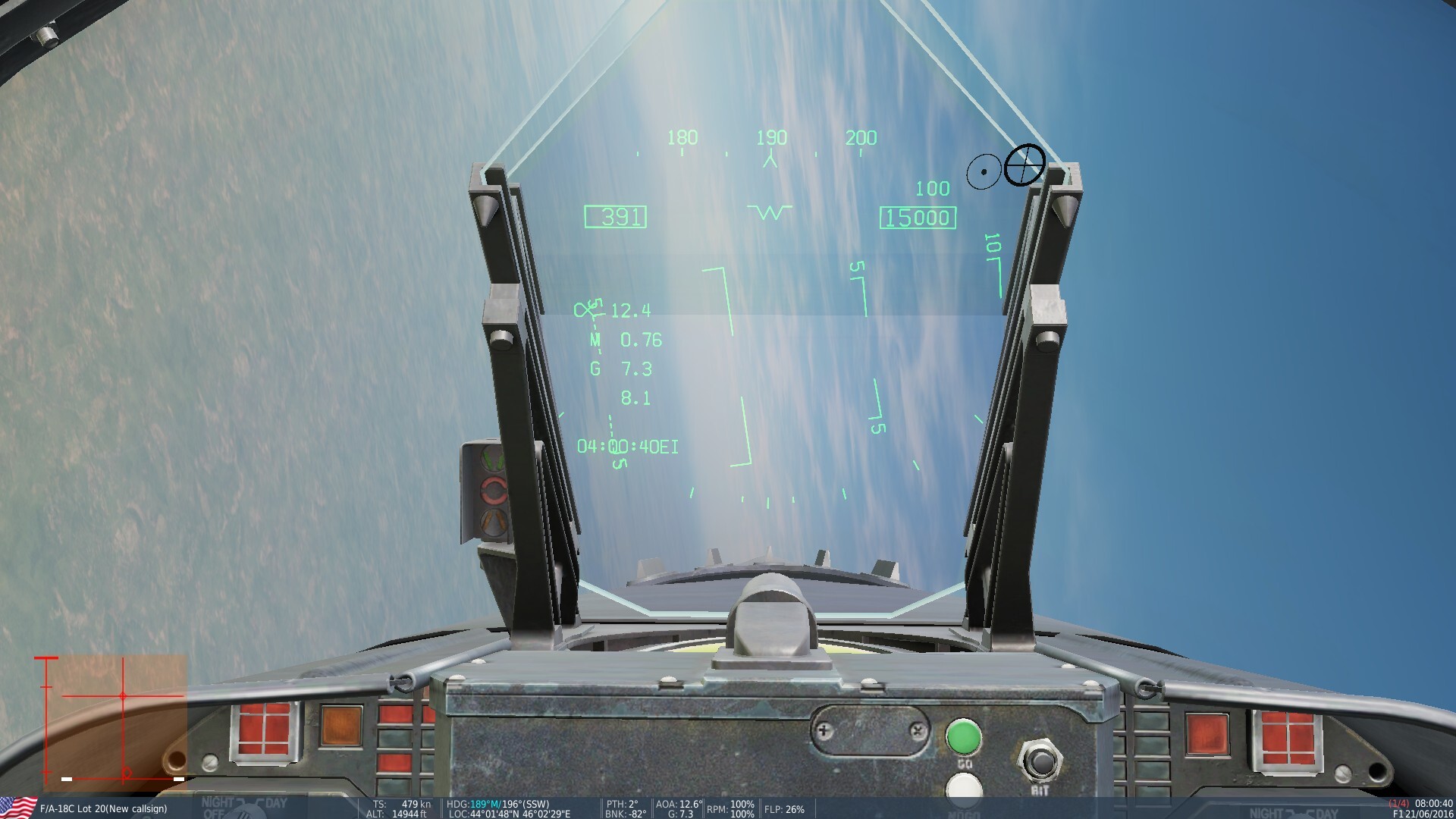
Now using the same testing technique from: https://forum.dcs.world/topic/356579-calculating-the-sep-specific-excess-power-of-an-instantaneous-turn I've completed testing the max performance instantaneous turn of the F-18 at 15000 ft, GW=33325 lbs, with 2 x AIM-9 and 2 x AIM-120. Fuel is at 62% for this GW. Sea level temperature is set to 15°C. I'm currently only interested in the SEP at Mach 0.75, to see if it's close to -800 ft/s during a max effort pull. Here's two images taken with 1 sec apart: SEP Calculation: 479 KTAS -> 469 KTAS in 1 sec: dh = +3 ft dV = -10 KTAS = -16.88 ft/s V = 474 KTAS = 800 ft/s (took the average) g = 32.174ft/s^2 dt = 1s The resulting Ps = 3 - 16.88 * 800 / 32.174 = -417 ft/s at the speed of 474 KTAS, or 0.755 Mach. So the energy bleed rate is way too low (Ps=-417 ft/s) compared to the EM diagram above (Ps=-800 ft/s). The aircraft overperforms in SEP. This result is a surprise, as the fighter escort loaded Hornet at 15000ft, 474KTAS bleeds even less speed than the very lightly loaded Viper at 10000ft, 473KTAS. F18 speed bleed test 15000ft.trk
-
I did not expect it to overperform in SEP at higher speeds too. But just as it's underperforming at lower speeds, which simply proves that the SEP values are totally not checked when ED was building their Flight Model. I'm done with the F-16. Now I'm going to see if the Hornet is overperforming in SEP. Will be posting in this thread:
-
investigating Hornet's Slow-State Energy Bleed?
DummyCatz replied to wilbur81's topic in DCS: F/A-18C
Yes, looks like this is the closest. https://dcs.silver.ru/Diagram/Fa18c @totmacher @TOT_53 I'll be basing my test on this config. So it seems to be a 402 engine considering the max STR is at 13 deg/s and at the same time, the max level speed exceeds Mach 1.3. -
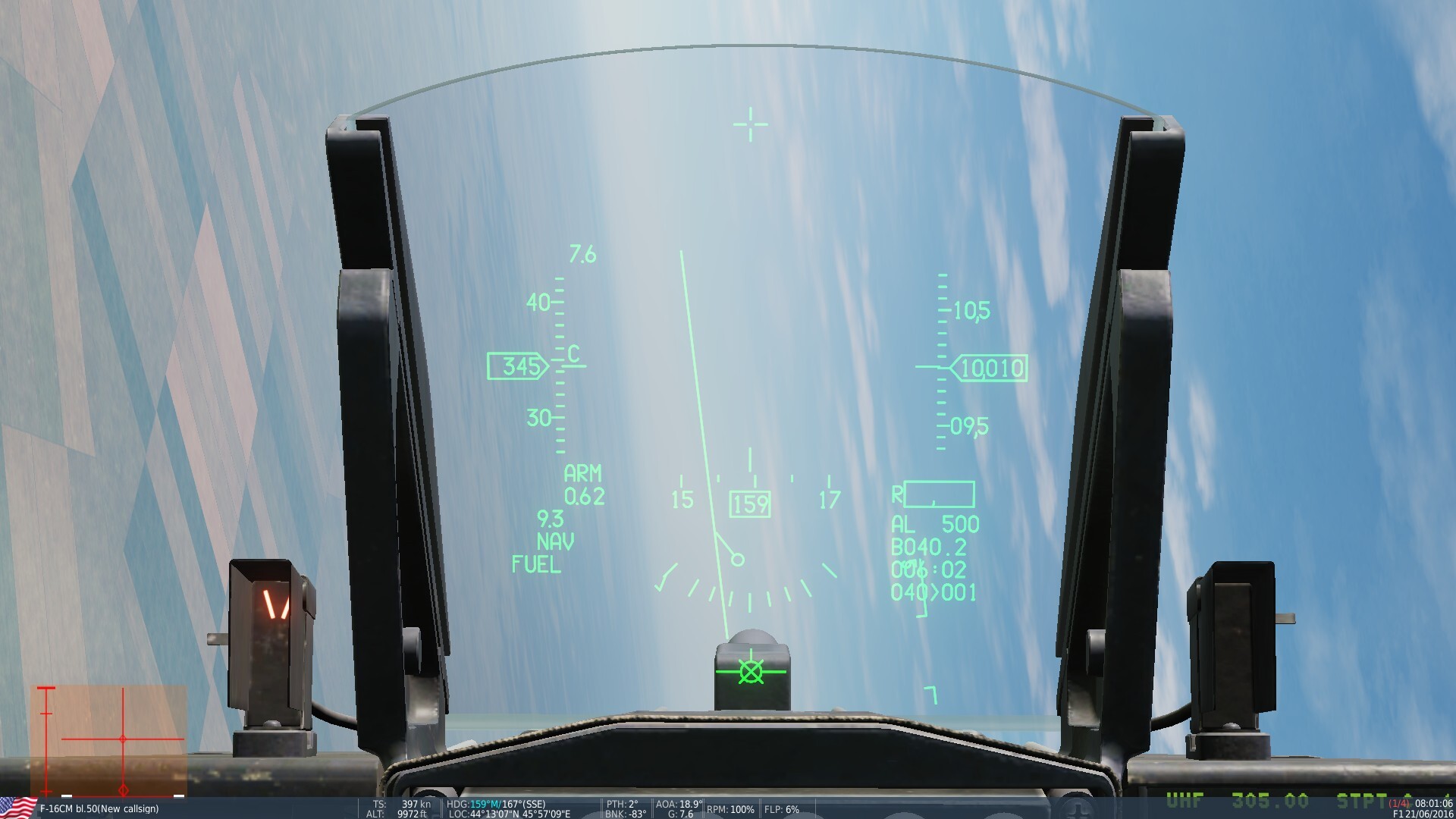
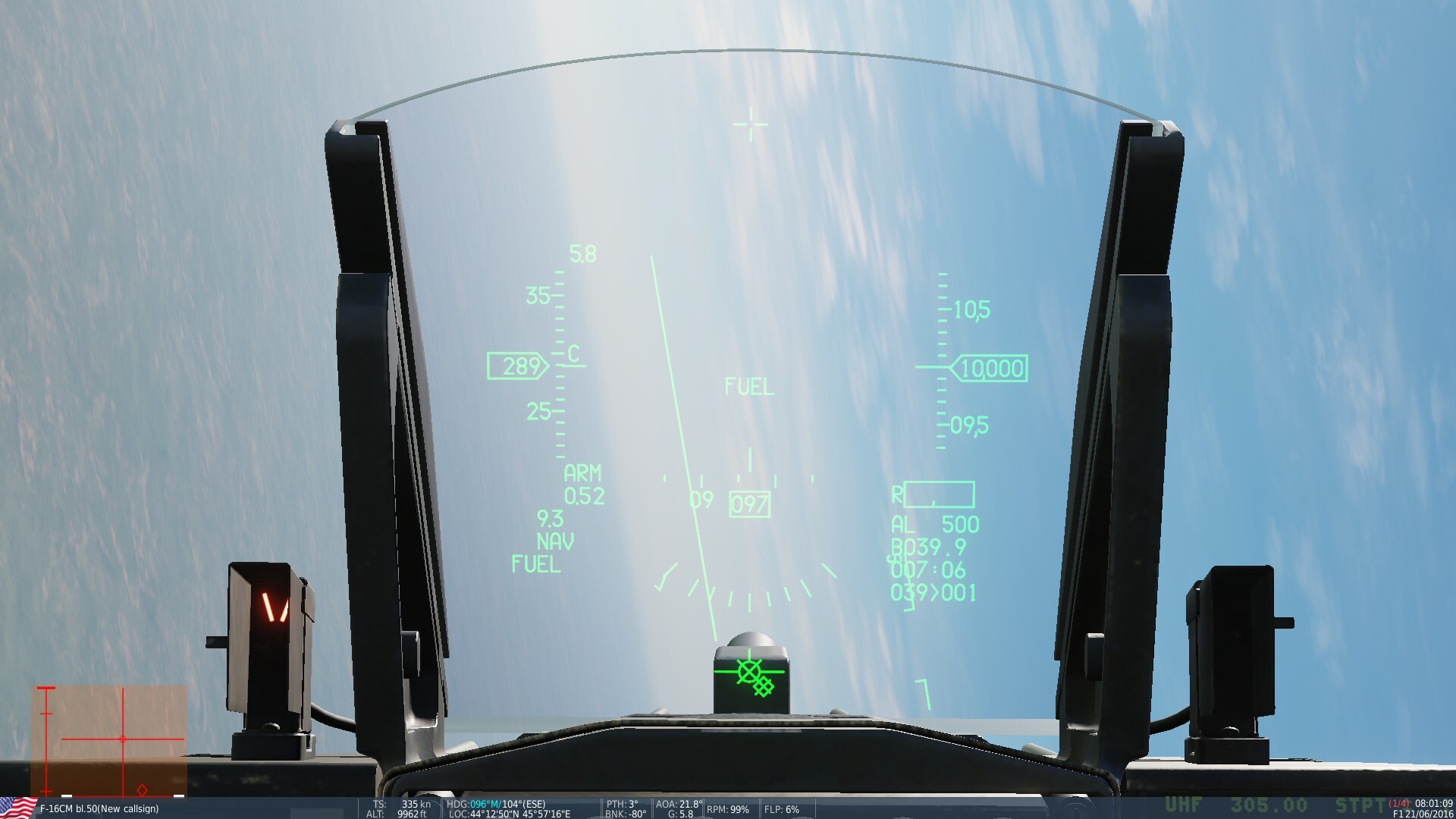
Second try with 4 data points: Mach 0.62, 0.58, 0.55 and 0.52, at 1 sec interval. SEP Calculation 1. M0.62 -> M0.58: dh = -1 ft dV = -20 KTAS = -33.76 ft/s V = 387 KTAS = 653.2 ft/s (took the average) g = 32.174ft/s^2 dt = 1s The resulting Ps = -1 - 33.76 * 653.2 / 32.174 = -686 ft/s at the speed of 387 KTAS, or 0.6 Mach. This is a bit low compared to the EM diagram above from the ED document. (Overperforms in SEP) SEP Calculation 2. M0.58 -> M0.55: dh = -2 ft dV = -22 KTAS = -37.13 ft/s V = 366 KTAS = 617.7 ft/s (took the average) g = 32.174ft/s^2 dt = 1s The resulting Ps = -2 - 37.13 * 617.7 / 32.174 = -715 ft/s at the speed of 366 KTAS, or 0.565 Mach. This is too much. So from here, the F-16 is underperforming. SEP Calculation 3. M0.55 -> M0.52: dh = -7 ft dV = -20 KTAS = -33.76 ft/s V = 345 KTAS = 582.3 ft/s (took the average) g = 32.174ft/s^2 dt = 1s The resulting Ps = -7 - 33.76 * 582.3 / 32.174 = -618 ft/s at the speed of 345 KTAS, or 0.535 Mach. This is also too much. F16 speed bleed test 10000ft -2.trk
-
I just meant you perform a max effort pull. BTW in this exact document by Eagle Dynamics, the EM diagrams of F-16 at 10000ft, GW=22000 lbs is quoted at page 23 of https://www.digitalcombatsimulator.com/upload/iblock/dcc/DCS FM principles plus MiG-29 P-47 F-16.pdf So I can definitely compare the results here without breaking the rule: The SEP at 0.74 Mach is -543 ft/s compared to -800 ft/s in the graph.
-
investigating Hornet's Slow-State Energy Bleed?
DummyCatz replied to wilbur81's topic in DCS: F/A-18C
Here's one from the NASA paper COMBAT AGILITY MANAGEMENT (CAMS) https://ntrs.nasa.gov/api/citations/19950007836/downloads/19950007836.pdf Although it is unclear what the testing conditions are, by looking at the max level speed at Ps=0 (greater than 1.3 Mach), it seems that it might be a clean aircraft or with 2 x AIM-9. But I'm not sure if it's a 400 or 402 engine. I'll take a look at this one when finished testing the SEP of F-16.
-
This is my next plan. But before that I need to practice my altitude holding skill. If anyone like to help me by taking the trackfile and fly the max ITR at lower speeds, I'll be more than happy. (The trackfile already has the correct testing conditions.) Altitude can be 0, 5k, 10k, 15k, etc..
-
In this example I chose to calculate the SEP in the range of corner plateau. This is also where the negative SEP should be the highest, at the top of the EM diagram. To my surprise, -543 ft/s is far from it, which means the aircraft bleeds less speed and therefore overperforms in SEP, at least at the corner plateau. This does not sound good for the longrunning Viper vs Hornet debate, but it's a starting point for anyone else interested in verifying the bleed rate.
-
Yes there’s a problem so it’s being investigated. I don’t think I saw any EM diagram of the F-18 that has Ps lines on it.
-
I'll share a method to quantify energy bleed rate using the SEP equation Ps = dh/dt + (V/g)(dV/dt) Reference to this equation is at Page 21 of https://dspace.mit.edu/bitstream/handle/1721.1/36378/16-885JFall2003/NR/rdonlyres/Aeronautics-and-Astronautics/16-885JFall2003/1A2F9B8F-B307-4461-83AE-9CCD658DBD50/0/aircraft_murman.pdf Given that a clean aircraft is bleeding its speed at 10000ft from 479 KTAS to 466 KTAS in a 1-sec time span, with a pretty constant bleed rate, and a tiny altitude gain of 1 ft. Then we can dial in all the elements we need: dh = +1 ft dV = -13 KTAS = -21.94 ft/s V = 472.5 KTAS = 797.5 ft/s (took the average) g = 32.174ft/s^2 dt = 1s The resulting Ps = 1 - 21.94 * 797.5 / 32.174 = -543 ft/s at the speed of 472.5 KTAS, or 0.74 Mach. So that you can check with RL figures. F16 speed bleed test 10000ft.trk
-
investigating Recurring dynamic instability bug
DummyCatz replied to DummyCatz's topic in Bugs and Problems
This is a follow up report. As said in the post, this bug fix introduces a new bug, and it's not investigated yet. There's a tendency for the aircraft to overshoot the pitch attitude upon releasing the stick. That is, after a snap pull on the stick (impulse input), and as soon as the stick returns to neutral position, the pitch motion would briefly stop for a moment, and then aircraft will keep pitching up for a few degrees before the pitch motion completely stops. Please note that there's no such tendency when pitching down. The same happens with rolling the aircraft (also shown in the track), that as soon as the roll stops, the aircraft tends to pitch up for a few degrees. This is abnormal as the FLCS is not able to dampen the pitch motion very well and suppress such uncommanded pitch-up. Thanks for your attention to the handling of the aircraft. F16 Pitch creep after pulling or just by rolling.trk -
Yeah you remind me. I'll keep an eye on the slow speed handling.
-
ITR would get slightly increased at the AOA limit. Think of a 9.3g pull. As you're bleeding speed, your AOA increases as well. As soon as the AOA exceeds 15.8 (currently 15.0) degrees, the FLCS begins to reduce your g-command (all the way to 1g) as a function of AOA, so you can no longer command 9.3g. This 15.8 acts like a threshold where your stick input starting to get reduced. BTW if you're wondering why CJ-1 manual shows 9.0g limit and 15.0 threshold, because it's the wrong manual for our CM aircraft.
-
Hi, in case it's forgotten I'd like to mention that this is not fixed as we're currently at 2.9.7. For other proof check CM-1 manual circa 2007 (not CJ-1), which the FLCS flashcard based its answer on.