DummyCatz
-
Posts
191 -
Joined
-
Last visited
Content Type
Profiles
Forums
Events
Everything posted by DummyCatz
-

can not reproduce Yaw oscillation without steering input after maneuvering.
DummyCatz replied to bies's topic in DCS: F/A-18C
This would also help and can be merged: I'm not exactly sure what's the current status of all these FM bugs now. -
I noticed that the 'wip please read roadmap' tag was removed. Does this mean the FCC OFP v10.7 functions were not planned at all despite it being the correct OFP that our Hornet should be equipped with, or the current implementation is based on an older version of FCC OFP? It just seems like the 'wip' tag was added without knowing which item was actually under wip.
- 4 replies
-
- 3
-

-
- flight model
- flight control
- (and 1 more)
-
Spin recovery switch used in displays???and some questions.
DummyCatz replied to Ala12Rv-watermanpc's topic in DCS: F/A-18C
I'm sorry to bump this up but I'd like to continue this topic due to the fact that the FM refactoring is considered finished. TLDR: switching on the MSRM can give you better roll and yaw performance at high AOA in DCS. In reality you won't usually touch the manual spin recovery mode (MSRM) switch unless you're in a spin demonstration process as described in https://trace.tennessee.edu/utk_gradthes/2312/ and https://trace.tennessee.edu/utk_gradthes/2372/. MSRM also allows you to demonstrate the notorious falling leaf out-of-controlled flight (OCF) according to the paper, otherwise impossible with the FCC OFP v10.7 upgrade, which uses a very effective sideslip and sideslip rate (beta and beta dot) feedback, driving the aileron and differential stabilators to suppress the in-phase roll and yaw oscillation characteristic of the falling leaf. MSRM turns off such feedback so that OCF can be demonstrated. But in DCS, entering MSRM allows you to achieve a better roll and yaw performance than intended, simply because the lateral and directional stability and controllability at high AOA are extremely good in game, that a yaw departure or sideslip excursion is basically unlikely aerodynamically, without the interference of FCS. There's already been a thread describing the lack of adverse yaw and other aerodynamic effects at high AOA, so you won't be worrying about them either. -
see roadmap Whats the next update to the hornet?
DummyCatz replied to fortheiy12's topic in DCS: F/A-18C
Several items left in the Flight Control Computer OFP v10.7, that were marked as WIP by ED before. Those v10.7 features would further enhance the high AOA roll and yaw capabilities of the Hornet. -
Since our Hornet has gone through the long awaited FM refactoring, I think it's time for a bug report. The trackfile is for the opposite diff-stab function. As quoted, the aileron-to-stabilator ratio begins to reduce above 30 degrees angle of attack, and reverses above 36 degrees angle of attack. So I'm expecting the diff-stab to reverse above 36 deg AOA, but it didn't: F18 opposite stab test.trk EDIT: This thread is still tagged as 'wip please read roadmap'. And now the roadmap shows that: Update flight model for ground effect, takeoff pitch effects, auto-pilot based on FPM, touch and go handling, and other remaining flight model issues [completed] So it suggest that this has not been wip at all and has slipped through the already done FM refactoring.
- 4 replies
-
- 5
-
-

-
- flight model
- flight control
- (and 1 more)
-
reported Long lasting yaw oscillation caused by the rudder
DummyCatz replied to DummyCatz's topic in Bugs and Problems
A new track for 2.9.4 showing an extremely long duration of rudder oscillation. F18 very long lasting rudder oscillation.trk -
To add to OP's argument, the primary yaw device at high AOA should be the differential stabilators, instead of rudders. Ref page 17 of https://trace.tennessee.edu/utk_gradthes/2372/ I've already checked the trackfile and didn't notice the nose move in the yaw direction either, so I suggest to do another checking for the differential stabilators. @BIGNEWY @cofcorpse Regarding how effective the anti-spin control is that utilizes adverse yaw created by both the aileron and the diff-stabs, here's a quote from page 22 of https://trace.tennessee.edu/utk_gradthes/2312/ I'm yet to see the anti-spin controls being effective in the track provided by @Figaro9, despite it being held for a total of 3 consecutive spin cycles, and finally has to resolve to splitting throttles. This may explain the lack of adverse yaw.
-
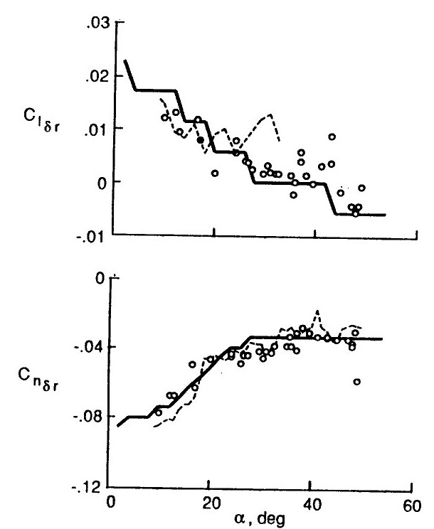
Glad to help. Now that I can resume my posting, I'd like to share the said NASA wind tunnel data and the formula behind such opposite rolls. Apart from the canted vertical stabilizers you explained earlier, a rolling moment is also created due to how the force is being applied at a higher position relative to the aerodynamic center, which acts as a pivot point. This rolling moment (coefficient denoted as Cl-δr) is opposite to the direction of yaw. But then as sideslip builds-up, the rolling moment by the rudder can be cancelled and overwhelmed by another rolling moment created by sideslip (β) due to lateral static stability (Cl-β), which is in the same direction of yaw. To simplify a bit, you can calculate the combined rolling moment coefficient (Cl) at a specific AOA, by (Cl-β * sideslip angle + Cl-δr * rudder deflection). So at low AOA, it's close to -0.1 * sideslip + 0.02 * rudder deflection. As you can see it can be negative, and also can be positive, depending on how many sideslip and rudder deflection is combined.

-
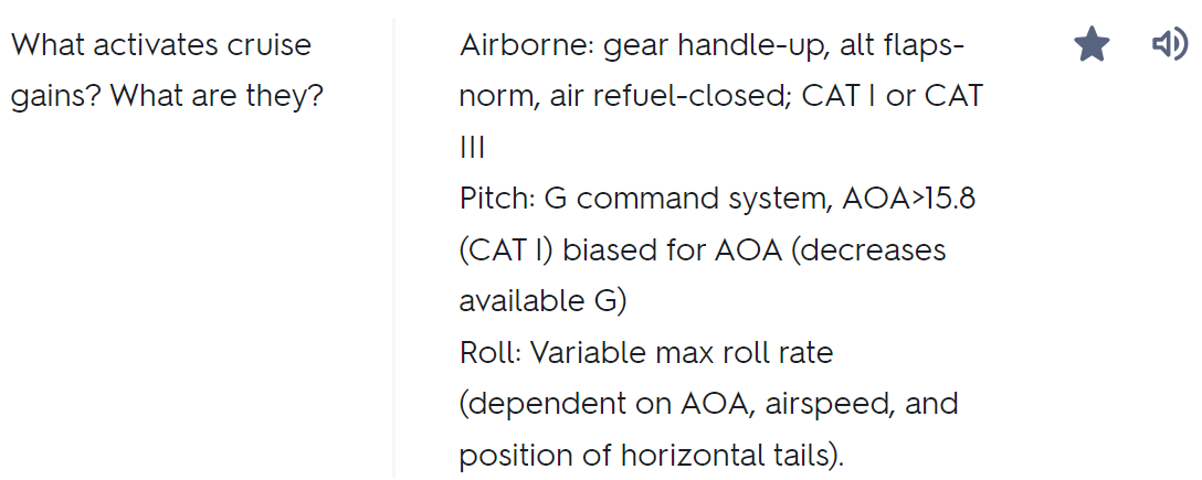
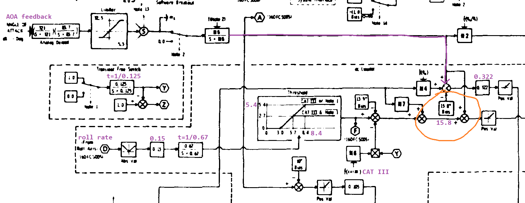
Just a minor bug in the CAT I Limiter. The blended AOA feedback bias used in the g-command system is not correct for the FLCS version we had. According to Figure 3.1 Longitudinal Control Block Diagram from the DTIC paper 'F-16 Simulator for Man-in-the-Loop Testing of Aircraft Control Systems (SIMTACS)' (https://apps.dtic.mil/sti/citations/ADA189675), the AOA bias used for an initial g-command reduction should be 15.8, but not 15.0 as currently is in DCS. This results in a lower AOA limit than expected. The figure is also backed up by the publicly available FLCS flashcard (https://quizlet.com/309832047/flcs-flash-cards/), which states that the G command system decreases available G when AOA > 15.8 (CAT I). The current 15.0 bias is seems to be used by a very old version of FLCS. 16CM g-command should not be reduced until 15.8 AOA.trk
-
reported Long lasting yaw oscillation caused by the rudder
DummyCatz posted a topic in Bugs and Problems
Currently in 2.9.2, whenever a sideslip is recreated by just rolling the aircraft at a speed around 400 knots, the rudder slaps hard to reduce the sideslip and results in a long-lasting yaw oscillation, as if yaw damping doesn't exist, which I found unacceptable from a handling quality point of view. According to section 9.1.3 Directional Auto Flap Up CAS from the NASA technical memorandum 'Simulation Model of a Twin-Tail, High Performance Airplane' (https://ntrs.nasa.gov/api/citations/19920024293/downloads/19920024293.pdf), the yaw rate (multiplied by cosine of angle of attack) feedback component is used to augment the Dutch roll damping. In the case of DCS, the oscillation is caused by the rudder itself, indicating either it is over-gained (system unstable/phase margin too low), or a wrong type of feedback (sideslip) is used according to another report https://forum.dcs.world/topic/338130-the-rudder-should-not-be-using-sideslip-feedback-for-yaw-dampening-causing-a-very-slow-yaw-response F18 yaw oscillation.trk -
need evidence Control authority and flight model RUDDER response weak?
DummyCatz replied to GumidekCZ's topic in DCS: F/A-18C
Hi, has this bug report been recognized and acknowledged? THIS is the evidence and the video was just used to illustrate the differences. -
need evidence Control authority and flight model RUDDER response weak?
DummyCatz replied to GumidekCZ's topic in DCS: F/A-18C
I'd like to differ. Any 'tweaked' FCS would subject to well-recorded, extensive flight testing, and thus the allocation of time and money. A perfect example would be from https://apps.dtic.mil/dtic/tr/fulltext/u2/a307768.pdf, back in the times when a particular version of FCC software, the OFP v10.5.1, was being flight tested. What was believed to be a very simple change resulted in a serious amount of problems. Handling qualities were dangerously degraded and a lot of time and money was spent trying to fix it. It is not feasible to develop and thoroughly flight test a 'tweaked' version of FCC software just for airshow demonstrations. -
need evidence Control authority and flight model RUDDER response weak?
DummyCatz replied to GumidekCZ's topic in DCS: F/A-18C
I'd also like to point out the yaw rate and sideslip angle achieved in this knife edge maneuver, starting at 1:47: And a brief sideslip excursion at rolling off, starting at 4:13: With the current sideslip feedback logic of the rudder that is unique to DCS, it would be impossible that such sideslip excursions are being allowed with the excessive sideslip dampening. -
As far as I can tell, this is still present with 2.9.1.
-
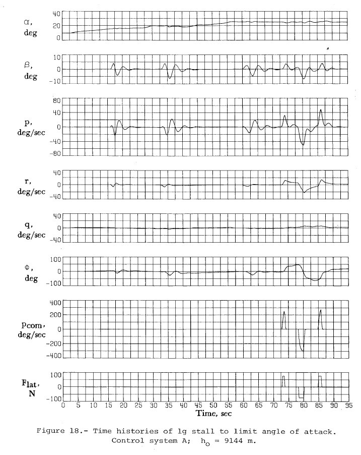
Time history of NASA FLCS control system A performing 1g stall, for example: Ref Figure 18, NASA TP-1538, https://ntrs.nasa.gov/api/citations/19800005879/downloads/19800005879.pdf
-
By referencing a publicly available FLCS flashcard (https://quizlet.com/309832047/flcs-flash-cards/), the yaw rate limiter is activated when AOA > 35° until AOA is reduced below 32°. A similar description can be found in the dash-1 manual (which is not quoted here), but I'm not seeing this behavior in DCS F-16. In the two tracks below, the activation AOA is 29° as indicated by the suddenly reducing aileron deflection upon crossing 29° AOA. This is an incorrect value by the F-16 version we had. Viper yaw rate limiter activation AOA - track2.trk Viper yaw rate limiter activation AOA.trk
-
Here's a bug in the CAT I limiter: By just performing a max effort pull to the AOA limit and reducing the throttle to IDLE, the aircraft developed an aggravating pitch oscillation by itself and eventually overshot the AOA limit and resulted in a deep stall. This dangerous behavior is not listed in the dash-1 manual. Viper AOA oscillation.trk
-
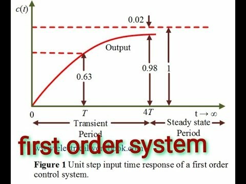
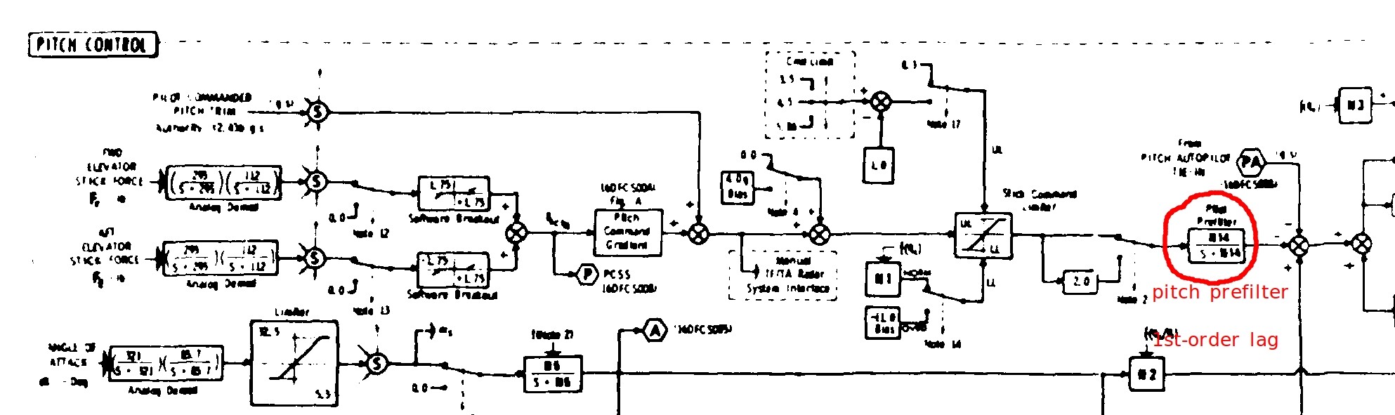
I'm not sure about the Su-33, but the lag filter in Su-27 is to reduce sensitivity in pitch control especially at higher speeds, as it poses a danger in pitch control over-sensitivity. The same can be said for the F-16 as there's a 'pitch prefilter' applied after the pitch 'stick command limiter', and there's also a known issue of pitch control over-sensitivity at transonic speeds in the F-16. According to Figure 3.1 in the paper "F-16 Simulator for Man-in-the-Loop Testing of Aircraft Control Systems", https://apps.dtic.mil/sti/citations/ADA189675, the pitch prefilter is a first-order low-pass filter (a.k.a lag filter so yes it creates lag), with a time constant of 1/N14. The gain N14 is variable, scheduled with dynamic pressure. With a dynamic pressure below 250 psf (~= 266KCAS), the time constant is 1/8.3 sec, which means the shaped g-command will be reaching 63.2% of the commanded g value in 1/8.3 seconds, given a step input. With a dynamic pressure greater than 400 psf (~= 585KCAS), the time constant is 1/6 sec, lowering the control sensitivity at higher speeds. This essentially shapes the desired first-order g-response of the aircraft, with no overshoots nor oscillations. This may explain both the lag and the g-onset. An illustration of first-order response given a step input: The location of pitch prefilter as shown in Figure 3.1, https://apps.dtic.mil/sti/citations/ADA189675
-
Update flight model for ground effect, takeoff pitch effects, auto-pilot based on FPM, touch and go handling, and other remaining flight model issues [In Progress] Hi, I've already noticed that the Flight Model and FCS has been WIP for more than 5 years. I may ask, what are the other remaining issues and has this particular bug been reported? I'm not seeing the reasoning behind the 'as stated in the road map' cuz I'm doing a bug report (regarding the rudder FCS) of an implemented feature (sideslip feedback), not a wishlist item that is not implemented (like missing logic in FCS). It's basically including all subsequent FM related bug reports into this category automatically, and it's just like saying that all the remaining issues that could possibly exist are WIP. (of course) The fix should be simple and it’s not related to the aerodynamics. Just pure control logic: Remove the sideslip feedback to the rudder, and add it to the aileron and diff-stab instead. See, it’s not a missing logic, but a bug.
-
Our current Auto Flap Up FCS implementation is using sideslip feedback to control the rudder, which I consider as a bug, because the feedback is erroneously applied to the rudder rather than to the aileron and differential stabilators. The sideslip and sideslip rate feedback should be fed to the aileron and diff-stab above 20 deg AOA, as in FCC OFP v10.7 IRL. For now, I'm seeing rudders move with sideslip changes even if AOA < 20°. Test procedure: 1. Set an extremely turbulent weather. 2. Flaps to auto. 3. Press F4 to get a closer look at the rudder 4. Check if the rudder is moving with turbulence/sideslip changes. Use active pause so that there's no lateral acceleration and yaw rate interference to the rudder. Test with AOA below or above 20 degrees. References: 1. Park, David J., "Development of F/A-18 Spin Departure Demonstration Procedure with Departure Resistant Flight Control Computer Version 10.7. " Master's Thesis, University of Tennessee, 2004. https://trace.tennessee.edu/utk_gradthes/2312 2. Mitchell, Eric John, "F/A-18A-D Flight Control Computer OFP Versions 10.6.1 and 10.7 Developmental Flight Testing: Out-of-Controlled Flight Test Program Yields Reduced Falling Leaf Departure Susceptibility and Enhanced Aircraft Maneuverability. " Master's Thesis, University of Tennessee, 2004. https://trace.tennessee.edu/utk_gradthes/2372 3. Simulation Model of a Twin-Tail, High Performance Airplane, NASA TM 107601, including a set of FCC OFP v10.1 block diagrams (https://ntrs.nasa.gov/api/citations/19920024293/downloads/19920024293.pdf) 4. NATOPS manual which is not quoted here but contains relevant info. According to the Directional Auto Flap Up CAS block diagram from reference 3, there's no sideslip or sideslip rate feedback in v10.1 as there was no sideslip measurements available to the aircraft. The feedbacks were only included in v10.6.1 (a test version of 10.7) and v10.7, together with the sideslip estimator. From reference 2 describing the sideslip estimator: From reference 1 describing the sideslip and sideslip rate feedback: Also from reference 1: Hronet rudder moves with sideslip.trk
-
need evidence Control authority and flight model RUDDER response weak?
DummyCatz replied to GumidekCZ's topic in DCS: F/A-18C
This might be the root cause: our current FCS is using sideslip feedback to control the rudder, which it shouldn't IRL in the first place. To make things worse, there seems to be a massive sideslip feedback gain being put on the rudder, causing a very weak control response. Reported here: -
A bug related to g-response and pitch instability is fixed in 2.9, which could also affect g-onset if more pitch dampening is applied: Using the example of going from 9g to 1g by releasing the stick, in DCS 2.7 and later 2.8 (with partial fix) this looked like going from 9g to 0.5g rather quickly, undershooting below 1g and then slowly creeps back to 1g, especially at speeds between 400 to 500 kts, displaying a lack of dynamic stability. Now it looks like 9g -> 2g -> 1g as a 1st-order g-response, which is a correct response type as IRL is. But the bug fix introduces pitch creep, which is to say, upon releasing the stick the nose tends to continue creep a bit more degrees until it stops.
-
investigating Recurring dynamic instability bug
DummyCatz replied to DummyCatz's topic in Bugs and Problems
The phugoid is gone in 2.9. Many thanks. Now the opposite happen and there's a tendency to overshoot the pitch attitude upon releasing the stick, but the original bug is fixed. -
need evidence Control authority and flight model RUDDER response weak?
DummyCatz replied to GumidekCZ's topic in DCS: F/A-18C
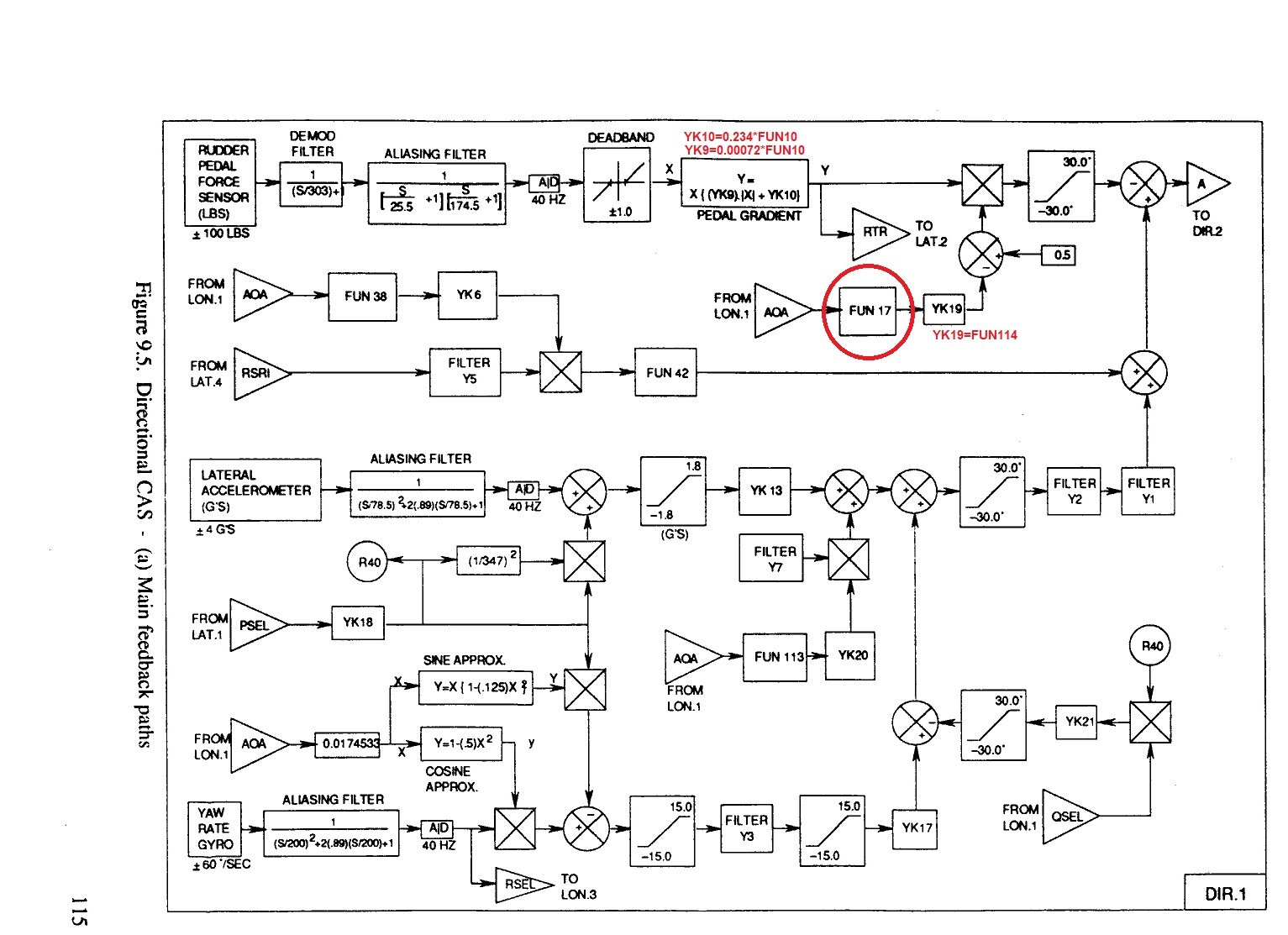
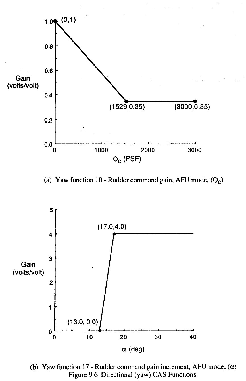
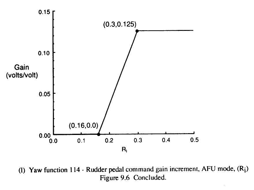
Haven't had the time to check it thoroughly but I would recommend looking into the IRL control logic for any rudder authority limitations. A good place to start is the paper 'Simulation Model of a Twin-Tail, High Performance Airplane' by NASA (https://ntrs.nasa.gov/api/citations/19920024293/downloads/19920024293.pdf). Page 113 contains detailed description of the Directional Auto Flap Up CAS with a set of control block diagrams of FCC OFP v10.1 directly from the MDC report. Page 115 and beyond detailing the block diagram and gain schedules: (Ri = dynamic pressure Qc / static pressure Ps) So your pedal command is effectively shaped by the PEDAL GRADIENT, that uses Function 10 to reduce the gradient at higher dynamic pressure (or airspeed), which prevents exceeding the vertical tail load limits. Then the command is multiplied by (0.5 - Function 17 * Function 114), and is limited to -/+30°. Function 17 increases the gain at higher alpha, while Function 114 increases the gain at higher mach number. The more gain they produces, the more reduction to the command ratio. The idea is to prevent medium to high alpha yaw departures caused by misplacing the pedal. This concludes the command path and may explain why the rudder command is reduced. The remaining paths are feedback paths, like yaw rate feedback and lateral acceleration feedback, that are used to enhance directional static stability (provides turn coordination) and yaw rate dampening. A higher feedback gain could increase stability and dampening effect, but could also lower the yaw response and destabilize the system, causing the rudder to oscillate. Sideslip and sideslip rate feedback is only added in OFP v10.7, and is not provided to the rudder, but to the aileron and diff-stab. But I found no indications that any v10.7 logic is implemented in DCS. Cheers.
-
Hi, This thread is about the FCC OFP version 10.7 control logic implemented in DCS, and it's missing important features. Several observations (currently as of 2.9.4) show that a core function, which is described as 'Opposite Differential Stabilators for Roll', is not implemented. This function utilizes adverse yaw to generate yaw rate, enhancing roll coordination and performance at high AOA. A description of opposite diff-stab function, quoted from reference [2]: A description of the sluggish roll performance of v10.5.1, quoted from reference [1]: Video evidence of Opposite Differential Stabilators, from 0:42: This would be very useful in generating proverse yawing moment in the direction of intended yaw, increasing the yaw/sideslip maneuverability of the Hornet at elevated AOA, which is currently lacking in DCS. References: 1. Mitchell, Eric John, "F/A-18A-D Flight Control Computer OFP Versions 10.6.1 and 10.7 Developmental Flight Testing: Out-of-Controlled Flight Test Program Yields Reduced Falling Leaf Departure Susceptibility and Enhanced Aircraft Maneuverability. " Master's Thesis, University of Tennessee, 2004. https://trace.tennessee.edu/utk_gradthes/2372 2. Park, David J., "Development of F/A-18 Spin Departure Demonstration Procedure with Departure Resistant Flight Control Computer Version 10.7. " Master's Thesis, University of Tennessee, 2004. https://trace.tennessee.edu/utk_gradthes/2312 3. NATOPs manual which is not quoted here but contains relevant info.
- 4 replies
-
- 8
-
-
-
- flight model
- flight control
- (and 1 more)