DummyCatz
-
Posts
191 -
Joined
-
Last visited
Content Type
Profiles
Forums
Events
Everything posted by DummyCatz
-
 By switching to Take-off and Landing Gains, you essentially command pitch-rate with your stick, instead of G. And the FLCS will hold 0 pitch-rate (instead of 1g as in Cruise Gains) when hands off stick. This is beneficial to flying qualities at lower speeds (e.g. < 400 knots) so you can manipulate pitch-rate more precisely. The only difference in FLCS logic between using the AIR REFUEL button and lowering the gear is that, the AIR REFUEL button will not lower the flaps automatically.
 -
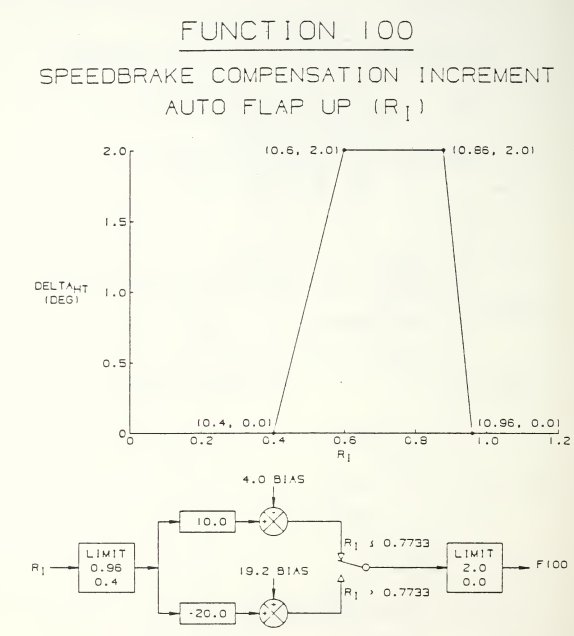
@Harley Just tested with DCS 2.9.15.9408, the speedbrake-to-stabilator interconnect logic is still working at low speeds, which contradicts Function 100. You can confirm this by using active pause and then experiment with speedbrake commands at different Mach Numbers. In this case, the g-transient is purely caused by the FCS itself, and is a wrong behavior.
-
OP asked if there is a definition for the correlated degrees of travel that the pitch correction input from the elevons is supposed to be. I gave the answer. Sometimes NATOPS doesn't give the full picture. I'm not sure what you're trying to argue here. I am not the one who disputed the word 'Alleviate', as with all open-loop linear compensation logics. The point here is to provide an overall system description when NATOPS cannot be posted on the forum, and the fact that it only works in a limited range of Mach Numbers (high subsonic speeds). It can be inferred that the pitch bobble is not that pronounced in low subsonic speeds, where it doesn't require compensation by the FCS. Also, the interconnect command is on/off in response to speedbrake solenoid valve command, meaning it's either on or off in response to the opening and closing action, but not actual positions. This clarifies OP's doubt. The cited NASA report is for FCC OFP v10.1, and the logic should be the same from v10.1 to v10.7 as there's no documented change in speedbrake-to-stabilator interconnect function.
-
According to the NASA Technical Memorandum 107601 (https://ntrs.nasa.gov/citations/19920024293), a speedbrake-to-stabilator interconnect (Function 100) is incorporated to alleviate g transients for speedbrake extension/retraction. The interconnect command is on/off in response to speedbrake solenoid valve command. The magnitude of the input command air data scheduled. The interconnect command is lagged through a first order low-pass filter with the time constant scheduled with air data and as a function of speedbrake extension or retraction. The speedbrake extend time constant is less than the speedbrake retract time constant. The schema of Function 100: In which, Ri (pressure ratio) = dynamic pressure / standard atmosphere pressure. As you can see, the delta HT (horizontal tail) compensation is only active in a range of Ri from 0.4 to 0.96, which roughly corresponds to 0.7 - 1.1 Mach. Other references: https://www.semanticscholar.org/paper/Development-of-a-mathematical-model-that-simulates-Rojek/0fde51d56d310669dd67ae8520a0650989a91156 https://archive.org/details/developmentofmat00roje/page/n3/mode/2up distribution unlimited.

-
There has been a pitch creep bug that is related to the issue you described and is still being investigated.
-
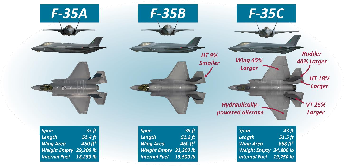
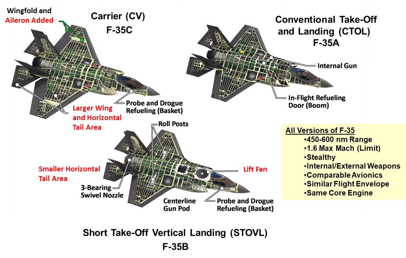
According to the public papers by Lockheed Martin, the aerodynamic differences in wing area and horizontal tail surface area among the versions, and the differences in basic stability and control power, are not trivial. Designing control laws for three versions at the same time, without standing up independent development teams, required creative approaches in order to meet program schedules. That's why a unified model-based, dynamic inversion approach using auto-generated code is chosen. This technique eliminates the need to linearize the aircraft system at specific flight conditions and develop extensive gain schedules, which is a time-consuming process in a more traditional FBW design. Instead, it allows designers to directly specify the desired aircraft response, accommodating the nonlinear dynamics of each variant. It adapts to aerodynamic, control surfaces and propulsion differences, through an onboard model (OBM) rather than requiring entirely separate control laws, ensuring similar flight characteristics and meeting program efficiency goals. But still, here are some interesting unique FM differences: The F-35C is less prone to deep stalls (same as those experienced by F-16) compared to the other variants, even in worst-case conditions. This is due to its larger horizontal tail, which contrasts with the STOVL variant’s higher susceptibility to deep stalls due to its smaller tail, and the CTOL variant’s weak deep stall potential only at extreme aft center of gravity (CG) positions with low fuel. On the other hand the F-35C posed the most significant challenges in departure resistance (the ability to resist uncontrolled flight departures). For example, During a test maneuver, the aircraft experienced a rapid, uncommanded roll reversal due to adverse sideslip, aggravated by its unique features like aileron deflection, increased wing span, and the proximity of the wing and horizontal tail. This was addressed with control law (CLAW) modifications and updates to the aerodynamic onboard model (OBM). At around 0.75 Mach and near stall AOA, the F-35C exhibited poor sideslip control during maneuvers, leading to larger-than-desired sideslips. While control was maintained, CLAW updates and additional low-altitude testing were implemented to mitigate potential excessive loads. The F-35C showed unique anomalies at lower altitudes (e.g., below 20,000 feet), where errors in Mach-dependent coefficients became more pronounced due to higher dynamic pressure and slower deceleration rates. This necessitated additional testing down to 7,000 feet MSL, unlike the CTOL and STOVL variants, which did not exhibit similar issues. The extra effort ensured the F-35C was cleared for unrestricted high AOA maneuvering at all altitudes. Just some examples. Fig. 1 of https://arc.aiaa.org/doi/10.2514/6.2018-3516 (F-35 Flight Control Law Design, Development and Verification) Fig. 2 of https://arc.aiaa.org/doi/10.2514/5.9781624105678.0525.0574 (F-35 High Angle of Attack Flight Control Development and Flight Test Results)
-
High AOA after making a loop when below 280 KTS
DummyCatz replied to TunisianRaptor's topic in DCS: F-16C Viper
This is caused by inertia coupling and is recently introduced, so deep stall is more likely to happen. Have you tried pitch rocking technique? -
New FM, pitch oscillations on supersonic speed
DummyCatz replied to Blackfyre's topic in Bugs and Problems
Depends on the progress of the mentioned FM/FCS refactoring. -
What's the procedure for a crosswind landing?
DummyCatz replied to Hyperlynx's topic in DCS: F-16C Viper
The beta (AOS) feedback in the DFLCS is not functional in take-off & landing gains. -
That’s interesting. Might need to test 1g SEP at low speed too, to see if the fix caused discrepancies in other part of the diagram.
-
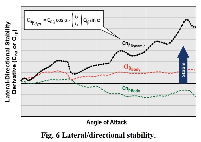
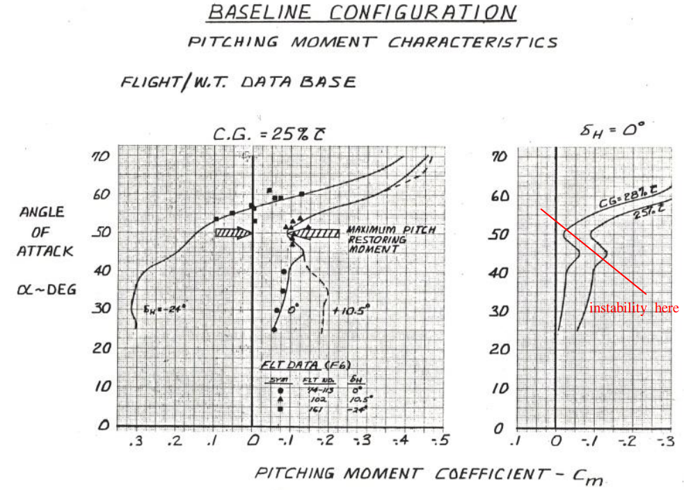
Regarding the notion of deliberately hiding classified aspects of high AOA modeling - this would be detectable. Flight dynamics are deeply interconnected, and any artificial limitations, inaccuracies or simplifications would create detectable inconsistencies. Knowledgeable users can identify these discrepancies using publicly available information, as demonstrated through existing flight model bug reports that rely solely on public sources. (e.g. some of my F-18 FM reports.) The core challenge remains implementing both the complex high AOA aerodynamic modeling with its asymmetric moments, and the NDI-based flight control system. However, we do have some useful reference points. The AIAA papers provide stability derivative and control power trends (Cm, Cn, Cl diagrams) that, even without absolute values, still reveals the general shape of those coefficients of aerodynamic moments. So we can know the relative control effectiveness and aircraft static stability across AOA ranges. For example the lateral-directional stability derivatives of the F-35 from Fig 6 of the AIAA paper quoted above, that you know when the Cn-beta dips into negative values, the AOA should be somewhere around 25-30 deg. What makes this particularly interesting is how the NDI system essentially defines the aircraft's maximum allowable performance envelope. We know the system aims to maximize performance within safety boundaries, prevent departures while minimizing interference, and deliver consistent handling qualities. This suggests that if you can accurately model the basic aerodynamic behavior using scaled/estimated data from public trends, as well as the NDI control architecture's fundamental principles with departure prevention and departure recovery modes, you could potentially achieve a reasonable approximation of the aircraft's actual performance characteristics, since the NDI system would naturally optimize control within whatever envelope you've defined. While exact values remain classified, the general behavior and performance could be reasonably reconstructed through careful implementation of the documented NDI principles and known aerodynamic trends.
-
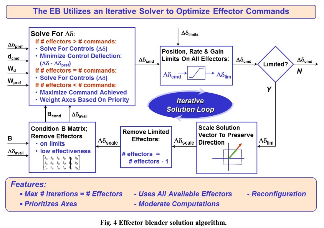
Thanks for the excellent write up. The F-35 IRL is indeed using INDI, as the engineers had to deal with significant challenges from onboard aerodynamic model (OBM) mismatches, especially in high AOA as well as transonic regions. In DCS, you could theoretically have a naive NDI system using the exact same aerodynamic model that's driving the simulation - creating a perfect match between the OBM and the simulated aircraft behavior. This would be "cheating" in the sense that it eliminates one of the fundamental challenges that makes real NDI implementation difficult. But this raises some other interesting questions about simulation fidelity: Should ED deliberately introduce model mismatches to more accurately represent the real system's limitations? Could using the same model for both simulation and control (OBM) make the aircraft behave more like an idealized mathematical model than a real machine, so that the handling characteristics is in a way unrealistically and overly optimistic, with the resulting control allocations being too "precise" that doesn't match the real F-35's handling qualities? The most computational cost probably comes from an iterator, like the pseudo-inverse iterative calculation of the Effector Blender (EB), as explained in https://arc.aiaa.org/doi/10.2514/6.2018-3516 Compared to the traditional control surface mixer, whose control logic will only be running one time per simulation cycle, the EB logic will be running several times per simulation cycle, due to the iterative solver. It will indeed be cool to see how ED will handle this.
-
Some point of view to think about: While we'll always be dealing with approximations in DCS, the challenge here isn't just about fidelity - it's about creating a basic NDI architecture that captures the fundamental behavior of the real system. The F-16/F-18 approximations can be built on known control structures, while the F-35 would require essentially designing a new NDI implementation from scratch. The F-16 and F-18's FBW simulation take benefits from the well-known and public control laws (e.g. NASA TP1538 and DTIC ADA189675 for F16 and NASA TM107601 for F18) with well-documented PID controllers and by-the-book gain schedules and filters, that you can even 100% replicate the logic according to the diagram. But yet, look at the current and previous state of FCS problems in DCS F-16 and F-18 would give you an idea of how hard it is to implement even a PID-based control structure. The F-35's NDI presents a fundamentally different challenge compared to the traditional PID-based control architectures used in those traditional FBW aircraft. Without access to the actual onboard model data or knowing how the effector blender optimizes control allocation, creating even a rough approximation would require making many assumptions.
-
Given the upcoming DCS F-35A module and after reading through some LM's technical papers about its performance and flight control system designs, I'd like to discuss what I believe might be the most challenging aspects of implementing the F-35's unique flight model and control laws, particularly its NDI (Nonlinear Dynamic Inversion) system. From what I understand, this would be the first implementation of an NDI-based flight control system in DCS. The key challenges I see are: 1. Onboard Model (OBM) and aerodynamic model. The F-35's NDI relies heavily on a detailed onboard model (OBM) of the aircraft's mass properties and stability/control characteristics. How ED is going to handle the complex aerodynamic modeling, especially in the high AOA and transonic regime is crucial, where you have: Nonlinear control effectiveness Strong control surface interactions Complex vortex systems and flow separation effects Transonic roll-off phenomena 2. Real-time Control Solution Computation. Unlike traditional scheduled-gain FBW systems, the NDI system computes control solutions on the fly. Does the DCS engine architecture allow for this kind of real-time computation without impacting performance? 3. Effector Blender Implementation. The effector blender needs to: Compute optimal control surface allocation in real-time Handle control priority shifts (like yaw vs. pitch priority for horizontal tails) Manage control surface interactions at high AOA Deal with control surface saturation and overflow conditions 4. Auto Recovery Systems. The integration of: Automatic Pitch Rocker (APR) for deep stall recovery. (Yes, the F-35 have deep stalls just like the F-16) Anti-spin modes Complex mode transition logic Adaptive filtering systems for yaw rate control It's also interesting to see how ED will handle the transition between different control modes (like the shift from traditional roll command to yaw rate command at high AOA) while maintaining the "feel" of the real aircraft. This would be a unique kind of FM and FCS to witness in DCS. Cheers and take a read at https://arc.aiaa.org/doi/10.2514/5.9781624105678.0525.0574 (F-35 High Angle of Attack Flight Control Development and Flight Test Results)
-
One thing to keep in mind though, is that the 171,000 kg limit is a force being applied perpendicular to the wing (body-fixed coordinate system, or body axes frame of reference), while the lift is perpendicular to the velocity vector (velocity coordinate system, or wind axes frame of reference). That means, the force being applied perpendicular to the wing = total lift * cos(AOA) + total drag * sin(AOA). Ny is also in the direction perpendicular to the wing, and is not aligned with the lift. So Ny * weight = total lift * cos(AOA) + total drag * sin(AOA), which has a 171,000 kg limit.
-
Funnily enough, I posted my methodology of testing the SEP in that thread, which eventually resulted in the bug report that contributed to the progress of fixing this thing.
-
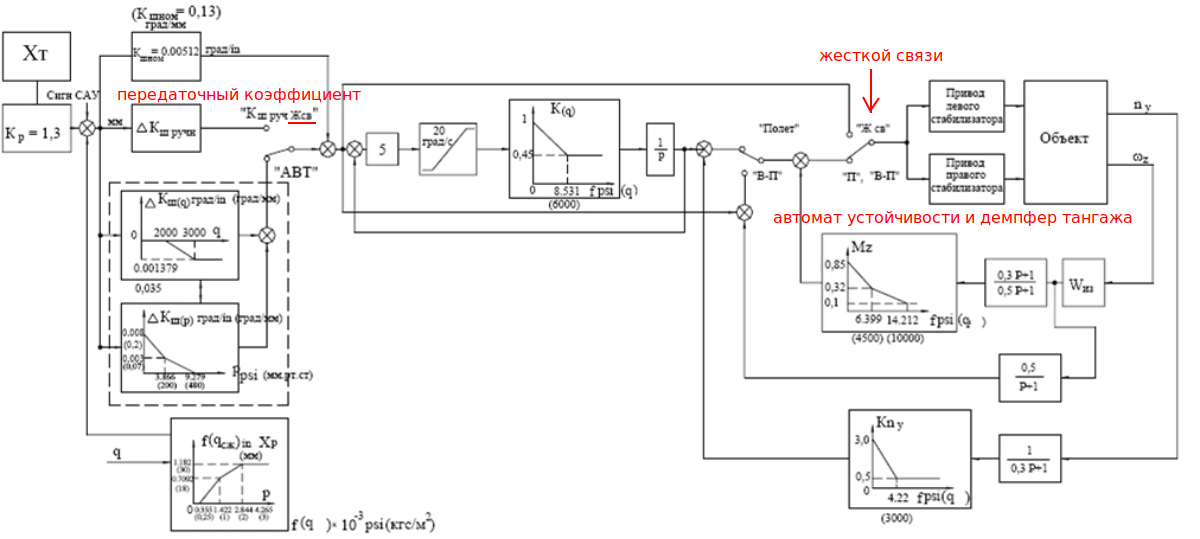
Maybe I was wrong but I'm not seeing any values being used by the FMOptionsSu27.lua? cs_q_ny_max = 17000 cs_q_ny_min = 1600 cs_Kny_max = 0.15 cs_Kny_min = 0.031 whereas in the diagram cs_Kny_min = 0.5, cs_Kny_max = 3.0, cs_q_ny_min = 0, cs_q_ny_max = 3000. Like wisely, cs_q_wz_max = 26000 cs_q_wz_min = 2000 cs_Kwz_max = 0.72 cs_Kwz_min = 0.4 In the diagram there are three split sections of scheduling where q = 0, 4500, 10000 and Kwz = 0.85, 0.32, 0.1. I'm also not sure where does cs_Kwz_g = 3.8*0.7 come from.
-
Now that we have a clean view of the graph, we can use the realistic numbers from the Kwz and Kny schedules. I think there's a FM options file out there that allows us to change those values.
-
это правильно в соответствии со схемой
-
fixed high AoA roll when going less than 300kias
DummyCatz replied to 777coletrain's topic in Bugs and Problems
I can see there're two bugs that were merged together. OP was talking about the susceptibility to a departure and subsequent deep stall, and is related to the recent bug fix of: Fixed: Impossible to enter a deep stall. While the other bug was about excessive yaw induced by roll that was related to the recent bug fix of: Fixed: Excessive YAW With Roll Inputs in Landing Config. Just make sure both are taken care of. -
Yes I just meant the distance between the center of the stick circle and the pushrod symbol. Now I noticed the gap. It is indeed hard to notice.
-
Thanks. This does sound reasonable.
-
It's actually 50% of normal fueling, which is (4160 + 1060) / 2.
-
high AoA roll when going less than 300kias
DummyCatz replied to 777coletrain's topic in Bugs and Problems
Just try pulling and rolling the aircraft to its AOA limit at high altitudes. This would maximise the possibility of getting into one. -
Thank you for your prompt response and Happy New Year. I appreciated the detailed points you’ve raised. While your point about the cumulative impact being minor for prolonged flight path is valid, dynamic pitch pointing (and unloading) capabilities would certainly benefit from the 30% increase/decrease in Ny. This would also explain why the data graph of performing a Cobra posted by MA_VMF above doesn't agree with the Ny and/or AOA data seen in DCS, which could be a real question posed by other users who would love to compare such data and diagrams. I think this is more of a question as of to what extent the FM realism should achieve in individual aircraft. Modules like the F-16 and F-18 also benefit from extensive public data (e.g. NASA wind tunnel data for both the F-16 and F-18), which can create a disparity in FM fidelity. The NASA public data also include aerodynamic coefficient derivatives such as Czq and Cz_alpha_dot (for example in NASA TM 107601 for the F-18), which inherently places them at an advantage in terms of potential FM realism, if you consider fairness. I would personally prefer realism to fairness as long as the price are justified. But it's your decision afterall. You mentioned discrepancies in the trim data (~70° α_trim_max from the article vs. ~40-50° in DCS). As a user, I cannot independently verify the trim data used in the Su-27 FM. While the TsAGI’s article shows higher trim angles, which of course can be indicative of a very aft CoG, as there's no CoG data shown in the article. But there's other points that I based my speculations on: There's uncommanded pitch-down behavior at negative AOA in DCS Su-27, which is a very noticeable unstability. I'm using this as a basic feeling to the negative static margin. Observations from 1g stall tests in DCS suggest the Su-27 exhibits behavior closer to a statically stable aircraft, if compared to a F-15, as there's no noticeable uncommanded pitch motions.This behavior aligns with positive static stability characteristics rather than the neutral or slightly negative stability expected from a relaxed static stability design like the Su-27. I mentioned the F-16 is because as a typical behavior, it exhibits uncommanded pitch-up with a neutral elevator at 40-50° AOA (and the F-18 too as there's a Cm curve out there), due to the elevator stall, if kept at neutral position, and would cause the aerodynamic center to shift forward, resulting in a decrease in static margin. This phenomenon is pretty common to those aircraft, but I won't know the behavior of Su-27 without any data for sure. Appendix. Cm curve of F-18C from https://www.scribd.com/document/721840808/F-18-HORNET-S-NEST