DummyCatz
-
Posts
191 -
Joined
-
Last visited
Content Type
Profiles
Forums
Events
Everything posted by DummyCatz
-
Figure B1-1 (sheet 1). Note that the basic aircraft drag index is different in the USAF manual (0/0) compared to the ones in HAF manual.
-
@TOT_53 The payload in your F-16 test DCS Word Test Data (silver.ru) seems not correct. According to CJ-1-1, Drag Index of a basic aircraft includes AIM-9L tip missiles on 16S210 launchers. It's not a completely clean aircraft.
-

investigating Recurring dynamic instability bug
DummyCatz replied to DummyCatz's topic in Bugs and Problems
Track is attached to OP, and it includes 4 tests at different speed/alt. The third test, starting at 540 kts, shows a correct 1st order g-response. The rest of them are all incorrect behavior with a noticeable phugoid. -
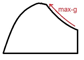
cannot reproduce the Viper not able to hold 9.3g while bleeding speed
DummyCatz replied to DummyCatz's topic in Bugs and Problems
Track is attached to OP with a condition of DI=0, GW around 26,000 lbs and an altitude just above sea level. Notice the decelerating max-g pull before AOA hitting 15 deg. -
cannot reproduce the Viper not able to hold 9.3g while bleeding speed
DummyCatz replied to DummyCatz's topic in Bugs and Problems
Hi, holding 9.3g does not mean holding speed as well. The test is to check the top right portion (max-g line) of the EM diagram, whether the F-16 is able to hold and keep a max g-limit while bleeding speed or increasing speed. As long as the EM diagram of the same test condition shows that the max-g line is there and attainable, it's worth to test. From an aero and FLCS point of view, the max-g is attainable when: 1. AOA < 15 deg (CAT I) where FLCS starts to decrease g-limit. 2. The horizontal stab doesn't use up all its authority (travel range) in supersonic flight when the aerodynamic center moves backward. I may need more tests (and yes tracks) to come to a conclusion, but my initial tests do suggest that it's somewhat related to the bleed rate, that if the aircraft bleed its speed during a max-g pull, the attainable max-g would be reduced by 0.1-0.3g. This is pretty common in a BFM situation.
-
The dynamic pitch stability is degraded over around 400 kts, indicating a recurring bug that was fixed some time ago. The g-response is no longer a first-order response. New track is attached. Viper phugoid at speeds.trk
-
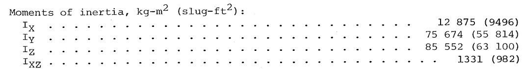
correct as is Yaw and Pitch inertia values are Reversed.
DummyCatz replied to FusRoPotato's topic in Bugs and Problems
Never heard of that. IIRC the Angle of Sideslip feedback function is unavailable for the FLCS when AOA < 10 deg. -
As mentioned in a previous flight control system mini-update, the Viper was able to hold 9.3g when energy sufficient, but initial tests suggest that max-g limit would be reduced by 0.1-0.3g while bleeding speed, which is usually the case in a BFM situation. Track is attached. Viper not holding 9.3g while bleeding speed.trk
-
You can work it out with the SEP equation posted above. Take note of the test conditions in the EM diagram and do the following: 1. Find out the speed of sound in ft/s at the altitude of test condition. Try using the Standard Atmosphere chart from -1-1. 2. Select a mach number you want to test, and convert it to ft/s by multiplying the speed of sound in ft/s. This is the 'V' in the equation. 3. Select a Ps curve you want to check against. With mach number and Ps, you can pinpoint the required normal load factor in the EM chart. 4. Calculate bleed rate dV/dt using formula Ps * 32.174(gravity constant) / V. This is in ft/s^2 for now. 5. Convert it to knots per sec to be tested against. Set HUD unit to KTAS as well. And you're good to go with the bleed rate testing.
-
I'll share an example using the above equation Ps = dh/dt + (V/g)(dV/dt) Given that the aircraft is bleeding its speed from 400 KTAS to 396 KTAS in a 1-sec time span, with a pretty constant bleed rate, and a tiny altitude loss of 5 ft. Then we can dial in all the elements we need: dh = -5ft dV = -4KTAS = -6.75ft/s V = 398KTAS = 671.75ft/s (took the average) g = 32.174ft/s^2 dt = 1s The resulting Ps = -145.93 ft/s at the speed of 398KTAS.
-
Bleed rate (dV/dt) can be used to calculate Specific Excess Power (Ps) to be compared with those in EM diagrams. Ref Chapter 5. Altitude Change: Climb and Guide – Aerodynamics and Aircraft Performance, 3rd edition (vt.edu) Ps = dh/dt + (V/g)(dV/dt) Assuming no altitude loss, the equation can be rewritten into Ps = (V/g)(dV/dt), while Ps, g and V are in ft/s, and (dV/dt) in ft/s^2.
-
correct as is Yaw and Pitch inertia values are Reversed.
DummyCatz replied to FusRoPotato's topic in Bugs and Problems
The inertia figures come from page 43, NASA TP-1538 (https://ntrs.nasa.gov/citations/19800005879) dated December 1, 1979. As for the while paper, here's one sitting in the wish list:
-
Are we talking about flight envelope OR handling characteristics? Seems two different things to me.
-
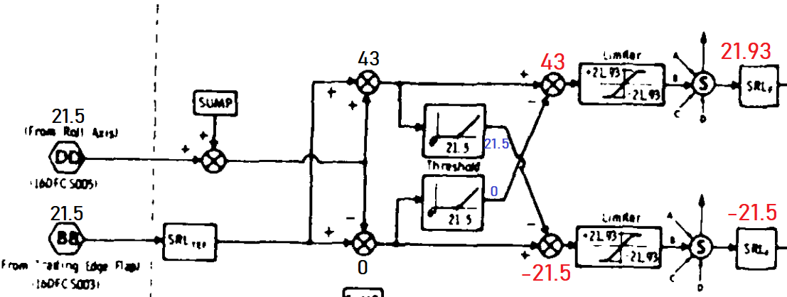
correct as is Incorrect aileron deflection with gear lever down
DummyCatz replied to bkthunder's topic in Bugs and Problems
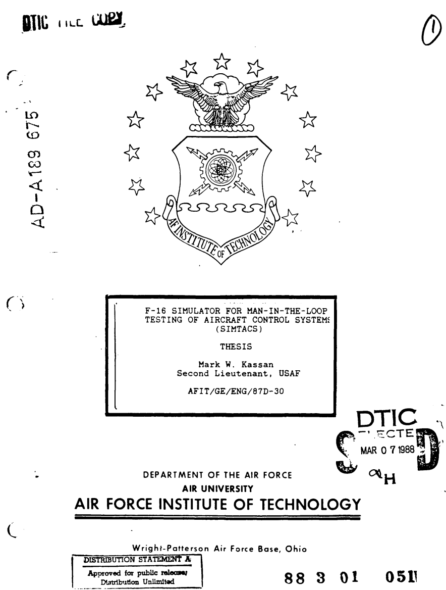
I stand corrected. A more careful look at the Control Surface Mixer diagram in Page 25, https://apps.dtic.mil/sti/pdfs/ADA189675.pdf reveals that the aileron does go over the horizontal position. -
correct as is Incorrect aileron deflection with gear lever down
DummyCatz replied to bkthunder's topic in Bugs and Problems
Seems that there's indeed no ratio/gain changes to the roll command, or any other logic changes to cause the flaperons to be deflected upwards with TEF down, so yeah the flaperons should at max go to neutral position. A little more references to back it up: https://apps.dtic.mil/sti/citations/ADA202599 https://apps.dtic.mil/sti/citations/ADA189675 ----- Edit: NVM. The DCS implementation seems correct. The Surface Command Mixer is responsible of mixing and enhancing the commands from the roll channel, so with both roll command and TEF command outputting a value of 21.5, the left and right aileron should be at -21.5 and 21.93 each. Quoting page 25 of A189675 (https://apps.dtic.mil/sti/pdfs/ADA189675.pdf) Provided that the document is dated 1988, apart from the public link I'll also post the cover and distribution statement:
-
I cannot think of a more laggy system other than a Su-27, which deploys a lag filter to the stick command that has a very low filter rate (=high time constant).
-
I can see two separate bug reports here which may not be linked to each other. The first one is an aerodynamic issue, about not being able to hold the Knife Edge while maintaining the nose above the horizon, at a relatively low AOA. The problem seems to be related to the lateral forces that are created by the rudder (delta CY-rudder). The second one is about the FLCS limiting logic, which is related to AOAs above 14 deg where the rudder authority starting to be reduced by the system. And you certainly won't be executing a Knife Edge when flying above 14 deg AOA.
-
Brunner Force Feedback Joystick Base
DummyCatz replied to Mozart's topic in PC Hardware and Related Software
The spring force is a constant 7.0 lbs/inch per NASA TM 107601 (or 7.4 per ADA256522 as Curly posted). https://ntrs.nasa.gov/api/citations/19920024293/downloads/19920024293.pdf https://apps.dtic.mil/sti/pdfs/ADA256522.pdf This is correct. Stick travel vs force is fixed. -
Real life Hornet stick force
DummyCatz replied to markturner1960's topic in Controller Questions and Bugs
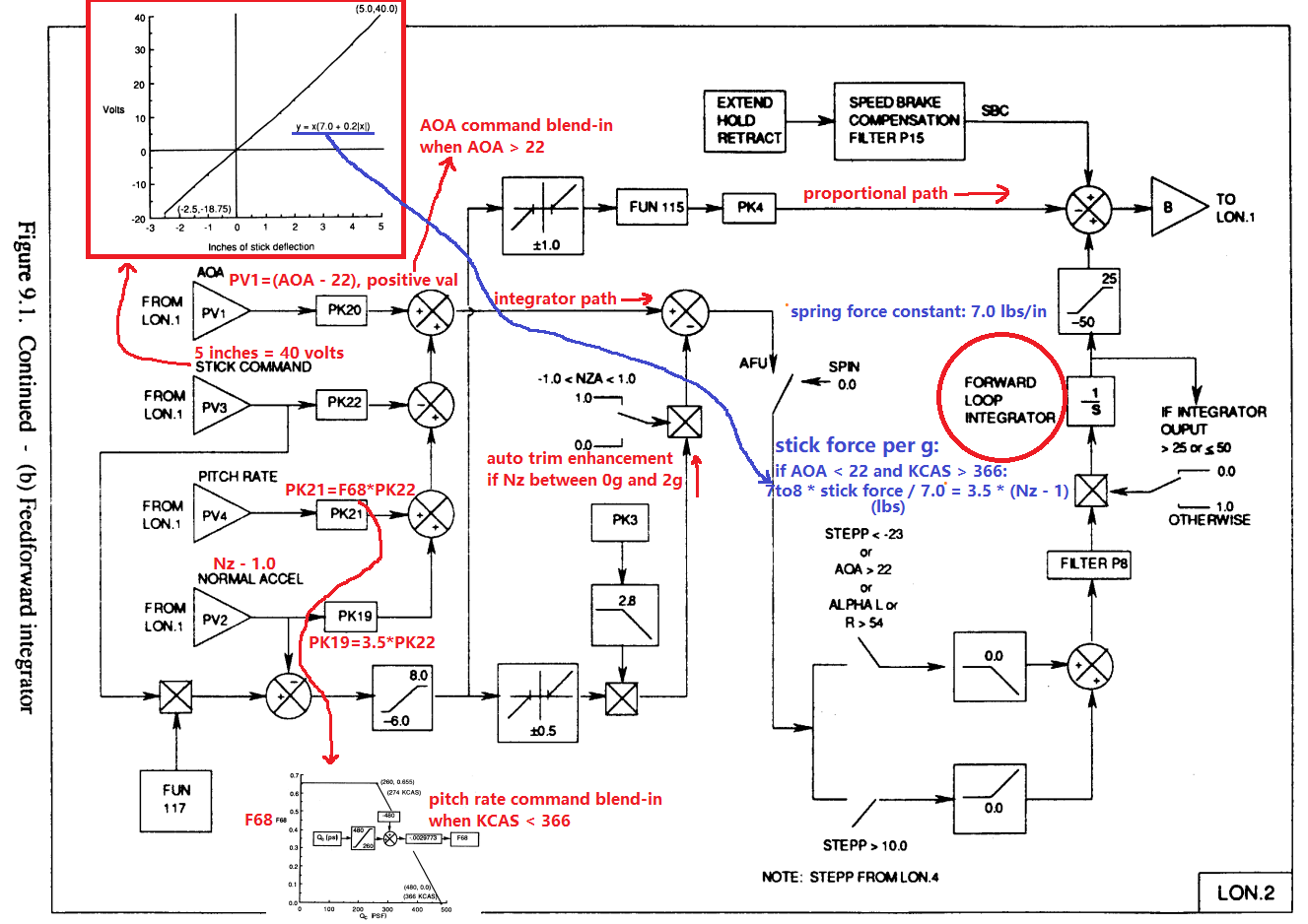
For the exact stick force per g of the Hornet, one can refer to the block diagram (albeit a PROM v10.1 one) from the NASA public paper in order to figure out how many stick input corresponds to the commanded g/pitch-rate/aoa. Specifically look for the inputs of the forward-loop integrator path and ignore all the other paths that are open-loop or belongs to the proportional path, simply because the integrator is responsible of eliminating the error between the stick command and the g/pitch-rate/aoa feedbacks. The F-18 introduces AOA feedback when above 22 degs, and also pitch-rate feedback below 366 KCAS. So as to simplify the matter a bit, we assume a condition of AOA < 22, KCAS > 366, and also the aircraft is not hitting the g-limiter. Then the stick force per g can be inferred by: 7~8 * stick force / 7.0 = 3.5 * (normal load factor - 1) So roughly 3.5 lbs per g. If the airspeed decreases below 366 KCAS, the pitch-rate feedback blends in and the stick force per g increases a bit. If the AOA increases above 22 degs, the AOA feedback blends in and the stick force per g increases significantly. Credits to @Curly Ref https://ntrs.nasa.gov/api/citations/19920024293/downloads/19920024293.pdf
-
Real life Hornet stick force
DummyCatz replied to markturner1960's topic in Controller Questions and Bugs
The longitudinal stick spring force constant (KFS) = 7.0 lbs/in, and the stick has an aft travel range of 5 inches. So you'll get 35 lbs force at 5 inches stick travel. Data source: NASA TM 107601. -
The directional static stability derivative (Cn-beta) of the F-16 reduces significantly at 25 to 30 deg AOA, from positive static stability to neutral and even negative static stability. Hence rudder inputs are strictly prohibited and restricted by the FLCS at high AOA in order to prevent yaw departure, which the F-16 is very susceptible to. Please refer to 'Rudder Authority Limiter' in the FLCS section of dash one.
-
Anyways I've uploaded the evidence and there's two things that can be deducted from the manual: 1. AIM-7 guidance requires PDI waveform, while switching to PDI requires no AMRAAM inflight. 2. Using weapon selector switch to select AMRAAM would return radar PRF to interleaved, thus effectively exits PDI if AIM-7 is inflight.
-
I'm sorry to bring this up but was the issue addressed regarding the AIM-120 and AIM-7 can be guided simultaneously?
-
Hi, Found two control logic bugs. One is related to the stabilators, and the other is related to the rudder. First the stabilators. In my recent deep stall experiences with MPO engaged, I noticed that when the stick is released, the fully-deflected stabs would first return to neutral position upon MPO engagement, which is correct. But then the stabs slowly returned to full nose-down position, as if the pitch integrator was not disconnected, which I considered a bug. In case of a yaw departure and subsequent spin, holding MPO but bot touching the stick is very useful as the differential stabs would help to generate extra yawing moment to negate the spin. If the stabs are fully deflected, we cannot make use of the differential mechanism anymore. The second bug is about the rudder. In a deep stall condition, the rudder would also act to negate any yawing motion, using purely yaw-rate sensor inputs. This is independent of the AOS (angle of sideslip) feedback that could help to increase departure resistance, as elaborated in the dash-1 manual, 'AOS feedback function' and also 'yaw rate limiter' paragraphs in the FLCS section. Holding MPO switch would disconnect the AOS feedback so we only got yaw-rate feedback here. But in DCS, what I noticed is that the rudder is deflected against the yaw half-way through the yaw motion, but then is deflected into the yaw again, as if the AOS feedback is still there and not disabled by MPO. This is highlighted with slow motion in the track. Thanks. F16 deep stall behavior of rudder and diff stab.trk
- 1 reply
-
- 2
-