DummyCatz
-
Posts
191 -
Joined
-
Last visited
Content Type
Profiles
Forums
Events
Everything posted by DummyCatz
-
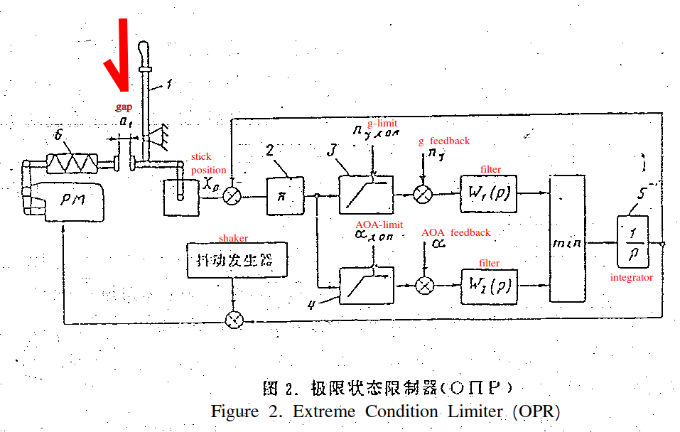
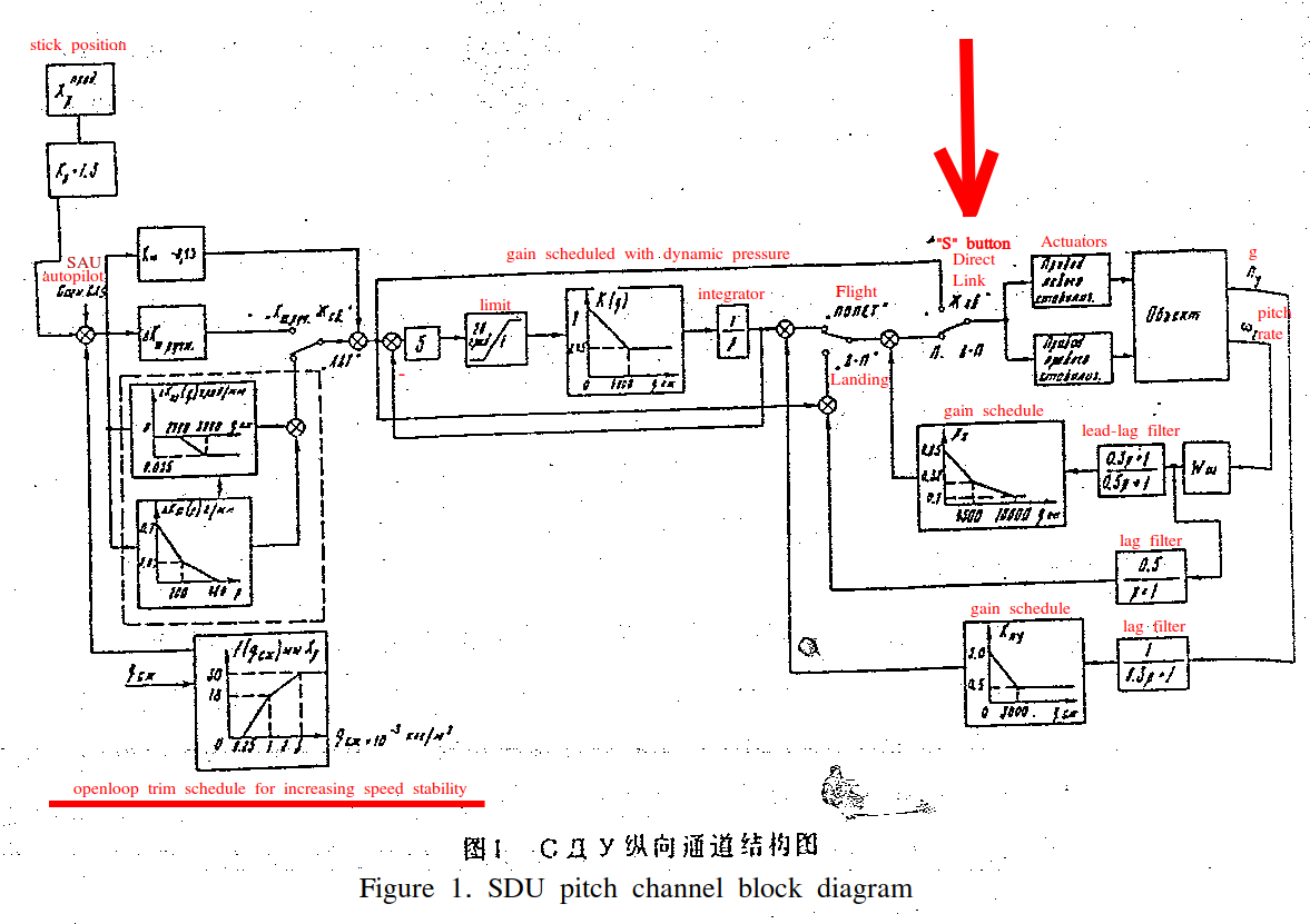
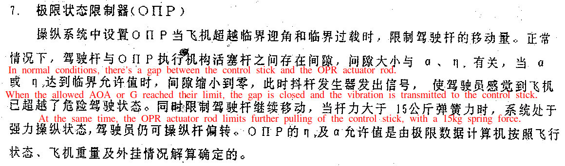
 I'll be quoting a publicly available SDU-10 block diagram to elaborate two discrepancies in the implementation of Su-27 FBW (SDU) control logic. The document is titled as 苏-27飞机电传操纵系统 (Su-27 aircraft fly by wire system), published in 1993 at 第五届飞行控制及操纵学术交流会 (The 5th Flight Control Academic Exchange Conference) held in China. Link below: https://www.zhangqiaokeyan.com/academic-conference-cn_meeting-35806_thesis/020221359205.html The diagram in question is Figure one and Figure two, which is obviously written in Russian and I'll explain in detail later. The first issue is about the aircraft behavior when pressing the 'S' key, which puts the FBW into DIRECT mode. In DCS, there's a noticeable pitch transient when switching the mode back and forth. But it shouldn't, as switching to DIRECT mode only removes a lag filter in the middle portion of the diagram, and the pitch rate and Ny feedback in the right portion of the diagram, which shouldn't be causing any pitch transient if flying straight and steady. In DCS it just looks like the open-loop trim schedule (lower left corner of the diagram) is completely removed when in DIRECT mode, which it shouldn't as it's added to the stick input, without any switches. Track for the first issue below: su27 direct link control test.trk The second issue is about the stick limiter system (OPR) control logic. As shown in the diagram, the integration (1/p) block processes the inputs from the control stick position, AOA and Ny feedback. When AOA or Ny is within safe limits, the feedback to the integrator results in a continuous adjustment of the OPR actuator rod's position, allowing the stick limiter to move along with the stick, with a gap between them. If the stick moves fast enough, it will also hit the rod, as the OPR actuator rod position is integrated at a limited rate. As AOA or Ny approaches its limit, the feedback signals to the integrator decrease the rate of integration. If AOA or Ny reaches the limit, the feedback effectively stops the integration rate, causing the OPR actuator rod to halt in its current position. This creates a physical stop for the control stick, and also the vibration is transmitted to the stick. If AOA or Ny exceeds the limit, the rod moves forward and pushes the stick forward. Now, the issue in DCS is that there's no gap between the stick limiter and the control stick whenever the stick is pulled back a little bit. So the stick will always hit the stop and the vibration will always be transmitted to the stick. IRL it should be moving along the stick with a gap. The gap only closes when the limits are exceeded. Track for the second issue below: su27 stick limiter test.trk
-
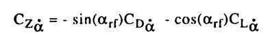
It is clearly Cz (normal force coefficient) in the TsAGI paper, which IS defined in the body Z axis, not wind axes frame. It is not CL (lift coefficient), which is in the wind Z axis. As I already said, Cz = - CL * cos(AOA) - CD * sin(AOA). The paper is using western conventions of flight dynamic symbols when published at AIAA. CL and Cz can be easily differentiable by looking at whether the curve drops at AOA higher than 35 degrees (usually where CLmax happens). For example the NASA F-18 data (https://ntrs.nasa.gov/api/citations/19900019262/downloads/19900019262.pdf) In comparison, the Su-27 (TsAGI data): So my calculation is correct as is. But the first issue depicted in my post is really about whether DCS has implemented dynamic, non steady flow effects such as pitch rate (q) or AOA rate (alpha_dot) contributions to Cz, so that the total Cz is higher than steady wind tunnel data. It’s too long a thread. Would you elaborate?
-
Thanks. Unfortunately DCS Su-27 is not able to attain such g and AOA. Agrees with my previous calculation.
-
high AoA roll when going less than 300kias
DummyCatz replied to 777coletrain's topic in Bugs and Problems
Coming back from 2.9.11.4686. This was originally a bug of being overly prone to entering a deep stall. Back then, performing a high-AOA loaded roll would often result in a yaw departure, making deep stalls very frequent. That bug was subsequently fixed to significantly reduce, if not entirely eliminate, the likelihood of entering a deep stall. While inertia coupling is a real phenomenon that can lead to departures, the FLCS do have some logic to mitigate these effects and enhance sideslip stability (like sideslip feedback that is unique to later FLCS). What do you all feel about the likeliness of entering a deep stall in the latest update? -
Looks like the prompt fix to low speed SEP is nicely done, great job.
-
@NineLine @Yo-Yo Is this sufficient for bug reports, or do I need to create separate threads for the 3 issues above? In summary, the first is for lift/drag or Cz/Nz discrepancies during dynamic pitch maneuvers, the second is for pitch stability and third is for roll-yaw stability. There's more to come with issues in the flight control system, but this is the first step.
-
The 3rd issue is about lateral-directional stability at 30-40° AOA where asymmetric flow separation and asymmetric vortex breakdown happens. Parameters such as Cn_beta_dyn should reflect this, according to the paper. The above track for 1g stall is sufficient to demonstrate this. And this is also a common phenomenon that is missing or ignored in other aircraft such as DCS F-18. The good side is that DCS Su-27 exhibits mild adverse yaw as well as low amplitude roll oscillation at 30-40° AOA, compared to nothing at DCS F-18, but still not enough amplitude, as explained in the paper: I'm also not seeing asymmetric yawing moments that would cause yaw to diverge, so Cn0 and yaw stability (Cn_beta) might need checking too.
-
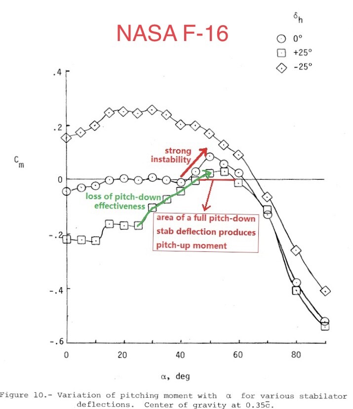
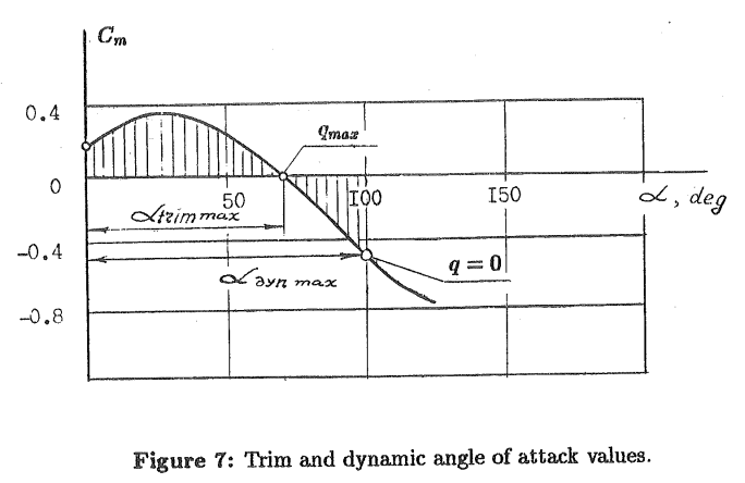
The 2nd issue is about pitching characteristics. Now referencing the Cm curve of Figure 7 from https://arc.aiaa.org/doi/10.2514/6.1993-4737 The aircraft also fails to achieve the expected maximum dynamic angle of attack (α_dyn_max) as depicted in Figure 7 when attempting the Cobra maneuver. Despite varying the center of gravity by adjusting fuel loads, the highest observed angle of attack was approximately 85°, falling short of the anticipated values for such a maneuver. During several 1g stall tests with different center of gravity settings, the maximum sustained angle of attack (α_trim_max) stabilizes around 43-48°, contrary to ~70° in Figure 7. Above approximately 50°, the DCS aircraft demonstrates a clear nose-down pitching moment, with full aft stick. For comparison, a statically stable F-15C with CAS enabled would achieve a maximum sustained angle of attack of around 40-42° with full aft stick, raising questions about the DCS Su-27’s longitudinal static stability. su27 1g stall test.trk Aircraft with relaxed static stability typically exhibit marked instability in the 40-50° angle-of-attack range, driven by elevator stall and forward shift of aerodynamic center. For example the F-16, with Cm curve from NASA TP1538 (https://ntrs.nasa.gov/api/citations/19800005879/downloads/19800005879.pdf) However, the DCS Su-27 does not show noticeable uncommanded pitch-up tendencies during 1g stalls. Releasing the stick promptly reduces the angle of attack, suggesting the presence of positive static stability, contrary to the expected behavior of a relaxed static stability aircraft. If you recall what @Yo-Yo said back then, the static margin of Su-27 should be neutral, rather than positive as of now. What do you think?
-
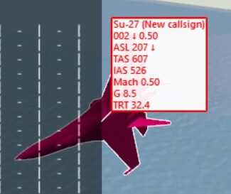
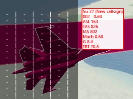
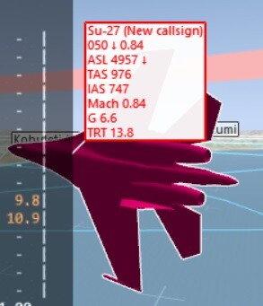
Using this method I performed several tests checking if the G displayed at info bar agrees with my calculation. Firstly the track: su27 cobra test.trk Testing conditions are standard day, with aircraft weight at 20000kg. And here's several screenshot explaining the test points: 1. calculated Nz = 0.5 * 1.225 * 93.7 * 93.7 * 62 * 2.0 / 196200 = 3.4g. Quite close, but this is using steady wind tunnel results and doesn't take pitch rate effects (Czq) and other dynamic effects into account. If using the dynamic Cz from flight test result, which is around 2.8 at 60 deg AOA by counting the pixels in the image, then Nz should be 0.5 * 1.225 * 93.7 * 93.7 * 62 * 2.8 / 196200 = 4.76g, rendering DCS Su-27 significantly underperforming in dynamic pitch maneuvers. 2. calculated Nz (steady flow) = 0.5 * 1.225 * 91.55 * 91.55 * 62 * 2.0 / 196200 = 3.24g. Quite close too, but same issue as above. calculated Nz (dynamic) = 0.5 * 1.225 * 91.55 * 91.55 * 62 * 2.8 / 196200 = 4.54g.
-
Same question asked and I'll just link my answer, over at the F-18 forum where the FM is scheduled for a review and rework.
-
Nevertheless, I can use another source and method to calculate the instantaneous performance, using the wind tunnel and flight tested Cz data, obtained by TsAGI performing a Cobra maneuver, from Figure 6 of https://arc.aiaa.org/doi/10.2514/6.1993-4737 Some basic equations: Total Normal Force = 0.5 * ρ * V^2 * Sref * Cz Nz (normal load factor, or Ny in Russian convention) = Total Normal Force / Weight Note: Cz is not the same as CL in that Cz = - CL * cos(AOA) - CD * sin(AOA). Now dial in the data: Sref = 62m^2 ρ = 1.225 kg/m^3 at sea level, standard day, for example V = 350 km/h = 97.2 m/s, at sea level for example Weight = 20000 kg = 196200 N, for example Cz = -2.0 at 60 deg AOA if only considering steady wind tunnel tests and not considering dynamic pitch rate effects like Cz_q. (See flight test curves) So the resulting normal force = 0.5 × 1.225 × 97.2 × 97.2 × 62 × 2.0 = 717563 N And Nz (russian Ny) = 717563 / 196200 = 3.66g, at 350km/h + 60 deg AOA + sea level, which should be the bare minimum as we're only considering steady flows. Now you're good to perform a Cobra to test it out.
-
So unverifiable. Thanks for confirming.
-
Well the only tool I’m leaning on is the Info Bar (ctrl+y), in which TAS and G are checked against the chart. Tacview was only for illustration purposes in this post. But thanks for mentioning that. And it doesn’t change the testing result and the fact that DCS agrees more with TsAGI data than the manual. Yes but be aware that the manual chart is for a fixed gross weight of 20000kg too, so empty weight wouldn’t matter. Same for F-16CJ charts being checked against our CM.
-
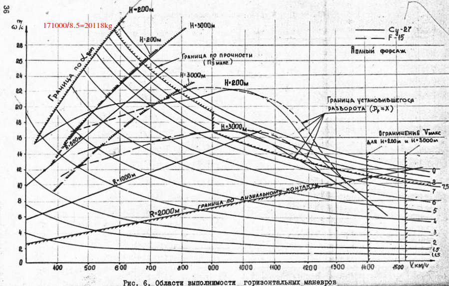
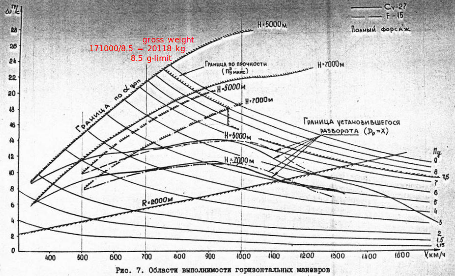
I've completed my testing at 200m and 5000m, standard day (15°C at sea level) with 20% Fuel and 2*R-73 + 2*R-27, so that aircraft weight is around 20000 kg. 1. 200m ITR: above 30deg, checks with TsAGI 200m ITR curve. 2. 200m STR: 8.4g at around 21 deg/s, checks with 200m STR curve. 3. 5000m STR: 6.6g at around 14 deg/s, checks with 5000m STR curve. So looks like it agrees with the TsAGI chart rather than the Su-27SK manual. For example, 5000m sustained Ny is ~7.5g (hits the g-limit) in the manual compared to 6.6g in TsAGI chart and in DCS. As to why ED chose the data from TsAGI instead of the manual is unknown to me.
-
Beside the above proof of lacking adverse yaw implementation, I'd like to point out other missing points as seen in the provided tracks: 1. Lack of wing rock at around 38-42 deg AOA, from page 16 of https://trace.tennessee.edu/utk_gradthes/2312/ This is commonly due to asymmetric flow separation and asymmetric vortex breakdown at those AOA ranges. Parameters such as Cn_beta-dyn should reflect this. Can be calculated from NASA wind tunnel data. FCC OFP v10.7 is able to eliminate the wing rock completely, but here in DCS we don't have it implemented. (See my other threads about FCS OFP v10.7) 2. Lack of falling leaf mode according to page 9 of https://trace.tennessee.edu/utk_gradthes/2372/ Both are about uncommanded oscillatory roll-yaw motions at high AOA, which are currently lacking in DCS. Again the v10.7 flight control is able to mitigate this, but not implemented in DCS. I hope the currently ongoing FM review and rework take the above evidence into consideration.
-
correct as-is The feeling of flying with the F16
DummyCatz replied to mobile83's topic in DCS: F-16C Viper
If you meant the pitch attitude is not stopping at where you want it and the aircraft keeps pitching up or down for some degrees when the stick is released, like a soap, then this is a bug that is being investigated. See: -
While waiting for the recent review and rework for both the flight performance of F-16 and F-18, I think I'll give the Su-27 a late shot. In Su-27, m * Ny max = const = 171000kg for M < 0.85. So the weight for Ny max = 8.5g from those TsAGI turn rate charts would be 171000 / 8.5 = 20118 kg. This would clarify the aircraft weight in those charts from the TsAGI document.
-
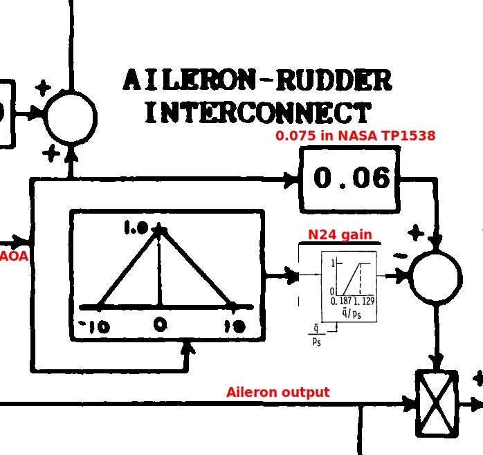
As for whether the ARI commands too much rudder into the roll, one can check if the deflection of rudder agrees with the DFLCS block diagram: Ref 1. Figure 3.3 of DTIC ADA 189675 (https://apps.dtic.mil/sti/citations/ADA189675) Ref 2. Figure 65 of NASA TP 1538 (https://ntrs.nasa.gov/api/citations/19800005879/downloads/19800005879.pdf) From the above references with notes: So when AOA > 10, the rudder deflection can be simplified to 'aileron deflection * AOA * 0.06'. When AOA is between -10 and 10, the 0.06 ARI gain is reduced so that the rudder won't deflect that much at lower AOA, especially at higher speeds. 0.075 is the wrong value as it's outdated.
-
need track replay Viper Flight Model possible error
DummyCatz replied to Cobb's topic in Bugs and Problems
Fixed. FLCS Pure roll inputs cause abnormal pitch up and G. Did the update fix the pitch issue you described? -
unable to reproduce The Viper lost its snap !
DummyCatz replied to hellking's topic in Controller Questions and Bugs
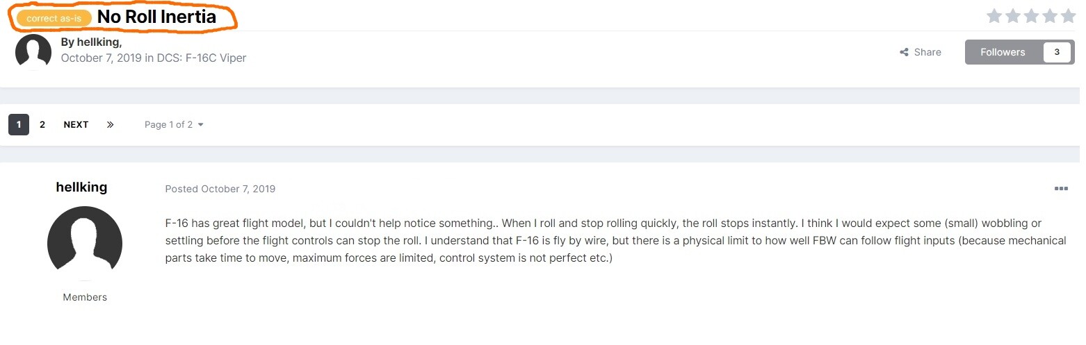
Since we now got the control update, has anyone tested if the roll can be stopped immediately when releasing the stick? I think there was a post somewhere saying that no roll inertia was considered correct as is. The aileron is supposed to deflect to the opposite direction to stop the roll when releasing the stick.
-
need track replay Viper Flight Model possible error
DummyCatz replied to Cobb's topic in Bugs and Problems
Related pitch behavior issues: 1. pitch down when rolling to the left 2. pitch up when roll-out -
investigating Hornet's Slow-State Energy Bleed?
DummyCatz replied to wilbur81's topic in DCS: F/A-18C
It's a good question on what kind of realism do we seek. This thread is only about whether the flight performance agrees with publicly available data, which are scarce at best and limited to a few public NASA papers and GAO reports. It surely doesn't suggest that we should seek for a real life 1:1 copy, or even we know that the remaining large portion of non-public part is accurate at all. These scarce public data points aren't classified specs or obscure details, but rather fundamental performance (SEP) characteristics. I believe replicating these accurately should be the bare minimum for a module that prides itself on FM realism and sold for 80 bucks. Still, the ongoing extensive FM review and rework suggests that ED are open to enhancing accuracy when presented with compelling evidence, even if perfect replication isn't the goal. -
You can check your actual trim position by the tiny '-' symbol in the control indicators (ctrl + enter). If you take-off with the symbol not at neutral position in FLAPS AUTO mode, you may end up with a continuous pull because this trim bias is persistent in the FCS, until you switch the FLAPS down and up again. The following are my in-game observations and might not related to RL values: There seems to be two independent trim values in DCS F18. One is the actual trim position indicated by the tiny '-' symbol and corresponds to your reference/trim AOA. The other is the pitch integrator or elevator position when WOW which is displayed at the FCS page. Both are affected by the trim button and can be accumulated independently, with different value ranges. With FLAPS at HALF or FULL, the actual trim position is limited to positive values and act like a bias added to the pitch integrator. The full range of this trim function is like 0-12 deg, which initially corresponds to 6-18 deg NU elevator position. I said initially because once you trim past 18 deg NU, the actual trim reaches its maximum position, but the elevator will still go all the way to 24 deg NU. Now if you trim forward, the elevator position reduces but the '-' symbol moves upwards at the same time, like the trim doesn't wait for the elevator to be reduced below 18 deg NU. So there's no 1 to 1 relationship between the elevator position and the actual trim position, at least in-game. (I'm not sure if its a correct behavior.) When pressing the T/O Trim button, this trim position is initiated to half way of the full trim range (around 6 deg), and corresponds to 8 deg reference/trim AOA. If you have not trimmed past 18 deg NU or 0 deg ND elevator, the trim position also corresponds to 12 deg NU elevator.
-
New FM, pitch oscillations on supersonic speed
DummyCatz replied to Blackfyre's topic in Bugs and Problems
Significant overshoot like this is a very unwanted characteristic and can result in low flying quality ratings due to insufficient damping of the short period pitch oscillation according to MIL-STD-1797A (https://www.scribd.com/document/49403406/MIL-STD-1797 with DISTRIBUTION STATEMENT A: Approved for public release; distribution is unlimited). If it's true then this is a design flaw of the FCS, that Level 1 or even Level 2 rating cannot be guaranteed. -
investigating Hornet's Slow-State Energy Bleed?
DummyCatz replied to wilbur81's topic in DCS: F/A-18C
There have been 1g SEP (acceleration) issues that can of course be investigated together:

.png.d7b68c0e331cad5a2c29d1b04c65306a.png)