
Aronis
-
Posts
248 -
Joined
-
Last visited
Content Type
Profiles
Forums
Events
Everything posted by Aronis
-
 Did you make a video oh exactly how you did it? LOL. Mike
 -
Using VC to do this is a back burner project, been working on switch boxes. I just move the KB at start of mission, not a big deal. It is too bad that modifying the Lua screws with the On Line game play. Oh well, minor issue. Mike
-
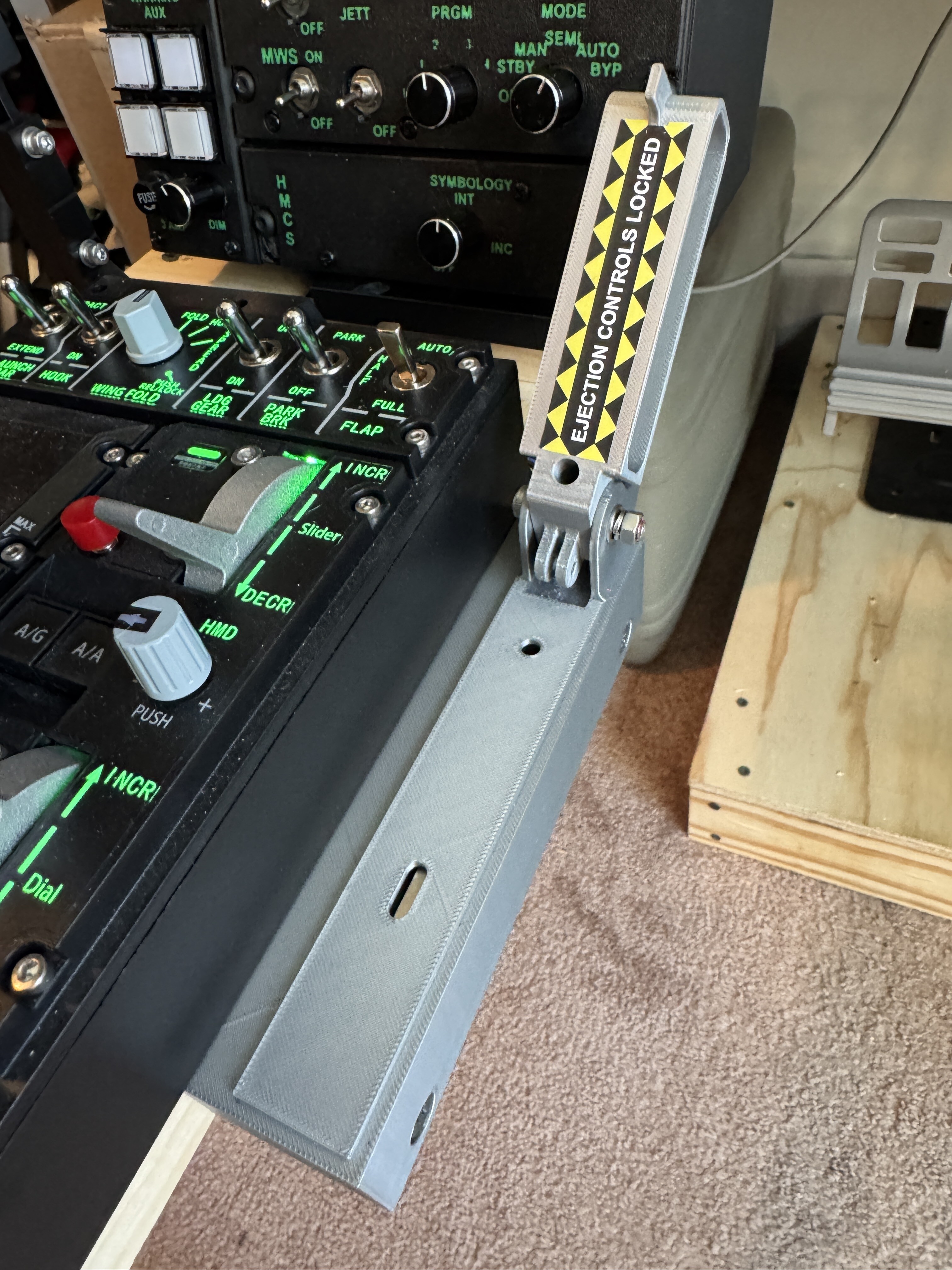
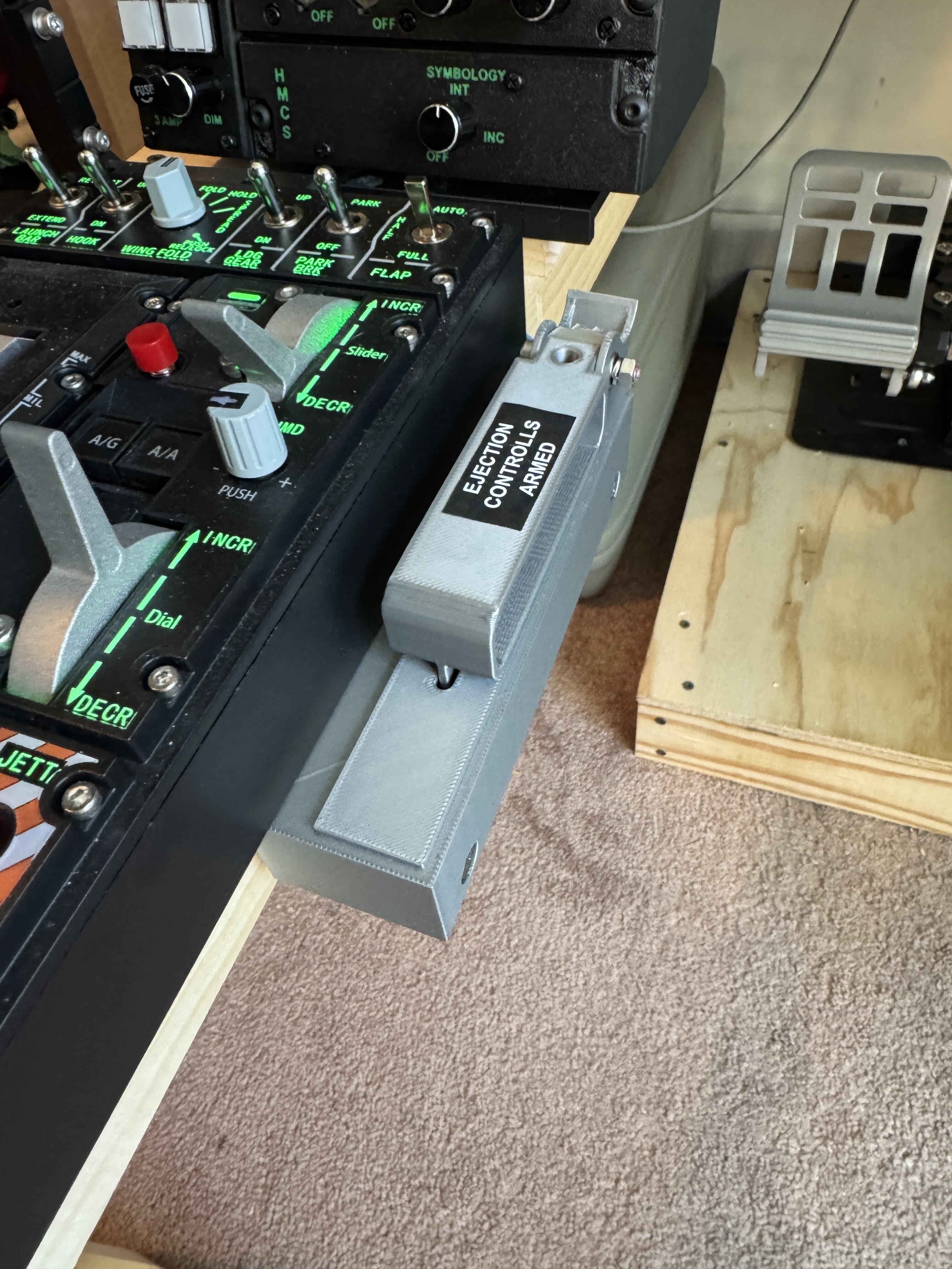
F-16C Ejection seat arming handle
Aronis replied to Nightstorm's topic in Utility/Program Mods for DCS World
works LOL. Now canopy latch spider and switch I was just going to use one of the spare switches that I freed up on the Throttle base, but there is no in game coding for that switch and I don't want grief if I try to fly on line. Mike
-
F-16C Ejection seat arming handle
Aronis replied to Nightstorm's topic in Utility/Program Mods for DCS World
I tried to code from Bort but it did not work. never mind, I got it working Mike -
F-16C Ejection seat arming handle
Aronis replied to Nightstorm's topic in Utility/Program Mods for DCS World
If you make the modification to allow for coding the Ejection Seat Arming Handle, does that create an issue playing on an online server??? I know modifying the location of your KneeBoard does. Mike -
I wanted to but the space it too tight. Would have to move too much stuff. LOL. Mike
-
Amazing to see such great workmanship from a home DIY person. I have been tempted to buy a laser etcher, and cutter, perhaps some day. This is a hobby you can do at any age, as opposed to cabinet making, or auto work, as you get older lifting heavy <profanity> becomes a problem. I've DIY many project from pulling engines to installing in-ground pools, roofing a house to finishing basements, installing whole house generators to building PC's. This kind of DIY is fun and not physically taxing, until you have to crawl onto the floor to reach behind the PC to plug in something LOL. Mike
-
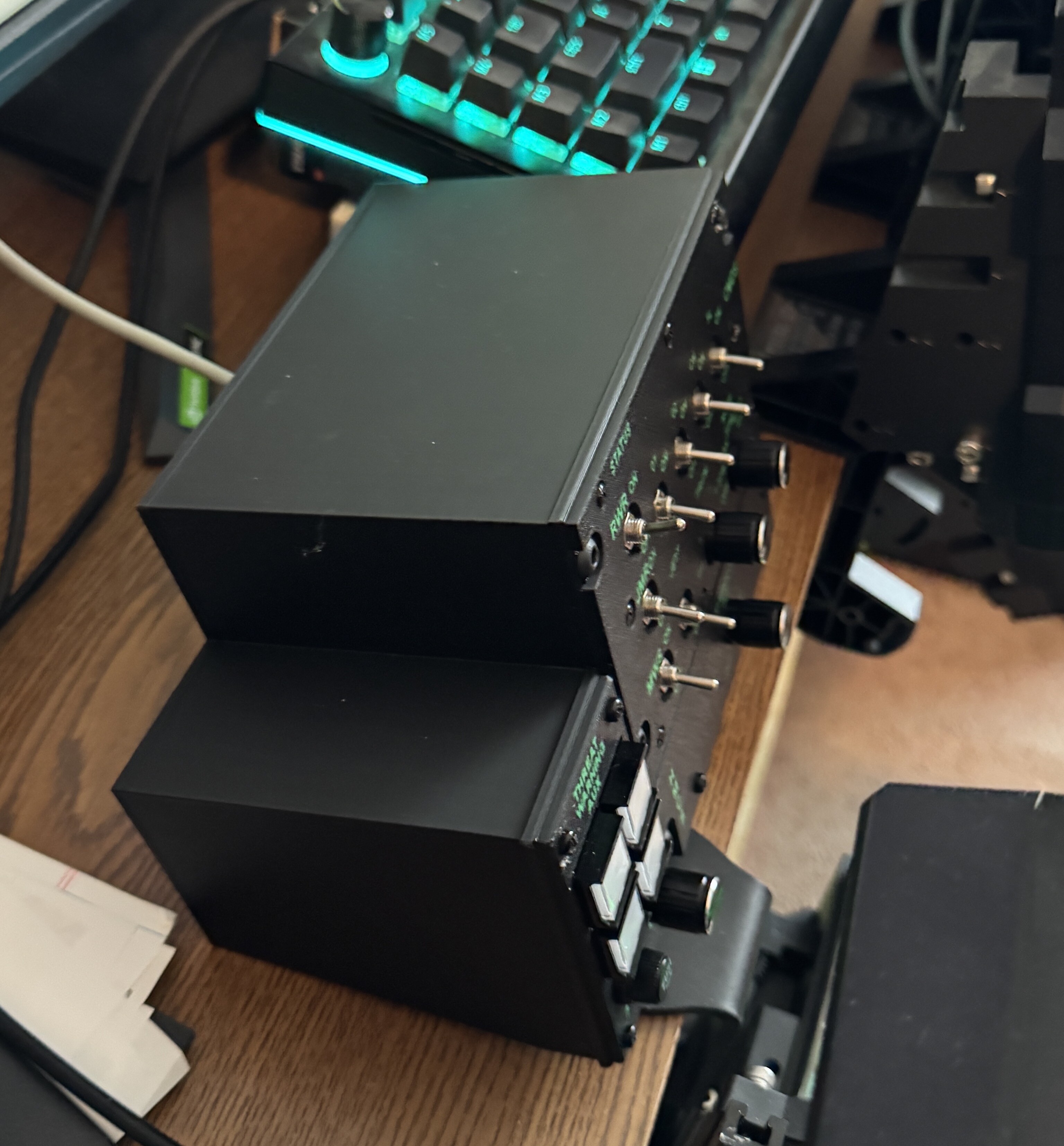
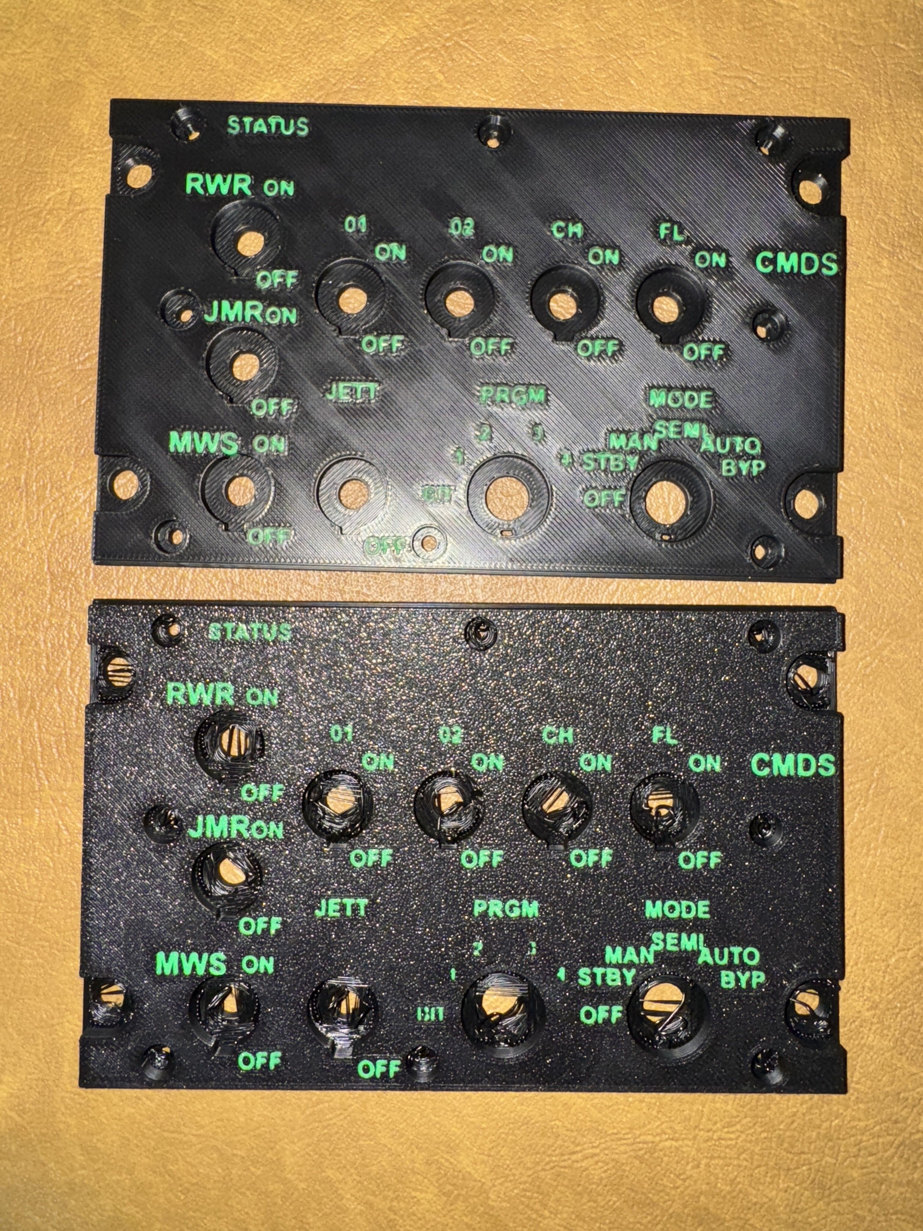
Got the lights working. I removed the resister in series (just like I did on the other box) and now working on the Coding for the game. After some fiddling got to a point to test in game and the switches work correctly for the RWR controls, but the lights do not, yet work correctly. I have to figure out the code, perhaps an error. I need some dedicated time to work on it. Once that box is working, I want to move on to remaking the other two. Mike
-
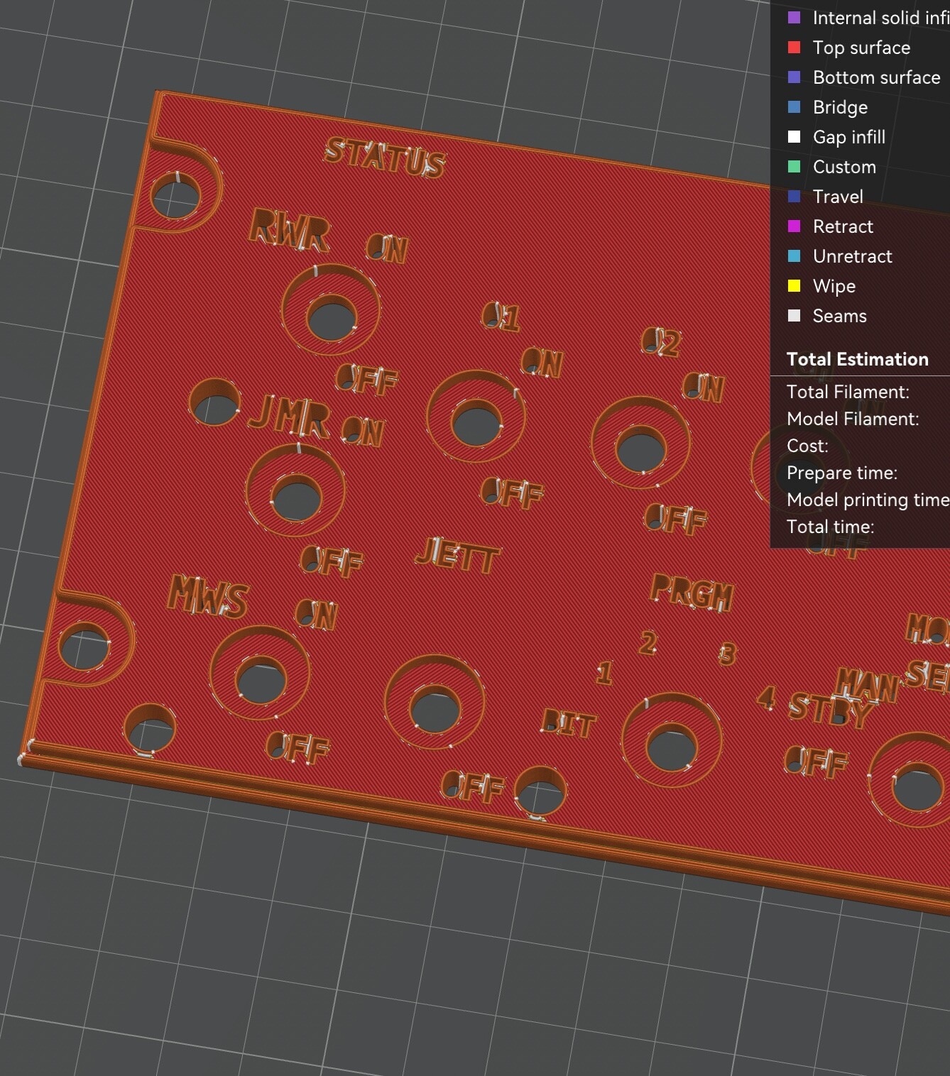
I got the smooth plate for the Bambu printer and I am interested in reprinting the panel with face down on the smooth plate to see the effect. Mike
-
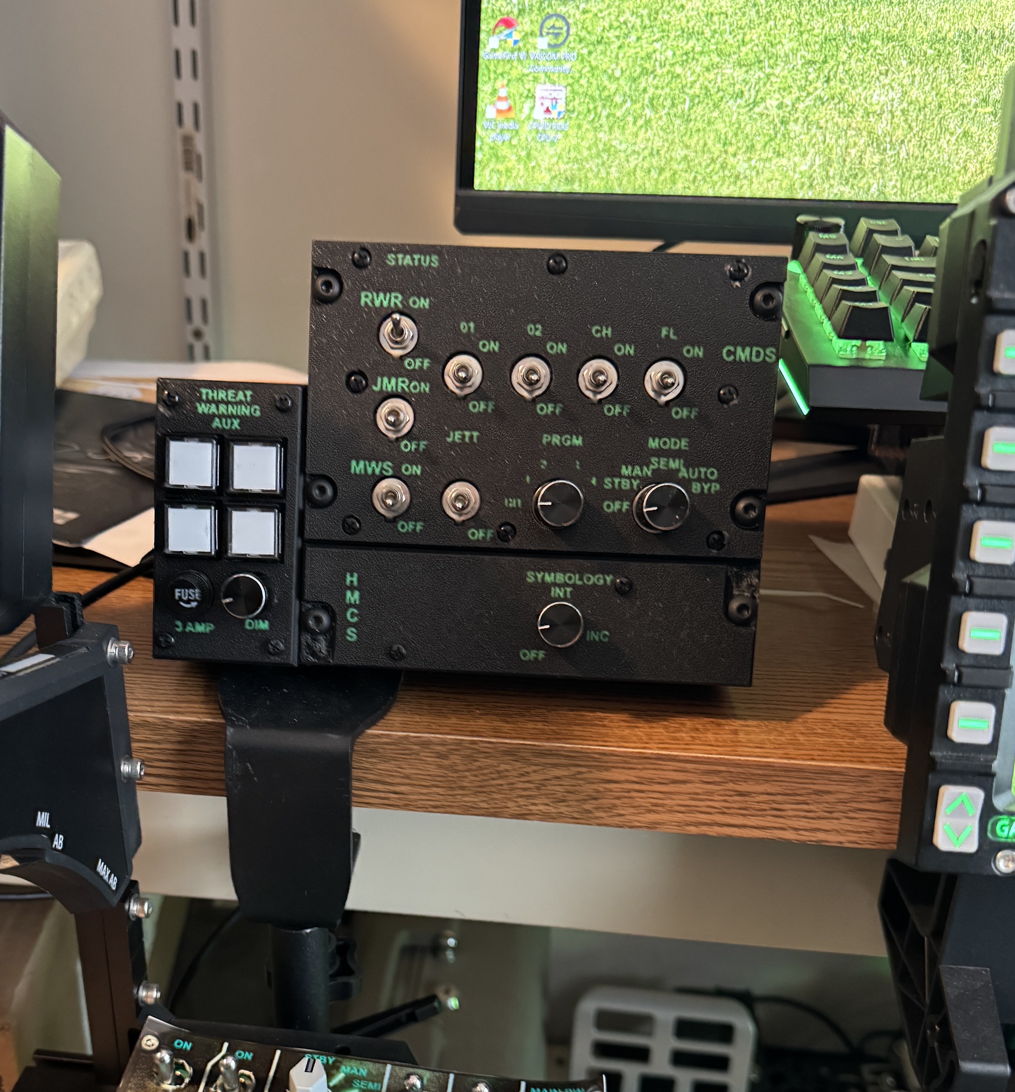
Final Version. and it works. I just have to work out the issue with the lighted switches. When I first connected to the Arduino I had odd flashing of two of the switches and a bad burning smell. I did not burn out the Arduino, but just disconnected the light part of the switches to work the function of the rest of the panel. Mike Maybe some day I figure out little number panels for the Status row. Or just look up at the screen LOL. Mike
-
Very nice. I guess I'll have to print the correct knobs too LOL. Yes, I have a .2mm nozzle on order. Mike
-
method for making panel I used FreeCad. Start with new project. If there are errors here I apologize. I did not take notes as I went until NOW, after messing around with several different techniques. I am sure there are other ways to get to where I ended up. in Part Design WB, Create Body (Body001) the same WB, Create Sketch, (Sketch001) start with panel first sketch for basic panel shape including location of any holes you want to great, then use Pad to make the panel and choose the thickness, I used 3 mm. The location of the holes in the sketch will be needed to reference when you make the next panel so they line up. More on that later (you can copy the sketch and make a new sketch from it) As you go you can rename the different items such as change PAD001 to “Top Panel” or similar to keep track. In this I keep it as PAD001 for reference below. In Draft WB create the ShapeStrings for the text, each word or letter needs its own ShapeString and you need to choose the size of the text and the proper font, and then located them on in spots references by your Sketch. Leave the Sketch001 turned on so you can see where stuff will go.. I tried ‘grouping’ the Shapestrings but have to revisit that, I just leave them in the Tree where the are and reference them. You will need to reference them several times and if you want to change the Shapestrings for Font or Size you have to start over from the step below (adding graphic cutouts). Now make a simple copy of the first Pad001 (will be at bottom of tree) and will be called PAD002. Change to Part Design WB, click on the new Pad002 to highlight it, then use “Create Body” and a body will be made using this PAD002, with in Body002 there will be “BaseFeature” which is the new panel you can work on more. Change to Part WB, so you can add Fillets to the edges of the Panel. Make Body002 the Active Body by right clicking and checking the box “Active Body” Highlight “BaseFeature” by clicking on it, then hit the Fillet button on toolbar. Choose the edges you want to Fillet, pick first, hold Command key, then once they are all highlighted (green color usually), click ok. (large tree’s will make calculations take time so wait it out) This will create “Fillet001” at bottom of Tree. You can rename if you want. Next to add the Text (ShapeStrings) Go back up to the location in the Tree where your ShapeStrings are, click the first, hold Command and click the rest. enter Draft WB, select each of the graphics (click first, hold Command (CTRL on Windows) and click each Shapestring, and use “Draft to Sketch” command to make Sketch with graphics, will be at bottom of tree, call Sketch002. Change to Part Design WB, highlight the “Fillet001” and use “Create Body” command and a new body will be made from the Fillet with a “BaseFeature” Change to Part WB, and drag the Sketch002 onto the “BaseFeature” and that sketch will become associate with that body. Change to the Part Design WB, make sure that “Body” is the “Active Body” and then highlight the Sketch by clicking on it, then use the “Pocket Command” and the Text will be cut into the panel and that will be called “Pocket001.” Now go back and make you Bottom Panel as above. BUT you will need to TRANSFORM the new plate and adjust it’s Z coordinates so the plates sit one on top of the other. Once you have two overlapping plates with the holes and text correct, you will need to make the text Fill Ins and then the Holes in the Text Fill ins below. Back to Part Design WB, Create new Body, will be at bottom of tree. Go to Draft WB, select your graphics ShapeStrings, uses Draft to Sketch command again, creates Sketch, will be at bottom of tree. Go to Part WB, drag sketch onto the Body, will associate the Graphics containing sketch to that new body. Still in Part WB, highlight that new sketch and use the Extrude Command, I chose 6 mm since the two panels are 3 mm thick each, and I want to make the Fill In text 6 mm total. Look on the Edge by rotating you parts and adjust each by using Transform to make sure things line up in the proper Z plane. Next make the fill ins for the text holes. This involves using the Pocket command but pocketing 6 mm into a 7 mm PAD and then Cutting that extra MM off, leaving the Text Hole Fill ins in free space. This is a bit tricky. Part Design WB, go to top of the tree, high light the main name (otherwise when you do the next step you will get it trying to create a new body with what ever element you have currently highlighted, not necessarily the “Active Body”, then create new body, will be at bottom of Tree. In that new body, create a sketch, make a box larger than your overall panels. Then Pad that to make a 7 mm Pad, will in Part Design WB. Go to Draft WB, select your graphic ShapeStrings, “Draft to Sketch” Command, new sketch at bottom of Tree. Go to Part Design WB, drag that new Sketch onto the “Body” and it will be associated with that body and new Pad. Then use the Pocket Command and make the Pocket 6mm into the 7 mm Pad. “Bodyxxx” Lost track of the numbers, as I type this my document has many bodies already, so my ‘new bodies’ are numbered differently than in this work flow assuming you started with a fresh project. A few notes, this new pad may end up being in a different Z plane position than your other panels, and the Pocket will be made from the Bottom to the Top, it’s just where the “Sketch” exists relative to the Pad. No problem. After creating the Pocket, just rotate your new big Pad to see the holes. Now to cut off the extra 1 mm part. Part WB, make sure nothing is “Active Body” use the Cube button to make a cube, then adjust that cube into a 1mm thick slab which is larger than your overall panel size in the X Y plane, you will then have to move it into position relative to the other Panel you want to cut. Align it with that new slicing slab overlapping with the PAD you want to cut at the Z level of the Extra Un-pocketted part of the PAD. Part WB, Under the BodyXXX highlight the “Pocket” and Make a copy. Will be at the bottom of the Tree, PocketXYZ. Highlight the PocketXYX, command click the Cube (cutting slab), use the “Slice Apart” command under “Split” and this will create a group of sliced parts. Click to hide each slice, usually the two top slices are the ones you don’t want and you will reveal your Text Holes to fill your Extruded Text. Under the Exploded Slice, high light the slices you want and use Union Command, will make a “Fusion” under the group Exploded Slice. Make Simple Copy of the Fusion and it will be at the bottom of the tree. Now adjust Z plane position and all the parts should line up. Select each of the four components, click one command click the rest and Export as a 3MF Import into your favorite Slicer and print it. Print with the TEXT filament as first Filament so the text will be readable. I put the object face down so the print would have a texted surface. I tried both ways and the top up creates a cross slash on the surface. The results were ok, but I like the texture better. Mike I'll test out the Ironing, I had read about that. I am Printing the HMCS panel now. Had to work it over to change the Fonts. Arial Bold seams to work. Each panel had to be adjusted after changing the font AND correction a typo (Left out the M in Symbology) LOL. I am not buying a laser etcher also. That gets GREAT results I know, the stuff people make is Simply Amazing, but this is more than Good Enough for me. Very happy with the outcome. The printer was $1700. Enough for this hobby. Mike
-
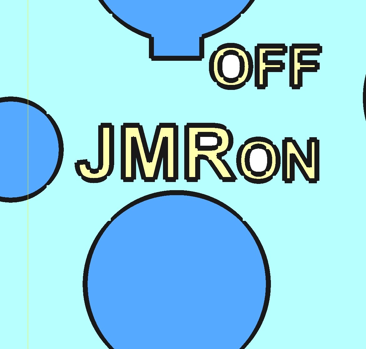
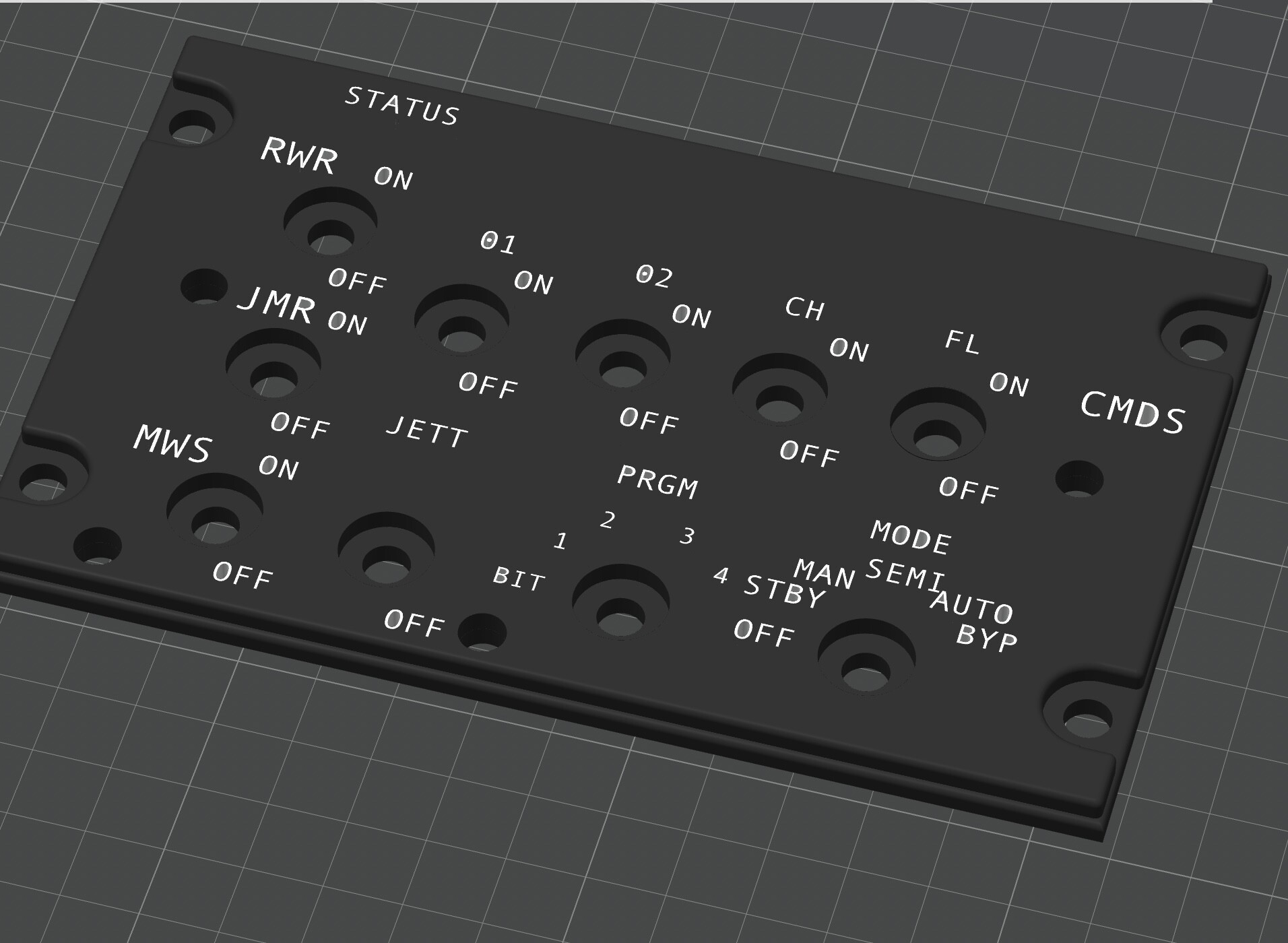
nullTwo things I learned, which turned out to be key. 1. pick the best font, wide BOLD font (Arial Bold) and 2. print the letters First then the black. Goal is to print with Clear Filament with the first slice using the green filament and see if it is translucent enough. But without back lighting I think it's good enough. I did not design all the graphics into it. I have yet to figure out that one as it requires more tedious work to draw the graphics. I have a draft done, but did not implement it last night. Mike
-
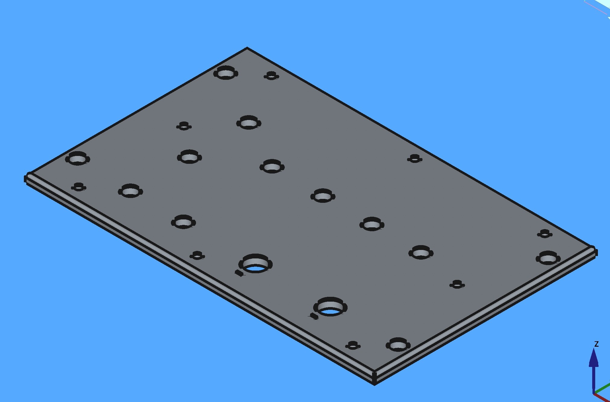
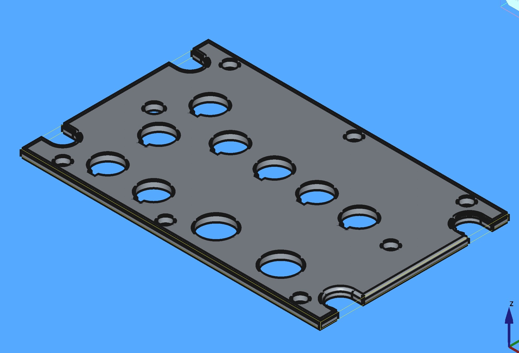
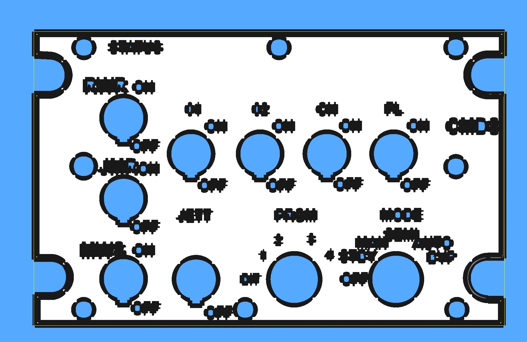
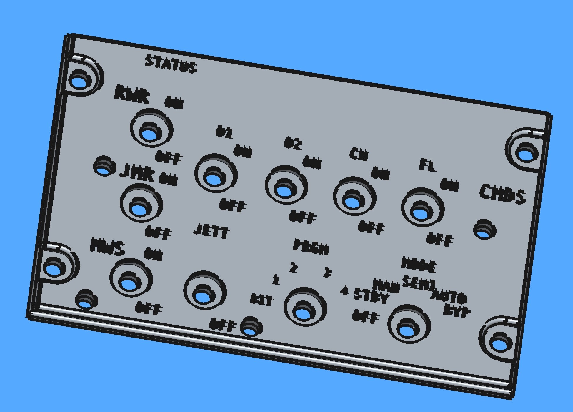
nullBottom plate nullTop Plate nullTop Plate with letters cut out nulltext fill in object, holes in O and R need one more element. nullHoles Filled.
-
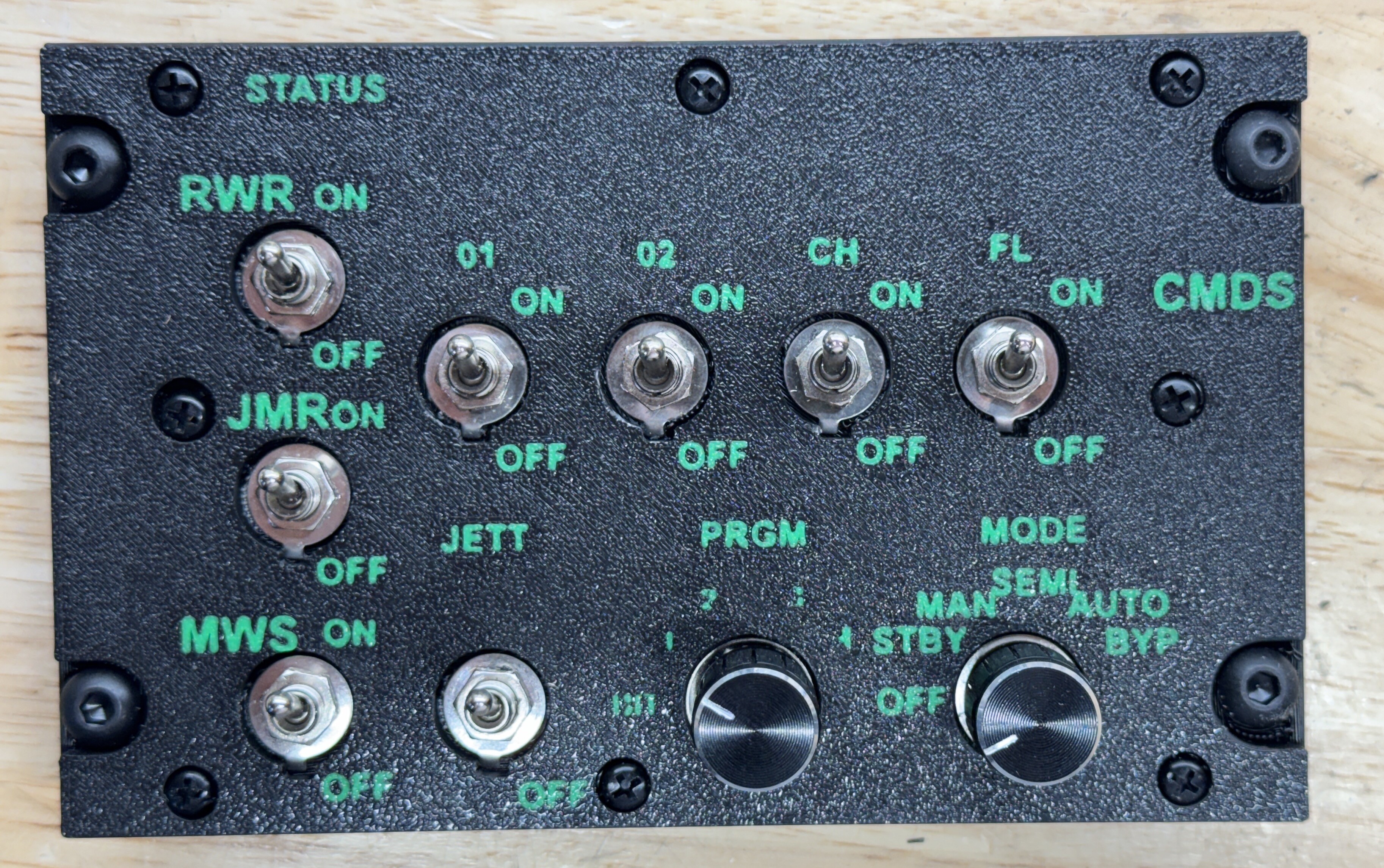
I bought a 3D printer last week with the hopes of making decent panels. There is a learning curve on the software and the device. I started this project last week (Sunday) and worked at learning the software. I am using FreeCad because, you know, its free. I got a Bambu Labs X1C with the AMS (multi color) and started actual prints on Friday afternoon after unboxing and setting it up. LSS here is my CMDS panel. I will re-do with clear filament but that has its own learning curve. You have to dry the spool of filament for 8 hours first LOL.
-
I had to figure out how to fill the holes left by the Text. And did. Printing the first test now, and it's almost done. The printer came with Green and Black. I bought several rolls of black and clear, but the clear requires 8 hours of Drying in the printer before I can use it, so I printed just the CMS panel in black and green. It's almost done, but looks pretty good so far. This is the final package to print tomorrow. Mike
-
almost....:) Mike
-
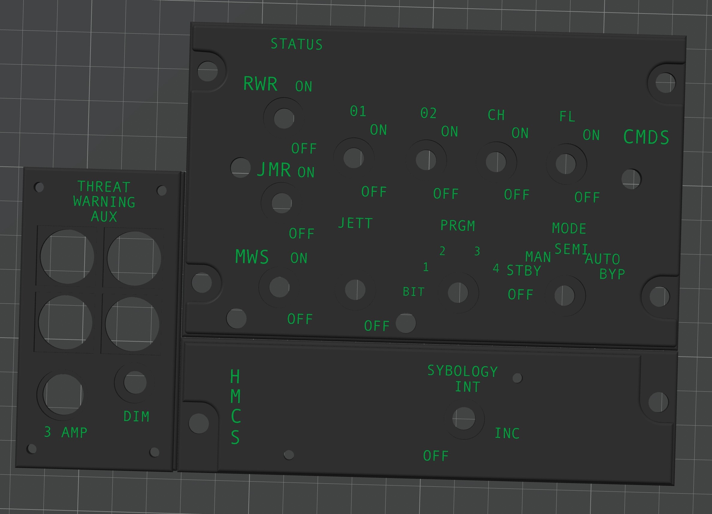
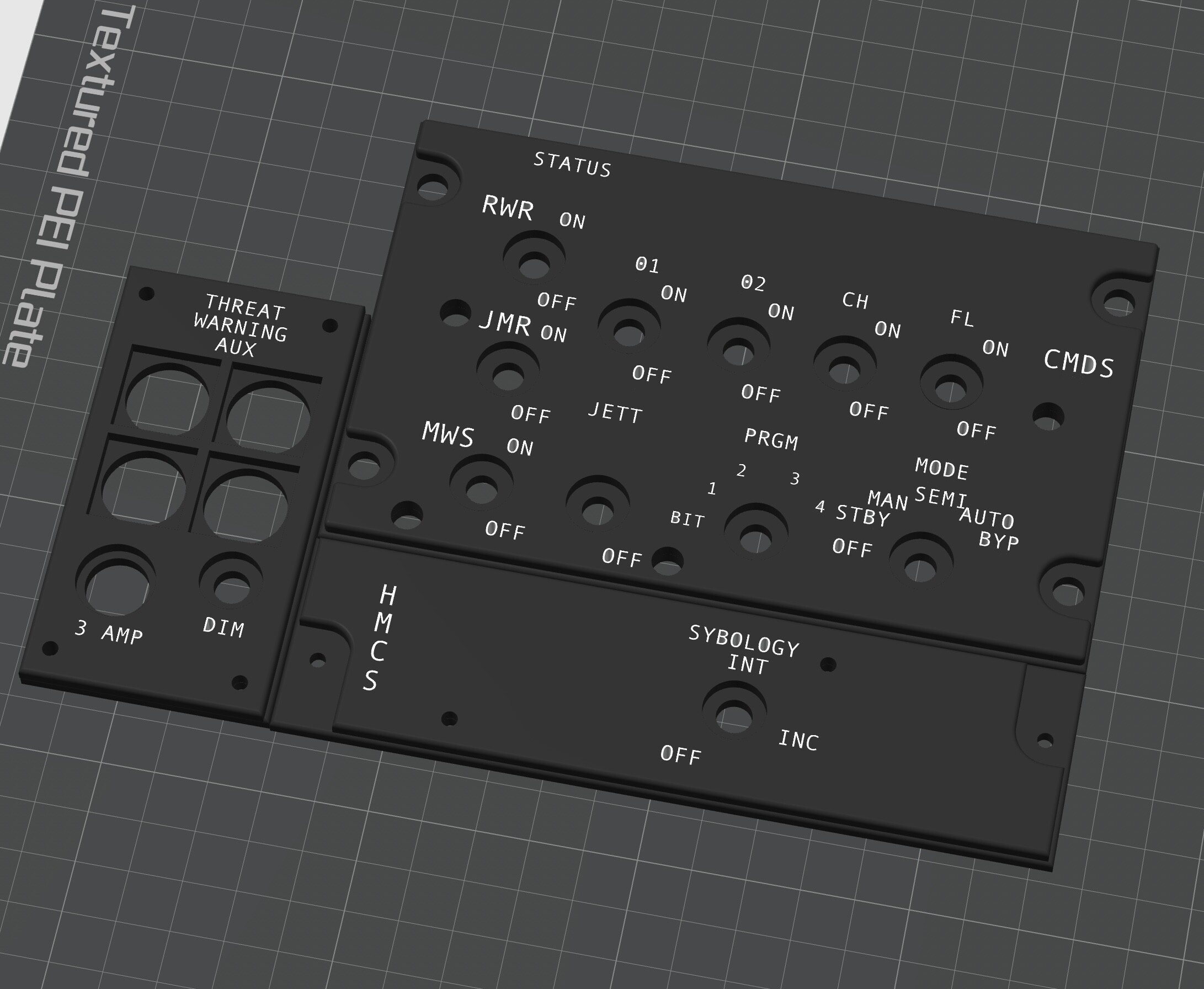
nullNext 3D print. Mike
-
Just finished the panel. Ready to 3d print. Mike
-
Agreed. I did not even take a PHOTO of inside this particular BOX, it's a wiring NIGHTMARE, not a pretty thing, never mind posting a PHOTO of it. So no PHOTO. When I open the box again, I am sure I will be again repulsed by the appearance, but again, its a prototype not a finished product. Mike
-
yes, they are ugly but they work. LOL. Mike
-
Out with the old....3d printer arrives Friday. Mike
-
No1sonuk, The length of the wires is all about the same, however this is a VERY messy build, I was rushing it too much. That's a prototype anyway, I am going to open the box and check the solder on the connections. The Capacitor is a great idea if the joint is not the issue. I have spent a few hours this week learning FreeCad and so far I have designed these. First is the display on Freecad, and the second is the 'preview' on Bambu Studio. I still need to extrude the letters to add them to the model and print in two colors. the other panels are very low tech. Mikenull null null
-
I finally had time to fly a mission and do a shake down on my second switch panel. One of the three position switches (assigned to the wing/tail position light) is flickering back and forth from bright to dim when it is in the 'off' center position. I suspect its just a ground wire issue and have to take the switch box apart. Just thought I'd ask for input to confirm? In game workaround, put physical switch up and turn switch to off in game, so flew the mission, got shot down LOL. The switch boxes I built are pretty much prototyping. Its fun just building this stuff, so of course I bought a 3d printer. Let the madness begin. Mike
-
Got it all sorted out. I was able to get a better rotary switch and convert it to a pot by adding some resistors, and then programmed a second Arduino Uno as a test base, I got it kinda working, but if I rotated the switch to far clockwise direction it got wonky. So I then figured out how to test the pot/switch with a Sketch that shows the values at each setting, and figured out I had it wired off by one pin. Once I got the switch working and figured out the error, I was able to plug the new stitch back into the main Arduino Mega and everything works properly. In the code: DcsBios::AnalogMultiPos insKnb("INS_KNB", PIN, STEPS); I found that I needed the number of Steps in the code to be set to 8 even though the in-game simulated switch setup was only for 7 positions. I think if I move my positive lead back one pin and remove a resistor I can set that Steps to 7, but I don't think it makes a difference as the extra switch position does not get used anyway. I still do not understand why using the 8 digital inputs for switches would let the In Game image of the switch move correctly, yet the iNS was not setting up correctly in the simulator. It's just odd. Perhaps I'll try just for kicks and giggles using one of the better rotary switches I bought. Some times good enough is not good enough, and you just have to know why. I tested start up 4 times and the INS was proper each time including showing the flight path marker correctly. Mike