Bacab
-
Posts
211 -
Joined
-
Last visited
Content Type
Profiles
Forums
Events
Everything posted by Bacab
-
I have just tested it. Setting the alarm state to green do nothing for artillery units. On SCUD it causes them to actually get ready to depart. Setting the alarm state to red actually achieves what I am trying to do for SCUD and part of what I am trying to do for artillery: the artillery unit actually deploys but in the absence of a target the gun stays horizontal whereas by setting a "fire at point" and then deactivating the AI the unit actually points upward its gun; showing a more ready state.
-
Thank you very much ! It works as intended and allows me to strike threatening SCUD pointing at the sky or artillery positions that look like they are ready to fire. It's a small thing but with that I can reproduce targets as they are depicted on IRL reconnaissance pictures that I have.
-
Hi everyone, I have made several missions where I use artillery units (with L118 Light artillery guns or SCUD TEL for instance) as targets. These units spawn in a towed position, ready to move, but since I want to depict units ready to fire I would rather have them in a deployed position. Is there a way to command them to deploy in the ME ? The only way I have found until now is to order them to fire at a point continuously (when they are done with the "fire at point" task they return to there towed position) but then the endless stream of gun fire log is cluttering my debriefing window + they are more easily spotted during the mission. So the question is, is there another way ? Thank you in advance for your answer.
-
You are missing the point: the issue is not to say that it doesn't work in Loft or in Offset, just to say that Jester does not automatically set the VIP upon overflying it even if you press the bomb button as a pilot (even if you have told him the correct offset through the bombing calculator). When overflying the VIP you have to take the role of WSO, press the "Freeze Signal and Target Insert Signal buttons" yourself and then upon returning to the pilot position you will be guided to the release point and everything will work as intended.
-
I am sorry to insist but I have the same issue : upon overflying the VIP the manual tells us "the WSO simultaneously presses the Freeze Signal and Target Insert Signal buttons on the Cursor Control Panel; doing so initiates INS target tracking." From your answer I guess Jester should do those two actions when I press the bomb button as a pilot, however I think this is not the case currently. Indeed, when overflying the VIP, when I press the bomb button, the flight director still sends me to my next waypoint, not to the offset I told Jester to set. I have done a track although I think opening the bombing calculator in flight seems to brake it. EDIT : If you manually do the pressing of the Freeze signal and Target insert as the WSO when overflying the VIP, then it works fine. F-4E_Offset_bombing_no_luck_v2.trk
-

Need help exporting the magnetic heading using DCS-Bios
Bacab replied to Bacab's topic in Home Cockpits
This is a good solution that I will try on the F-16, F-18 and AV-8. I will try it as soon as my build is finish : I have just eradicated the last bug from the software and I am in the process of finalising the box that contains all my flight instruments. Once that is done I will try the solution you offer. On a side note, just in case someone is interested in building a compass for DCS Bios : - A-10C: export the HSI heading, values are reversed so 360° to 180° is 0 to 32 768. Displays the magnetic heading - AJS-37: export the CI heading, the exported values are in degrees. Displays the true heading - F-86: export the heading value, the exported values are in degrees. Displays the magnetic heading -L-39: export the HSI heading, values are NOT reversed so 360° to 180° is 65535 to 32 768. Displays the true heading -M2000C: export the HSI heading, values are NOT reversed so 360° to 180° is 65535 to 32 768. Displays the magnetic heading -MiG-21: export the HSI heading, values are reversed so 360° to 180° is 0 to 32 768. Displays the true heading -All WWII aircrafts: export the DI GAUGE (directional gyro) instead of the compass. Their compass are too wobbly (and not accurate at start so you can't rely on them to deduce the magnetic variation) so it will lead to erratic, very fast movements, of the stepper motor which the stepper does not like at all ! Though it is not a direct reading of the magnetic heading it is generally synced to the magnetic heading at start and before all navigation and their output is a lot more stable. All values are between 0 and 65535 but I have not played enough with them to sort if they are reversed or not (they don't seem to be reversed though). -UH-1H: export the GMC heading, values are NOT reversed so 360° to 180° is 0 to 32 768. Displays the magnetic heading (if manually sync) Thank you for your help. -
Need help exporting the magnetic heading using DCS-Bios
Bacab replied to Bacab's topic in Home Cockpits
Thank you very much for the help. I would have preferred the heading from the EHSI but i understand from what I read it currently behaves like a screen and it can't be exported as a gauge. I will test the whole thing today and keep you updated. PS: I have seen your talk on git hub. I can tell you the F-5 compass is also reversed. However it is very easy to solve, so not a big deal. -
Need help exporting the magnetic heading using DCS-Bios
Bacab replied to Bacab's topic in Home Cockpits
Indeed ! thank you very much ! -
Need help exporting the magnetic heading using DCS-Bios
Bacab replied to Bacab's topic in Home Cockpits
Thank you for your answer. If they are no solution, I'll wait. -
Need help exporting the magnetic heading using DCS-Bios
Bacab replied to Bacab's topic in Home Cockpits
Thank you for your answer but I am not sure you understand what I am trying to do. Since DCS Bios export the true heading for all aircrafts but not the magnetic heading (for instance for the F-16, yes for the P-51 you have access to the magnetic heading), I was trying to find a way to convert this true heading to a magnetic heading (the link between the two being the magnetic variation). However since the magnetic variation is not exported as it seems, this solution can't be done. So the question is : is there a way to get the heading value from the F-16, F-18 and AV-8BNA ? Or to otherwise retrieve the actual magnetic variation. -
Need help exporting the magnetic heading using DCS-Bios
Bacab replied to Bacab's topic in Home Cockpits
Thank you for your answer. I would prefer an automatic way to do it. Otherwise it is very cumbersome. -
Hello Several weeks ago I began designing my own flight instrument panel, expecting to use it with several modules. It is now nearly complete : To drive the compass I would have liked to use the magnetic heading. However some modules, for instance the F-16, do not appear to export this parameter. Am I missing something ? Is there a way around to otherwise export the magnetic heading ? (I thought about using the true heading, exported through the common data set, with the mag var. to retrieve the magnetic heading but the mag var seems to not be exported either). Thank you in advance for your answers.
-
Hello everyone, I noticed that I had a very hard time dealing any kind of damage to even unarmoured targets using the Mk 20 Rockeye. So I did a test mission with ideal conditions and tried to destroy some trucks with the Mk 20, to no avail. Here are two of my attempts (see attached tracks). Graphically speaking it seems at least one truck should be destroyed in both case but no "hit" event is even logged by DCS. Could someone have a look ? It seems a lot of cluster bombs are not working correctly currently but I failed to find a report specific to the Mk 20 so here it is. I apologise if this bug has been previously reported. Thank you in advance. Mk20_bug.trk Mk20_bug_2.trk
-
Technically any RF sensor using Doppler processing to discriminate signals of interests among ground clutter is susceptible to a beam manoeuvre performed by its target (albeit at low altitude and in look down). In this regard the Sparrow is not different. This being said I do not know the particularity of this seeker, I only answer from a general perspective about radar seeker.
-
I am doing the Caucasus campaign and I like it very much so far. I have just done mission 5 ("The traitor") and have a few questions : Thank you in advance for your answer.
-
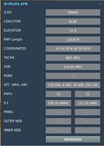
Thank you for your answer. Indeed the F10 map says that 109.1 is the ILS for runway 13 I didn't choose Al Dhafra, that's the airport for which the included Instant action mission was done for so it was the easiest to practice ILS landings. Guess I'll have to do my own mission. EDIT: Since I became aware that the ILS on the airfield could be the culprit I had a look at the Caucasus bug list and guess what, the Vaziani airfield (for which the campaign mission is done) regularly pops up has having a bad ILS too. So I basically tested the system on two airfields, find it not to work on two airfields, field in a bug report because I thought if it's not working on two airfields then there is a bug in the aircraft, to finally conclude that indeed I chose two buggy airfield to learn to use the ILS... Grrr

-
Yesterday I tried the 3rd mission of the M2000 campaign and didn't managed to get the ILS to work so today I tried another mission (Persian Gulf, night landing) and it didn't work either (for what it's worth the synthetic runway didn't work better): none of the ILS symbols (box, lines...) were displayed on the HUD nor on the HSI. They only appeared once I had landed (pretty useless at this point). A track is available attached to this post. I have the correct frequency for the ILS and it was set to On, the PCA shows APP selected and the waypoint 2 was chosen (Al Dhafra runway 13) with correct true heading and slope, as you can see in the track. If I am doing something wrong please tell me, otherwise can someone have a look at this ? Thank you in advance Track recorded on DCS 2.9.0.47168 Open Beta ILS_notworking.trk
-
I have the same issue.
-
@Flappie IRL the faster, the better for GBU (within launch parameters). The added speed gives the bomb energy to make more important course correction, especially at the end. Actually several -34 manual state an optimal GS of 500 kts at release for the optimal precision.
-
To my knowledge SAMP stopped manufacturing bombs (more precisely bombs' body, the filling was done by an other company) because there were not enough orders from the French government. So it was more logical from an economic perspective to source bombs from a foreign supplier. And the French government wasn't very logical either if I remember correctly : at one point the SAMP factory received help from the government to (re)establish a bomb production line but after the first batch of production there was no subsequent order (I think to recall that there was an order but with such volume and short planned delivery that only a US supplier could do it). Nowadays SAMP resumed the production of bombs (I think) but they no longer use their own design : they license build Mk-8X. I believe this has to do with ease of integration onto the plane : the ballistic was not the same between Mk-8X and their proprietary design so the plane manufacturer had to integrate both designs, one for the French with SAMP ballistic and one for foreign customer, usually with Mk-8X ballistic. For a more related to the topic consideration : I think to recall that old SAMP bombs usually had a different weight distribution than the Mk-8X bombs. The casing was lighter and there were more explosives inside, hence maybe the damage difference ingame (even if it might be exaggerated). I am looking for a source to back up my defective memory. None found in my archive however I have found several websites claiming 123 kg of explosives for the SAMP 250 (50% of the mass are explosives) instead of 89 kg for the Mk-82 (35%). I don't know how much blast 30 kg of explosives add but it would be difficult to balance due to the rudimentary damage model in DCS : on one hand more explosive means a stronger blast/a greater blast radius, on the other hand the lighter casing may imply smaller, lighter fragments that travel less and less initial penetration before the bomb body breaks so smaller cratering effects perhaps. Reason for edits : I add details as I found them online.
-
Having the TGP in either AREA TRACK (Litening) or SCENE (ATFLIR) mode should be enough : you shouldn't need to press the TDC to designate. However if you are in SCENE mode with the Litening then you definitely need to press the TDC in order to designate the reticule (if you prefer this name) as you target point. At least this is what I've experienced but I would like to be sure, hence why I opened this topic. This is the main difference between the two pods in my opinion : the SCENE mode with the Litening you have to depress the TDC to designate while it's not necessary with the ATFLIR in SCENE mode. Currently the SCENE mode and the AREA Track mode of the Litening both behaves similarly except for the inability to move the reticule in AREA TRACK. I'm not sure that's correct IRL : I assume the SCENE mode of the Litening is a ground stabilized INR mode however it seems a bit too insensible to drift (in DCS) if that's the case. Currently it's not working this way : I tried unchecking and checking the realistic TDC slew option but it didn't change its behaviour while using the TGP. It did change its behaviour when the TDC is allocated to the radar though. Maybe I'm wrong and I'm unwilling to test it now because it's a bit late but that's not always correct I think : if you undesignate once while in SCENE mode with the ATFLIR then the pod revert to INR and the cursor is no longer ground stabilised. The diamond is visible with the Litening pod if both the reticule and the target point are at the same spot in SCENE mode. With the ATFLIR it's visible in SCENE mode when the pod has not yet locked the picture and in Designation mode. Currently I have been unable to see the offset cursor : It might have been removed following the controversy about it's real world function VS the way it worked in DCS.
-
I'm fairly confident that's not how it work actually in DCS (Open Beta up to date 22/01/2022).
-
Actually this is a very good question. Because having the beam above the horizon is no guaranty there won't be any clutter IRL : their could be a mountain above the flying aircraft, returns from heavy cloud, ground returns from side lobes... And the radar has no mean to know if those conditions are met beforehand. If the ground clutter filter is removed while looking up, it means that in search modes it might be difficult to keep the false alarm rate under control and in track mode removing it might not be enough to keep the track. Keep in mind that the radar of the F-18 in A/A is only using range ambiguous waveform so even if there is a tremendous amount of distance separation in the physical world, in the ambiguous domain, clutter can still be in the same range cell as the useful signal. In DCS I'm under the impression that all radars deactivate the ground clutter filter when looking up since false alarm rate is not really represented anyway (except maybe in the M2000 after the recent upgrade) but is it really the case IRL ? (I don't really know though if that's public available knowledge, maybe it's part of ED generic radar behaviour because there is no better info available).
-
Hi everyone, I have been looking in the manual and in several Youtube tutorials however I have not found a detailed explanation on how the target point logic works in relation to the TGP. Here is what I understood : (assuming you have designated a waypoint and assigned HOTAS control to the TGP) LITENING II : LOS on the designated waypoint, TGP in SCENE mode. Moving the LOS with the TDC does not change the target point until you have done a TDC depress (reticule changes to a diamond). If you move again the TDC (the reticule revert to a cross) you'll again need to do a TDC depress to move the target point to the LOS. If you initiate tracking in either AREA TRACK or POINT mode, it will automatically move the target point to the LOS. TDC depress will allow you to move the Offset cursor. ATFLIR : LOS on the designated waypoint, TGP in DESIGNATION mode. You can't change the LOS with the TDC until you have done a TDC depress. Once it's done you can slew the LOS and the target point will follow no matter if the TGP is in INR, SCENE or AUTO mode. Is that correct ? If not, could you share how you understood it ? Thank you for your help.
-
I'm trying to figure out how the sight is supposed to work and I stumbled upon this thread. Even with the picture uploaded by finger I am not sure of what's going on : - I thought the Missile/Gyro switch only changed the axis of motion of the piper (Gyro = two axis, Missile = only vertical axis). However when I look at finger's picture I understand that vertical depression is never computed (not even to account for ballistic drop ?) in air to air when the switch is in the missile position, except in manual & gun mode. Is this the correct way to read the picture ? - When distance is written as D=400-600, does it mean the pilot can choose the distance manually with the twisting grip ? - The target span can be entered by using the red window in all mode except in the fixed 300 m mode, then it is red on the B&W scale, correct ? Thank you in advance for your answers.