AH_Sid
-
Posts
144 -
Joined
-
Last visited
Content Type
Profiles
Forums
Events
Everything posted by AH_Sid
-
I found a reference as to what this is for ........................................... eventually! :smilewink:
-
In our simulated F86F-35, there's a placard on the canopy switch I can't find anything in the real F86F manual to say the canopy was locked above this air speed or the switch inhibited (maybe I'm missing the reference, anyone seen this mentioned?). Currently in game, if you move the switch to open at a higher speed, the canopy is locked. As you decelerate, the canopy will open at 215 knots. The only reference I can find is in the 'airspeed and acceleration limitations section' Which doesn't say it physically can't be opened, just it may cause structural damage if you do open it above 215 knots, also no mention of the canopy detaching from the aircraft above this speed either. But in game the canopy will detach from the aircraft if you leave it open, or try to open it, above 165 knots When the above statement in the limitations section implies it's safe to open below 215 knots.
-
I've been running a few test comparing the before takeoff 'Emergency Fuel System Check' against what we have simulated for our F86F-35, there's few differences here. For reference here's the relevant pages from the F-86F Flight Manual. click for larger versions Emergency Fuel System Check I ran a series of test at Batumi (Altitude 37 Feet, Standard Pressure), using V1.5.2.48162.126 of DCS. With each test I changed outside temperature, starting at -50°c and worked up to +50°c in 5°c intervals, noting the max RPM achieved with both Normal and Emergency fuel selected. Then I plotted the results (red line) on to the graph from the manual. The rpm does drop with temperature, but as you can see it's way off, less than 100% RPM only being achieved once below -36°c. The manual states that the emergency fuel system is set to give 99% rpm on a 100°F (+38°c) day. and with a temperature hotter than +38°c, to be careful not to over speed the engine as higher than 100% rpm could be achieved. The manual also states I take this to mean the sudden fuel surge when the emergency system kicked in would send the exhaust temperature soaring way above limits if the engine wasn't already at a high enough rpm (or at a low enough idle rpm so the EGT would remain within limits). If you switch the Emergency Fuel on at say 70% or 75% nothing particularly abnormal happens at the moment, the EGT hardly changes. This is mentioned again in the Emergency Procedures section, if it was considered safer to ditch straight ahead, rather than try switching the Emergency Fuel switch on below 80%, the consequences of doing so must have been fairly catastrophic! Lastly, when switching back to the Normal fuel system (switching the Emergency Fuel switch Off), there should be a bigger drop in RMP initially, because the main fuel regulator took time to recover from the disabled condition. At the moment switching from Normal to Emergency and Emergency to Normal both cause same small rpm drop. Summary of differences and problems. 1) The maximum engine rpm with the Emergency Fuel system engaged needs adjusting to match the temperature graph. 2) Switching the Emergency Fuel switch On below 80% rpm (not including idle) should cause dangerous engine overheating or compressor stall. 3) Switching from Emergency Fuel to Normal Fuel should cause a bigger rpm drop than going from Normal to Emergency.
-

Link to SLI requests on Nvidia Forums and Crossfire on AMD Forums
AH_Sid replied to Lt_Maverick's topic in 2D Video Bugs
Request added on both GeForce threads. -
Yes
-
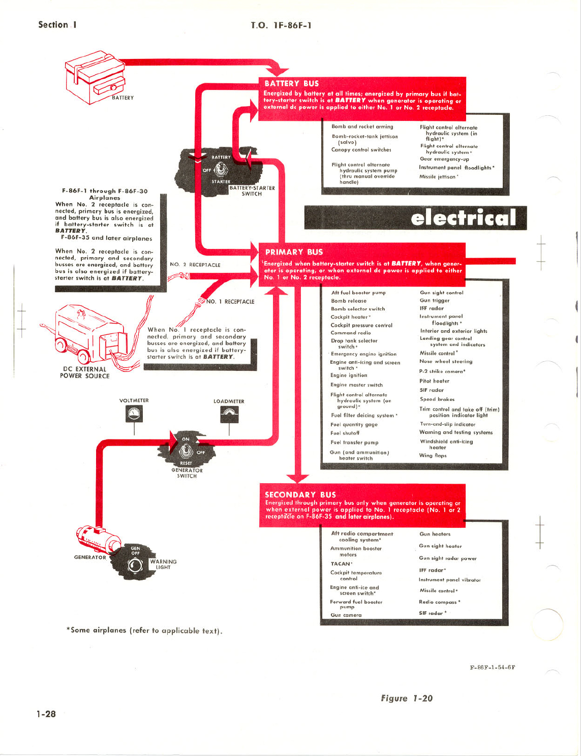
I've just been looking at this a bit more, it would appear the load meter is taken from the generator, so in my tests above where ground power is connected, it quite rightly shows a load of zero. The same with the airborne test with the generator turned off (switch on the right forward console) and the Emergency Override pulled (pump constantly running, connected directly to the battery), again the it quite rightly shows a load of zero. The load meter is only going to show the load the generator is supplying. So the load caused by the Alternate Hydraulic Pump is only going to show when Ground Power is disconnect, and the Generator is Online (Generator Light Out). Of course the load will vary as the Alternate Hydraulic Pump switches on and off as it cycles.
-
Many thanks cofcorpse Great to know the Alternate system pump output is correct as it now, thanks for confirming this (although it still surprises me there is such a big difference).
-
Thanks cofcorpse, yes that makes sense now. As mentioned here the aircraft is at IDLE (around 30% RPM), but as stated later in the manual, idle rpm varies with altitude and temperature. This increase in idle speed seems to be correctly modelled, for example: Senaki-Kolkhi, Altitude 39 feet, Temp +18°c gives at idle of 30% Beslan, Altitude 1772 feet, Temp +15°c gives at idle of 33% McCarran Intl, Altitude 2051 feet, Temp +21°c gives at idle of 35% Groom Lake, Altitude 4459 feet, Temp +30°c gives at idle of 40% So in 2.0 the idle is likely to always be high enough to have the light out (generator on) because of the altitude, unless you set the temperature extremely low.
-
Re-reading that, it does say "rated generator output is not available until engine rpm is approximately 45%" So is the generator warning light going out at 35% because the generator is producing some output, just not rated output?
-
It's stated in a couple of locations in the manual that the generator output is not available until engine rpm is approximately 45%. In the current public build ( V1.5.2.48162.126), the generator is coming online incorrectly at 35%.
-
Here's what the manual says about it. There's not too many adjustments you can make to it, other than rotating the dial so the heading at the top matches the aircraft heading (or if you want to fly in a particular direction, rotate the dial so that direction is at the top, then turn the aircraft until the needle points straight up), and the Fast Slaving switch (only the one on the instrument panel is clickable, and it's debatable whether it should have this switch in both positions, or just one or the other). It should be more accurate than the standby compass (the standby suffering a lot of error from all the metal work and wiring around the cockpit). As long as both are generally the same (+ - 10 to 15 degrees), go with what the Directional Indicator (DI) is saying. If they are vastly different, Fly straight and level, and push the Fast Slaving switch to realign the DI. There's a little bit more about how a Flux Gate Compass works, about half way down this web page
-
I think that's already been fixed Razor, The nose wheel steering is hydraulically power by the Utility Hydraulic system (which is always available with the engine running regardless of rpm), with electrical power for the nose wheel steering button coming from the primary bus (which is powered by the battery if the generator is off line). The only items you should lose when the generator is offline (engine below 45%), are the items connected to the secondary electrical bus. The current steering problem is just down to wind influencing the rudder more than pilot, just set the wind to zero in any mission you want to fly for now.

-
Yes it's a bug that crept in with the latest version, it's been reported. The wind is overpowering the rudder inputs in the latest 1.5.2 build
-
[use .8 runtime] problem with 0.7 Oculus DK2 with DCS 1.5 installation
AH_Sid replied to popov's topic in Multi-Display Bugs
Likewise, 1.5.2 works fine for me runtime 0.8 and Nvidia driver 359.06 -
I've been running a few test comparing the before taxi 'Flight Controls Hydraulic System Check' against what we have simulated for our F86F-35. Generally it's modelled well, but I've noted a few differences and problems. For reference here's the relevant pages from the F-86F Flight Manual. click for larger versions The below tests were carried out at Senaki-Kolkhi using the default 'Cold Start' mission (Altitude 39 Feet, Temp +18°c), using V1.5.2.48162.126 of DCS. The very first note tell us to perform these checks with the throttle at IDLE. It doesn't mention any altitude or temperature restrictions, so I assume these checks could be made at all airfields under all conditions, but this becomes relevant performing the first check. Normal System Check 1. Works Ok, with the warning light Out and pressure steady at around 3000 psi. 2. Works Ok, with the pressure returning at a reasonable rate. 3. Works Ok here, but with some effort. The change-over happens correctly at around 700 psi, but the controls need quite a lot of movement to bleed the pressure down to that amount. As mentioned above the aircraft is at IDLE (around 30% RPM), but as stated later in the manual, idle rpm varies with altitude and temperature. This increase in idle speed seems to be correctly modelled, for example: Senaki-Kolkhi, Altitude 39 feet, Temp +18°c gives at idle of 30% Beslan, Altitude 1772 feet, Temp +15°c gives at idle of 33% McCarran Intl, Altitude 2051 feet, Temp +21°c gives at idle of 35% Groom Lake, Altitude 4459 feet, Temp +30°c gives at idle of 40% But as the idle speed increases, so does the output of the engine driven 'normal' hydraulic pump, meaning with the idle speed much above 30%, the normal system simply can't be 'bleed-down' sufficiently to perform the change-over. I think the amount the normal systems drops when the stick is being moved rapidly like this needs increasing so the check can be completed at all airfield altitudes and conditions. Alternate System Check 1. Works Ok, with the warning light On and pressure around 2750 psi, but the pressure is meant to be 'Cycling' between 2550 - 3200 psi here, not maintaining a constant pressure. There's no description of how fast the cycling would have been, but bear in mind this was a before taxi check not a maintenance check, so I wouldn't have expected the system to take 5 mins to drop from 3200 to 2550 and then build back up again. Personally I would have thought something in the order of a 3-4 seconds for the pump to push the pressure up from 2550 to 3200, then maybe 10-15 seconds for 'designed leakage' to drop the pressure back to 2550, ready for the pump to kick back in and pump it up to 3200 psi again, so a cycle every 15-20 seconds would seem reasonable if you're asking the pilot to check it at this stage before taxi. 2. Works Ok, proper control movement. 3. Works Ok, the 'bleed-down' is much easier on the alternate system and correctly changes-over at around 750 psi. But note how long the system takes to rebuild the pressure back up! The NORMAL system takes around 12 seconds to rebuild the pressure, the ALTERNATE system takes 67 seconds. That strikes me as a huge difference for two systems that where both tasked with doing the same job. I haven't seen technical specs for pumps, but I'm surprised there's this huge difference even given the fact the Normal system pump was engine driven and the Alternate pump electrically driven. 4. Works Ok, the light comes On. 5. Works Ok, the light goes Out, and the NORMAL pressure is around 3000 psi. Emergency Override System Check 1. Works Ok, Flight control switch can be held at RESET. 2. Works Ok, Emergency override can be handle pulled Out, pressure rises correctly to 4000 psi (Non-Cycling). 3. Works Ok, Alternate warning light is Out. 4. Works Ok, proper control movement, pressure drops. But again note how slow the pressure is to rebuild (250 - 4000 psi takes 82 seconds) 5. Works Ok, Flight control switch released to NORMAL, Alternate warning light comes On. Pressure remains at 4000 psi (Non-Cycling). 6. Emergency override handle In, pressure incorrectly remains at 4000 psi. Due to the 'designed leakage' the pressure should drop back to 2550 and begin 'Cycling' between 2550 - 3200 psi again. 7. Works Ok, system resets to normal, light Out, and NORMAL pressure Ok. Load Meter All the above tests were carried out with the engine running, battery switch on, ground power on, and the generator selected on (but with the idle speed below 45% it shouldn't have had an output anyway). At no stage did the Load Meter appear to show any load. I'm not sure of the circuitry with the ground power on (does the Load Meter show a load at this stage?). But even in flight, if the generator is turned off (switch on the right forward console) and the Emergency Override pulled (pump constantly running, connected directly to the battery), the Load Meter doesn't show this heavy load. Summary of differences and problems. 1. The NORMAL hydraulic system needs to 'bleed-down' at a higher rate, so the change-over can be checked even at higher altitude airfields on a hot day (but not so high the system changes over during 'normal' flight though). 2. The ALTERNATE hydraulic system needs to cycle between 2550 - 3200 psi when not under load. 3. Possibly increase the ability of the Alternate system pump to rebuild the pressure to something more similar to the Normal system pump. 4. After the Emergency Override Handle has been pushed back in, the system should return to cycling between 2550 - 3200 psi when not under load. 5. Should the Load Meter show a heavy load whenever the Alternate system pump is running.
-
Many thanks for this, I look forward to trying it out.
-
The Virtual Horsemen fly the F-86 at Nellis AFB
AH_Sid replied to VH-Rock's topic in DCS: F-86F Sabre
Very nice! Beautiful flying and filming. -
Thanks
-
This was noted as fixed, but it's still not functioning correctly in the latest public build (V1.5.2.48162.126). The 'Longitudinal Alternate Trim' switch should hold in the 'NORMAL GRIP CONT' and 'OFF' positions, but should be spring loaded back to 'OFF' whenever the 'NOSE UP' or NOSE DOWN' key bindings are released. The Same applies to the 'Lateral Alternate Trim' switch, it should hold the 'NORMAL' and 'OFF' positions, but be spring loaded back to 'OFF' whenever the 'LEFT' or 'RIGHT' key binding are released. If you compare them to the Rudder Trim Switch (which is spring loaded correctly), you'll note as soon as the button or keystroke assigned to 'Rudder Trim Switch - LEFT' or 'Rudder Trim Switch - RIGHT' is released, the switch returns to the 'OFF' position. But with the 'Longitudinal Alternate Trim' and 'Lateral Alternate Trim' switches, the switch position is maintained after button/keyboard release.
-
I find it strange that this button would have been duplicated like this, there's no reason to have it fitted both on the instrument panel and the right forward console. Perhaps the statement "... on the instrument panel or on the right forward console." doesn't suggest it was fitted in both locations, but rather one or the other. In which case it might be better to remove one or the other and not have both.
-
Yes agreed, we have the text for the test switch 'LDG. GR WARN. LT. TEST', but the push button itself has been replaced with a panel fastener. Of course this test button illuminated the light in the landing gear handle, the 'Landing Gear Unsafe Warning Light', which itself is not modelled yet (as noted here). If our F-86F-35 doesn't have this test button, then the text shouldn't be there either and pushing the 'Landing gear warning horn cutout button' should test the light instead.
-
DCS Has stopped working message whenever I try and load a mission
AH_Sid replied to AH_Sid's topic in Game Crash
Yes 359.06 -
DCS Has stopped working message whenever I try and load a mission
AH_Sid replied to AH_Sid's topic in Game Crash
Yes, I tried : . Running the 'Repair DCS World OpenBeta' from the windows start menu. . Manually deleting the 'DCS.openbeta' folder from my 'Saved Games' folder. I tried both several times, still crashed every time I started a mission. In the end I : .Uninstalled 'DCS World OpenBeta' using the uninstall page in Window Control Panel. .Deleted both the 'DCS.openbeta' folder from my 'Saved Games' folder, and the 'DCS World OpenBeta' folder from the main Eagle Dynamics folder. .Re-download the 1.5.0 install files and installed them. .Re-upgraded 1.5.2.48162.126. .Re-installed my aircraft This time I've only loaded the F86F and Mig15 (I had all the aircraft and campaigns installed before). -
DCS Has stopped working message whenever I try and load a mission
AH_Sid replied to AH_Sid's topic in Game Crash
Still no idea what the problem was, but I've got it running again after a complete re-install of the Open Beta. -
I installed version 1.5.2.48162.126 today, now I get a windows "DCS has stopped working" message whenever I try and run any mission. Previous 1.5.1 version ran ok, and the DCS World 2 OpenAlpha V2.0.0.47610 is still running ok on this machine. I've tried run to repair, and I've tried deleting the 'DCS.openbeta' folder from Saved Games. Any other suggestions? Logs.zip