LJQCN101
-
Posts
509 -
Joined
-
Last visited
-
Days Won
1
Content Type
Profiles
Forums
Events
Everything posted by LJQCN101
-
 Fixed internally.
 -
The same goes for T.O.1F-16CM circa 2007 and F-18 EM chart, do you able to find those online? HAF manual is not the correct one for the version DCS models, but yeah some aspects like fuel flow chart from it is comparable.
-
This is the figure for sea level and M0.55.
-
This assumption is wrong. Most figures from the JF-17 T.O. Dash-1 and RD-93 tech manual like thrust curve/fuel flow curve vs altitude & mach, detailed fuel flow of different cruise settings with different stores etc. are still NOT PUBLIC. We don't just put those docs on the internet by the request of random people.
-
The thrust of 22k lbsf or 10,000kgf actually happens at sea level and M0.85. While at 30,000ft and M1.6, the thrust is only around 7,100 kgf, with a Fuel Flow of 16,500 kg/h. So yeah, the in-game FF should tweak up a bit. But weirdly, when I compared the installed RD-93 fuel flow curve (FF vs alt & mach) to the one in GAF T.O.1MIG-29-1, which is the real life MIG-29G manual (you can find that if you could), I even found the RD-93 a bit more fuel efficient. For comparison, the Mig-29G does 30,000ft & M1.6 at 10.25 kg/sec, which is 36900 kg/h for both engines, so 18,450 kg/h for single engine.
-
Thanks for your feedback and this will soon be revisited. In addition to your info, the TSFC of 2.05 actually happens at H=0 & M=0 with uninstalled engine, in training-combat mode of RD-93. Expect a surge to 2.40 when at H=0 & M=1.0. With combat mode, this would be 2.08 (H=0 & M=0).
-
G limit also automatically changes to 6G above M0.85 under A2A mode.
-
The issue might be the pitch integrator as some users have pointed out, for example: In a diving turn, you actually provide an easier task for the pitch integrator to eliminate the difference between commanded g and actual g, with the help of gravity. Decrease/increase in speed or thrust settings also has an impact. Maybe this explains why you're able to reach 9g faster when diving.
-
Just a side note, Ps = (v/g)*(dv/dt) + dh/dt. So if you keep a constant altitude (dh/dt = 0), the SEP can be derived from aircraft velocity (v) and the change of velocity between timeframes (dv/dt). This is often the way to calculate SEP from flight test raw data. Also,
-
fixed [REPORTED]Low altitude, Low fuel, High speed wobbling
LJQCN101 replied to Quetzalkoatl's topic in Bugs and Problems
Yeah timestep/dt can be a cause too. I remembered the adaptive dt back then. -
fixed [REPORTED]Low altitude, Low fuel, High speed wobbling
LJQCN101 replied to Quetzalkoatl's topic in Bugs and Problems
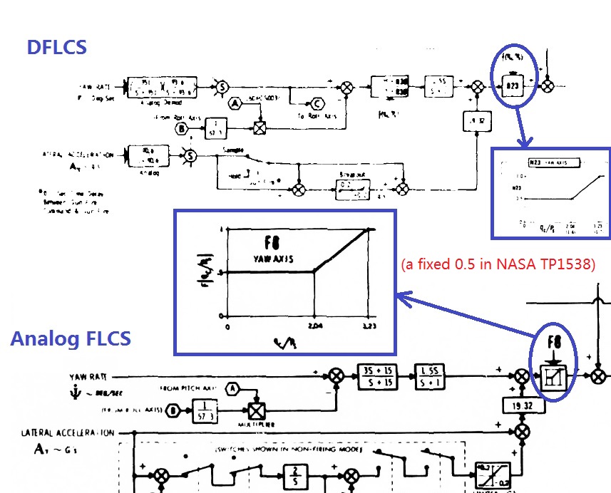
You can experience a high frequency long period yaw oscillation well below 800kts just by kicking the rudder. Neither the frequency nor the period can match a normal dutch roll mode. I'm not sure this is a wanted behaviour and may result in a bad control quality rating according to MIL-STD-1797A, which provides guidance in evaluating aircraft controllability and handling. Some users in the forum and reddit, like Curly and mav-jp, suggest that the FLCS used by DCS F-16C may be based on NASA TP1538: (https://forums.eagle.ru/showpost.php?p=4096586&postcount=82) This is not unreasonable since yaw oscillation can happen if the Yaw Axis Gain is too high for the current speed/altitude. And in NASA TP1538, the Yaw Axis Gain is a fixed 0.5 and is unsuitable for high speed flying since it seems that the gains are simplified for subsonic flight. In Analog and Digital FLCS, the Yaw Axis Gain is scheduled with Qc/Ps which takes speed/altitude into account. Maybe the pitch axis has the same problem of gain scheduling, but I could also be wrong and the problem may come from elsewhere. :joystick:
-
The BRM-1 is a pretty draggy loadout and due to it's design and the lack of a nose cone/dome, it's Drag Index is comparable with a GB-6.
-
[Upcoming EFM update] Further refinement of lift & drag coefficients
LJQCN101 replied to LJQCN101's topic in JF-17 Thunder
No preliminary changes has been made into current patches. The FM update also addresses some of the anomalies I knew so yeah you can do some testing again when it come out. -
Hi guys, Hope you enjoy the flight model of JF-17 so far. We'll be updating the CL & CD tables of JF-17 aerodynamics data in the next OB update, to bring the overall turn performance closer to the EM chart. As a result, the SEP characteristics of the aircraft will be more accurate among all flight regimes. Which means you'll notice small changes in acceleration, deceleration and speed bleeding in a turn. Stay tuned.
-
Try not exceeding 195kts and not braking at high wheel speeds. BTW the term 'TEF' and 'LEF' are also seen in F-16 and F-18 manuals (T.O. Dash-1 and NFMs). While I have not seen the term 'slat' being used in those manuals. Technically speaking slats are different from LEFs.
-
Wheel Brake problems. Brakes are always locked
LJQCN101 replied to DmitriKozlowsky's topic in Bugs and Problems
The only parking brake is at the Brake Panel, which I think you didn't turn on since it's placed to NORM position. Could you take screenshots of the axis tuning and axis mapping page of the pedals? I'll see if I can find something. -
The JF-17 do have a fade-in module to switch gains smoothly but there was an implementation bug in it before. Now it's fixed and I think you can try that again. I happen to know the F-16 control law and it has a similar function too.
-
Yeah, it also looks like a pitch-up maneuver coupled with rolling is quickly creating sideslips, but a certain gain schedule (maybe somewhere near the lateral acceleration feedback) in the yaw FLCS is too high for this airspeed/altitude and wants to quickly eliminate that sideslip, causing the rudder to oscillate. Just my two cents.
-
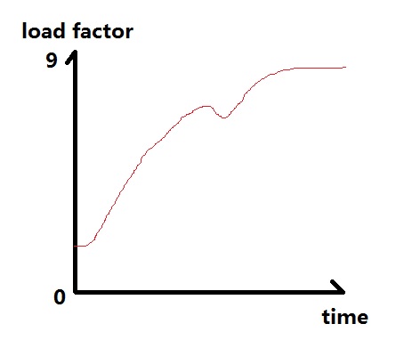
I think OP means there's a rocking in pitch-up maneuvers, with inconsistent G evolution rate. Nothing to do with the roll here. A testing of short period pitch mode should reveal this. For example simply draw a graph of pitch rate vs time, or load factor vs time, using step input to see how the aircraft responses. By watching the video it looks like this:
-
[NO BUG]negative g, red vision , manual pitch ovveride
LJQCN101 replied to luigipsic's topic in Bugs and Problems
Looks like it should be -3gs. The negative 'g' limiter is scheduled as a function of dynamic pressure. Here's the one directly from the control block diagram and I've checked that it's the same for both Analog and Digital FLCS (FSD phase), which are the only publicly available ones. A dynamic pressure of 34 psf roughly equals to 100 knots, and 184 psf roughly equals to 250 knots. So you're able to command -3g above approximately 250 knots, which agrees with the 2008 manual mvsgas has described, and also the HAF ones. With MPO engaged, this limit will be overridden and fixed to -4 in the system (means -3g). That's why there's a MPO check during the starting process to see if it's working properly.
-
fixed Maximum commanded pitch rate in take-off & landing gains
LJQCN101 replied to LJQCN101's topic in DCS: F-16C Viper
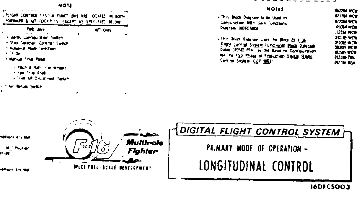
It's a DTIC document, you can search for it from the official site. And it states that it's for the FSD phase of production DFLCS. What I posted is an official graph with revision number on it, those who recognise it will know. And I don't think you can find detailed info about maximum pitch-rate command of take-off & landing gains in Flight Manuals, at least I tried with the HAF ones, unless someone has the actual control block diagram with the right revision number. -
fixed Maximum commanded pitch rate in take-off & landing gains
LJQCN101 replied to LJQCN101's topic in DCS: F-16C Viper
If they've got the exact control block diagram for the block 50 DFLCS circa 2007, there shouldn't be any "tweaking" of any kind. All transfer functions, gain schedules etc should be kept as is and the whole graph is coded line by line. -
fixed Maximum commanded pitch rate in take-off & landing gains
LJQCN101 replied to LJQCN101's topic in DCS: F-16C Viper
My bad it's a F-16D, but it is block25 DFLCS according to the graph, for the FSD phase of production DFLCS.
-
fixed Maximum commanded pitch rate in take-off & landing gains
LJQCN101 replied to LJQCN101's topic in DCS: F-16C Viper
It is pitch rate command system as you can tell from the control block diagram that in take-off & landing gains, the filtered Nz signal get multiplied by 0.0. AOA feedback above 10 degrees is also in the diagram so I don't see a problem here. What I'm talking about is exactly how the system handles pitch rate feedback. True but that's a simplification of what a control block diagram can tell. But you can always try to match the numbers to see if it was changed in block 50 DFLCS circa 2007. As I've implemented like 3 different versions of F16 FLCS years ago, including NASA, Analog and Digital ones, I can pretty much spot the differences if you provide more info from the relevant manual. -
fixed Maximum commanded pitch rate in take-off & landing gains
LJQCN101 replied to LJQCN101's topic in DCS: F-16C Viper
It's the F16B block25 DFLCS control block diagram from DTIC ADA 189675. The whole diagram may not be relevant to the current modelled block 50 but I think the pitch rate feedback part is correct. *EDIT: F16D actually.