LJQCN101
-
Posts
509 -
Joined
-
Last visited
-
Days Won
1
Content Type
Profiles
Forums
Events
Everything posted by LJQCN101
-
Could be a bug of automatic take-off trim. There's some take-off/landing roll characteristics improvements on the way, for example: https://forums.eagle.ru/topic/264361-too-much-nose-down-pitch-moment-on-landing/ Not sure if it's gonna make it into the next update according to ED's update timeline.
-
A bug due to inconsistency with EFM and lua in 2.7 update. Related: Both are fixed internally.
-
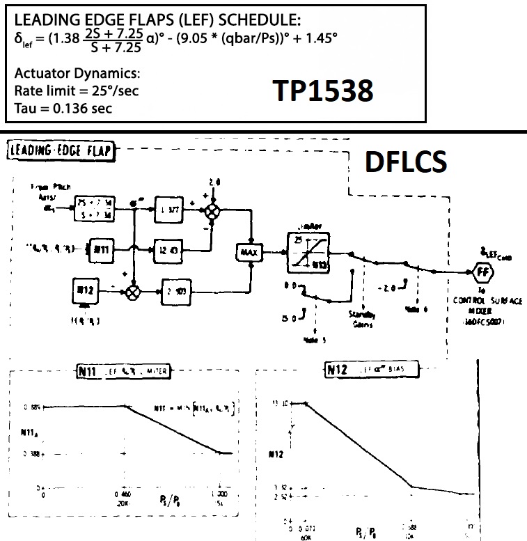
 Yes, lef as I mentioned, and sb is speed brake. One could just use the control law to calculate how much deflection the LEF would be, but note that DFLCS uses a different schema than the one in TP1538.
-
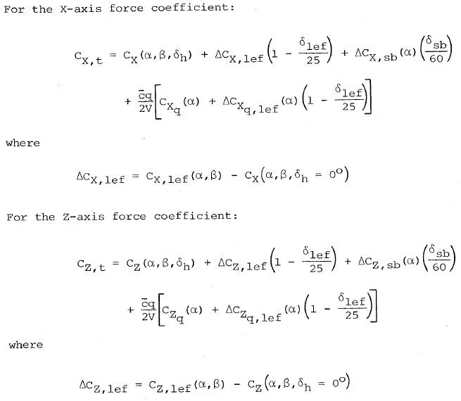
NASA TP1538 has steady flow Cx and Cz tables for Mach 0.6, 30,000ft. But it also uses pitch rate derivatives Cx-q and Cz-q to calculate total Cx and Cz, and also delta LEF tables. So you would also need to account for LEF and pitch rate in such cases, and then transform them back to CL, CD. (From body-axis to wind-axis.) Elevator position would be close to zero in a lower mach steady turn due to relaxed static stability so I think one can just use 𝛿h=0 in those tables. We also need to find out pitch rate and that one could be tricky, rendering the result not so reliable I guess. Just pointing out a direction.
-
Su-30MKK Full fid or FC3 version?
LJQCN101 replied to TaxDollarsAtWork's topic in Deka Ironwork Simulations
Just some preliminary EFM and multi-crew preparation, didn't take much time.- 320 replies
-
- 13
-

-

-
Su-30MKK Full fid or FC3 version?
LJQCN101 replied to TaxDollarsAtWork's topic in Deka Ironwork Simulations
I did take a look though, which adds to the already abundant info regarding flight control systems and autopilot (SDU, SAU). Anyways I've already completed coding the exact longitudinal FBW according to the diagram, looking good. (That's a lot simpler control logic compared to the JF-17.)- 320 replies
-
- 14
-
-
-
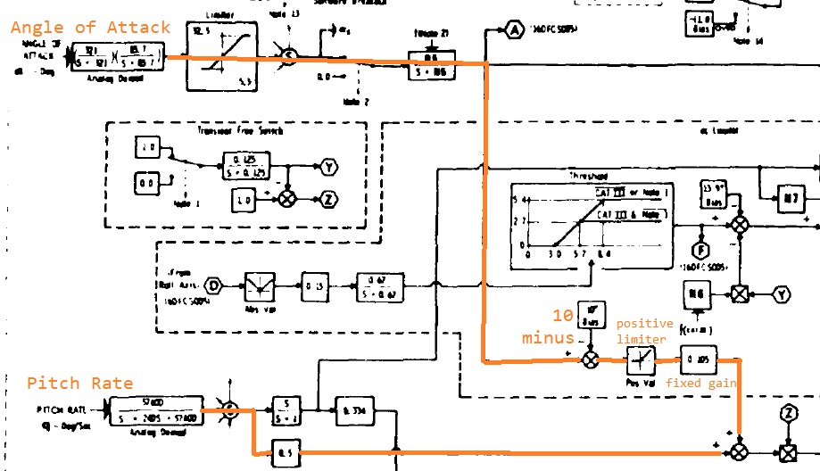
While the Hornet tends to hold a trimmed AOA with flaps down, the Viper on the other hand is designed to hold a zero pitch-rate in hands-off flight when FLCS is in Take-off & Landing Gains. The Take-off & Landing Gains is a pitch-rate command system until 10 deg AOA, which means your stick is commanding pitch-rate, instead of G or AOA. A zero stick input will translate to a zero pitch-rate, regardless whether your aircraft is inverted, decelerating or accelerating. When flying above 10 deg AOA, the Viper's FLCS starts to add nose-down command to your stick input, a negative pitch-rate command proportional to (AOA - 10). It's called a blended pitch-rate and AOA command system. All of these behaviors are very different than in the Hornet. There's one thing worth mentioning however. Let's say you manually trimmed to 13 deg AOA level and steady flight in the Viper. The pitch trim is added to the stick input, so you're essentially commanding a positive pitch-rate, while the FLCS is commanding negative pitch-rate proportional to (AOA - 10), since you're currently above 10 deg AOA. What's happening is that the aircraft will now tend to hold the trimmed AOA, and it flies like a Hornet with flaps down. Adjusting the throttle will now pitch the nose up and down.
-
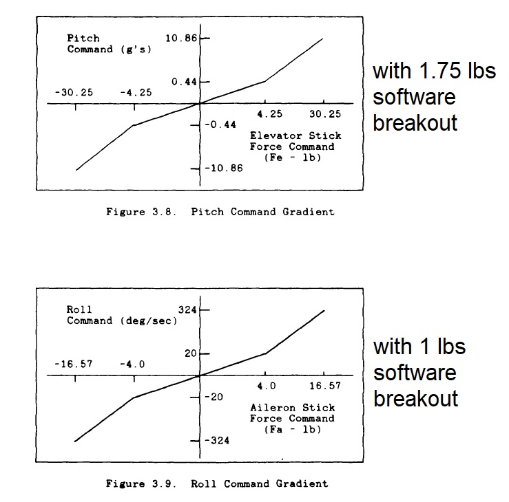
It could be that your input is within the DFLCS software breakout (deadzone), which is -/+ 1.75 lbs for pitch and -/+ 1 lbs for roll, so that DFLCS disregards your input.
-
DCS models a full range of 32lbs stick force range, instead of the stick force required to pull 9G (which is 25lbs), so G command will saturate at 78.125% simulated stick force range. Also the F-16 DFLCS has built-in stick gradients (curves), including deadzones. That may explain the non-linearity of pitch response.
-
Hi, yes there's currently too much of nose-down pitching moment on touch-down and landing-roll compared to real life. Working on it.
- 1 reply
-
- 4
-
-
I haven't been able to reproduce and nothing changed regarding FCS. Are you flying through wake turbulence of other aircraft? (Or if the cockpit is too hot or too cold, the virtual stick would jerk by itself indicating the pilot is uncomfortable.)
-
Could you upload a short video illustrating the issue, with control indicator (ctrl+enter) turned on? I'd like to know the flight conditions you were in.
-
The pitch axis is statically unstable in certain AOA regions and subsonic regions. Your stick commands G or load factor in up and away flight, so what you'll see is that the elevator initially deflects to increase load factor. When approaching the commanded load factor, the elevator just returns to neutral to hold the load factor. This behavior is shown in the FBW demonstration video: After landing, the elevators were wobbling around because the AOA and pitch-rate feedback is still active. It wobbles as in real life, but not as crazily as in DCS F-16.
-
This is pretty normal behavior. The roll axis uses a mixture of CAS and mechanical control. The CAS translates stick input to roll rate command. Roll rate feedback is included to make sure a fixed stick position equals to a certain roll rate. (But it's not perfect since it's just proportional control). This will result in a relatively linear roll rate response as you deflect the stick. There're three stages that the CAS is working to provide such an roll rate response: 1. When you initially deflect the stick, the current roll rate of the aircraft is much lower than the CAS commanded value, so CAS deflects the aileron (up to 5 degrees max limit). At the same time the mechanical control deflects the aileron too, so what you'll see initially is that the aileron deflects a lot more than you stick asks. 2. Considering roll inertia, roll rate sensor delay, and the limited authority of CAS, the roll rate response of the aircraft tends to overshoot when roll rate is rapidly reaching the CAS commanded value. When this happens, the CAS tends to deflect the aileron in the opposite direction to stop the roll rate from further increasing, hence what you saw. (The ailerons returning to neutral.) 3. Since the roll axis is statically stable, you'll need positive aileron deflection to hold the roll rate. When the current roll rate of the aircraft reached CAS commanded value, the CAS commands aileron to move back to hold the roll rate.
-
The engine requires sufficient inlet pressure to be able to reliably ignite afterburner.
-
In OFP Tape M1, having to depress and hold the uncage button is a requirement to help prevent an inadvertent AMRAAM launch. (Same in the HAF CJ manual.) Not sure if later tapes changed such a function, or the USAF one is different. (We're currently modeling M4.2/4.3?)
-
The red squares indicate your controller positions, and the green ones indicate flight control system outputs. So it shows that you have some right rudder input.
-
FSSB force and curves settings?
LJQCN101 replied to VIXEN413's topic in Controller Questions and Bugs
AFAIK DCS do model the DFLCS built-in command gradient, that is 32lbs for pitch and 17.57lbs for roll, including software breakout (deadzone). So it's better to use no curve for FSSB settings. Note that you only need 25lbs to command 9G, while DCS models a full range of 32lbs, which means the g command will saturate at 78.125% simulated stick force range. The F-16 DFLCS command gradients:
-
The only realistic way of recreating the flight control system is to use the actual control block diagram, otherwise the devs are just 'making up' the control logic hence 'fake' the handling characteristics. No statements being made doesn't mean they didn't do so. I'm familiar with the F-16 DFLCS control logic as well and I can tell DCS F-16CM has handling characteristics matching what is depicted in the corresponding block diagram.
-
The JF-17 FCS control law is implemented line by line according to real life control block diagram, and there's no dedicated refuelling mode unfortunately (not like F-16 who switches to landing gains for refuelling). But you can place the config switch into AG2 which will reduce g/pitch-rate onset. Increase the tanker speed above or equal to 315 kts also helps since the g-command system doesn't handle so well at lower speeds.
-
F-16C LDG Maneuverability Authority & Extend/Retracting Transition
LJQCN101 replied to dtpilot247's topic in DCS: F-16C Viper
Related reports: https://forums.eagle.ru/topic/253139-reportedinstant-transition-between-cruise-gains-and-take-offamplanding-gains/ https://forums.eagle.ru/topic/214915-maximum-commanded-pitch-rate-in-take-off-amp-landing-gains/ -
Ah you’re right, the RD-93 engine oil pump is driven by the KCA-54 accessory gearbox. So there should be no PM until engine rotating.
-
Yes, there's a booster pump located at the bottom of tank 2, which is driven by a DC electric motor, and is used to provide fuel during engine starting and also normal operations.
-
PM: oil pressure (kgf/cm2) PT: fuel filter differential pressure (kgf/cm2) PT1: afterburner injector fuel pressure (kgf/cm2) VE: engine vibration (mm/s)
-
There's no authentic modelling of FBW in any falcon4 versions until mav-jp coded it line by line using the actual FLCS diagrams in BMS. He has already answered this question to you at here.