LJQCN101
-
Posts
509 -
Joined
-
Last visited
-
Days Won
1
Content Type
Profiles
Forums
Events
Everything posted by LJQCN101
-
It should, as -1 put it the Take-off & Landing Gains is a pitch-rate command system until 10 deg AOA (meaning AOA < 10). Neutral stick means zero pitch-rate when AOA < 10. When MLG WOW, there's some modification to the control law: 1. AOA input/feedback sets to 0. Meaning you won't get that pitch down command when AOA > 10. 2. Pitch integrator stops integrating and gradually returns to 0, turning the pitch axis from a PI controller to a P controller. Meaning any uncommanded pitch-rate would be cancelled out to a lesser extent. Steady state error between command and feedback could persist. 3. Pitch command doubles. 4. Other minor changes such as additional structural filters.
-
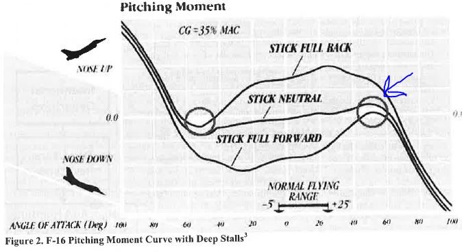
The above mentioned 35 alpha I knew of, is seems to be the AOA at CLmax (also known as the stall AOA), according to the 0.6 mach wind tunnel test of a sub-scale model of an early F-16, in NASA TP-1538. This is a test of the base model, which means control surfaces are at 0 deflection in this case (including LEF, which is normally auto scheduled with AOA). The deep stall AOA however is around 55-60 degrees, according to the Cm curve from the same wind tunnel test.

-
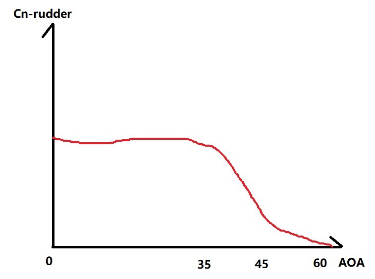
As for the yawing moment coefficient (Cn) created by the rudder, it remains pretty much constant from 0 to 35 degrees AOA, and then plummets into approximately 0 at 60 deg AOA. No magic included. As mentioned above, the directional stability (Cn-beta) become negative (unstable) at above 27 degrees, which also means you'll get less yaw dampening moment to counter the yawing moment created by the rudder, hence more sensitive rudder.
-
The relaxed static stability (RSS) characteristics of the JF-17 enables the aircraft to create positive pitching moment up til around 60 degrees AOA with full elevator deflection leading edge down. Surely you can still pitch-up the aircraft at 70 knots, if the AOA is less than 60 degrees. (Just watch how the elevator stays at neutral position when holding the turn at 27 degrees AOA, and think about how the aircraft would behave when the elevator fully deflects.) The F-16 is known to be able to do the same. I'll post the Cm curve of F-16 for example, as a typical characteristics of an RSS aircraft. The main reason for the AOA limiter to exist is that: 1. Nose-down pitching moment plummets as AOA increase above 30 degrees. 2. Directional stability becomes negative (unstable) at above 27 degrees. Try staying at an AOA region between 30-45 degrees (using EFCS) and notice the wing rock aggravating. Any side-slip created would further decrease the ability for the elevator to generate nose-down pitching moment. 3. Rolling while pulling (and even worse if kicking the rudder into the roll) at the same time risks overshooting the AOA limit due to a phenomenon called inertia roll-coupling, to where the nose-down pitching moment created by the elevator is not enough to suppress the rapid pitch-up. Kicking the rudder at around AOA limit would especially be very dangerous, which is why the F-16 imposes an rudder authority reduction law to prevent the pilot from making rudder input at high AOA, but JF-17 doesn't have such features. As a basic rule, you're not allowed to pitch and roll the aircraft at the same time for more than 360 degrees bank changes consecutively, or making bank to bank pull & roll for more than 180 deg bank changes. Your video just demonstrates the typical relaxed static stability characteristics, which other RSS aircrafts such as F-16/Su-27 also possesses, but with less inertia. For more info try the three EFM & FCS demonstration videos at:
-
The A version of J-11 family has the same engine as Su-27S. The note of thrust_sum_max and thrust_sum_ab has no meaningful implications.
-

JF-17 AI unit almost twice as much thrust BUG
LJQCN101 replied to GumidekCZ's topic in Aircraft AI Bugs (Non-Combined Arms)
The real thrust values that are used for SFM calculation are in the table_data under 'engine' section. You can safely ignore thrust_sum_max and thrust_sum_ab. -
In -1 section 6 Flight Characteristics, Landing Configuration, there're two described techniques that you can use to land a Viper. One is the 11 deg technique: stick for attitude and throttle for AOA. The reasoning behind is that the FLCS Take-off & Landing Gains is a pitch-rate command system until 10 deg AOA, which means your stick is commanding pitch-rate, instead of G or AOA. A zero stick input will translate to a zero pitch-rate, regardless whether your aircraft is inverted, decelerating or accelerating. This technique allows better pitch control. Another technique is to trim for 13 deg AOA: stick for AOA and throttle for glidepath. When flying above 10 deg AOA, the FLCS starts to add nose-down command to your stick input, a negative pitch-rate command proportional to (AOA - 10). It's called a blended pitch-rate and AOA command system. When you manually trimmed to 13 deg AOA, you're essentially commanding a positive pitch-rate, while at the same time the FLCS is commanding negative pitch-rate proportional to (AOA - 10). What's happening is that the aircraft will now tend to hold the trimmed AOA. Adjusting the throttle will now pitch the nose up and down. This type of approach primarily allows better control of touchdown point and more efficient energy dissipation, but less stable in gusty wind conditions.
-
Landing with stores, fuel tanks, and CAT III configuration
LJQCN101 replied to Al-Azraq's topic in DCS: F-16C Viper
Cross checked with -1, it also states that in takeoff and landing gains, the STORES CONFIG switch has no effect on limiting or gains. -
Landing with stores, fuel tanks, and CAT III configuration
LJQCN101 replied to Al-Azraq's topic in DCS: F-16C Viper
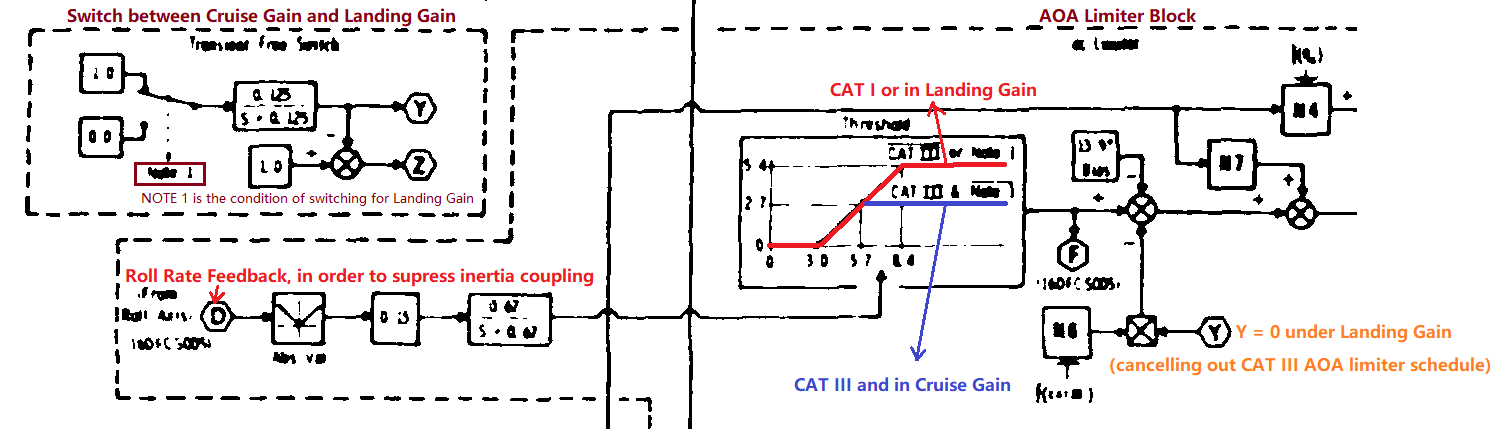
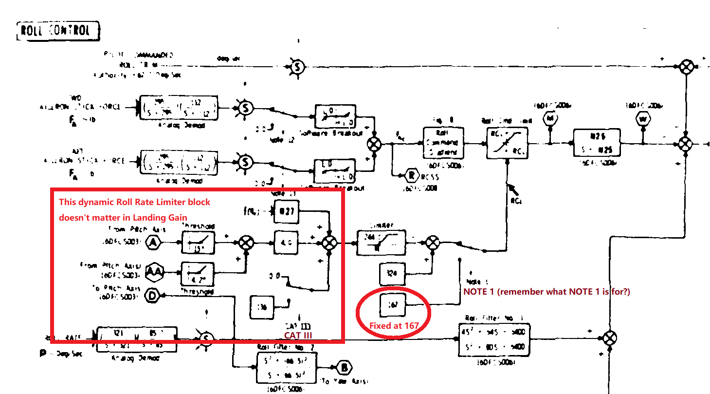
Myth buster time. Actually the CAT I/III switch doesn't matter in Take-off & Landing Gains. (Calling landing gains for less typing below.) For the Longitudinal DFLCS, the CAT III AOA limiter schedule is multiplied by zero (nulled) under Landing Gains. And there's yet to see any extra filtering of command signals or feedback signals due to CAT III. For the Lateral DFLCS, the roll rate limiter output is fixed at 167 deg/s under Landing Gains, overriding any dynamic roll rate limiting schedule of CAT I/III and Cruise Gains.
-
IIRC if you select 'SY' (avionics system) as Wind Source in SMS CNTL page, the system will use either the 'system measured method' or the 'system computed method' to estimate wind data. The other two options are MP (DTC loaded value) or PI (pilot entered value). To use the system measured wind data method, the pilot must fly the aircraft within 20nm of the target and also 0 - 3000ft above the target in order for the system to obtain a valid measurement. The system computed winds method may be used as an alternative. It measures the current wind at aircraft altitude and linearly extrapolates its speed down to the burst altitude. The Wind Quality assessment of this method is LOW, which means the handed-off wind speed will have less effect in the computations.
-
[FIXED] Drag chute does not get replaced after rearming
LJQCN101 replied to Rabbisaur's topic in Fixed Bugs
The chute is replaced exactly at the moment when the ground crew announces "refuel complete" or "rearm complete". Did you wait for the ground crew to inform you that they have completed the action? -
IIRC the wind settings are used to calculate the WCMD dispense point, so that if the wind data are accurate, the dispensed munitions will drift over the target. If the Wind Source setting is set to Pilot Entered (PI), then the manually entered TGT WD settings (bearing/speed) are used. If set to Mission Planning (MP), the DTC values are used. If set to Avionic System (SY), the avionics system measured or computed wind data will be used. Just a simplified description (not copied from manual). For more info on wind quality, how the system extrapolates the wind speed etc., please refer to OFP tape M3.
-
[CHK] Instability on rotation for Takeoff and Landing
LJQCN101 replied to Hawkeye91's topic in Bugs and Problems
Hi, the auto rotation function is not an emergency function, but rather to assist manual rotation by deflecting the elevator for an extra 8 degrees when main wheels are WOW and airspeed greater than 108 kts. It's unlikely that the auto rotation function engages at landing, since it only re-energizes when airspeed drops below a certain threshold, but I'm still looking into the issue where static instability occurs. There'll be some small adjustments in take-off/landing roll behavior in the next update. -
The flaperons have a maximum command deflection of 20 degrees down and 23 degrees up. At landing configurations, the opposite one is already at 20 degrees down position acting as TEF, so there's no room for it to further deflect down.
-
It's a requirement that all normal landings should be made with speed brakes opened to the 43° due to a floating tendency associated with ground effect. Some minor notes: Minimise roll input at touchdown as it retracts an aileron and causes decreased lift. The ARI (aileron-rudder-interconnect) is also cut-off at touchdown, meaning any roll input before touchdown will cause a rudder deflection, and that deflection will immediately decreased to 0 at touchdown, causing a transient yaw rate.
-
Su-30MKK Full fid or FC3 version?
LJQCN101 replied to TaxDollarsAtWork's topic in Deka Ironwork Simulations
I haven't checked. Is there any player tested data like level acceleration SEP in m/s? RL flight manuals have Vy charts for those figures. -
It do seems like they are calculated charts and not flight tested. I have a flight tested chart of the same conditions as above, and it should look like this for 8km and 11km:
-
Su-30MKK Full fid or FC3 version?
LJQCN101 replied to TaxDollarsAtWork's topic in Deka Ironwork Simulations
The J-11 uses ED's PFM so we don't have a say. If possible I would also like to change the way SDU and SAU systems are implemented as they apparently are not 100% based on real-life block diagrams. -
can not reproduce Severe Flight Modeling Glitch. Post Stall behaviour.
LJQCN101 replied to twistking's topic in Bugs and Problems
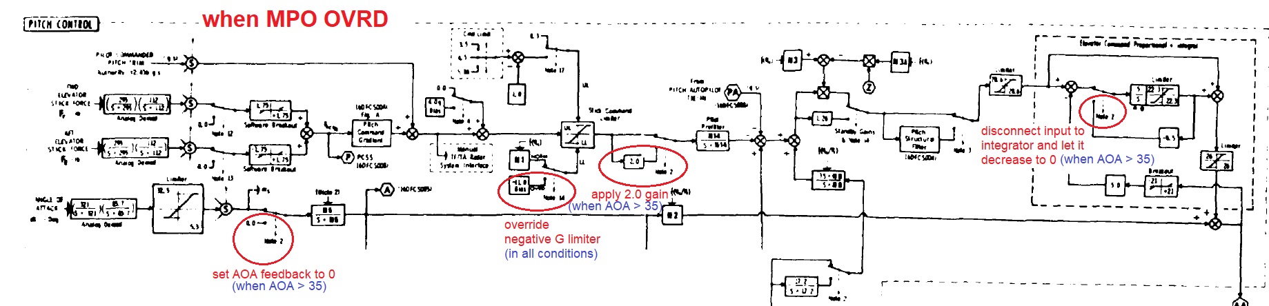
You basically won't be able to use the MPO in a dogfight unless you use it in the negative G direction. It can only override AOA limiter (actually sets AOA feedback to 0) when AOA > 35 degrees. Here's what MPO OVRD did to the longitudinal FLCS: EDIT: The current MPO implementation seems to be correct, except that the maximum allowed negative G should be -3G, instead of the current -2G.
-
JF-17 cannot autopilot under unbalanced mounting.
LJQCN101 replied to travelaround's topic in JF-17 Thunder
Hi, sounds like it's a bug that was introduced in 2.7.0 and should be fixed in 2.7.1. What's your DCS version?- 1 reply
-
- 1
-

-
You can perform a cobra or tail-slide or with a VTOL and pause at 90 deg AOA to see whether the acceleration values are based on wind axis or body axis. Watch out for gravity components though. Stay away from 90 deg pitch. In EFM we calculate the acceleration components in body axis at sensor position by ourselves, which will also include the pitch/yaw rate effect on accelerometers, compared to those at center of gravity.
-
Hi, a review of DEEC control logic is underway. Although the block diagram we got for DEEC is not as detailed and low-level as the one for FCS, but we'll try.
-
I didn't spot any anomalies in CL CD curves or the testing results of SEP, and the FBW is line by line coded according to the real graph. Are you accelerating above M0.85, since that would have your g-limit reduced to 6g. You would be mostly flying at a lower AOA than an F-16 due to it's lower wing loading, thus a lower induces drag. (Unless you load it up.) Other than that the CL and CD themselves at subsonic regions are roughly on-par with an F-16, with less wing reference area. Being limited to 6g means you'll be pulling very little AOA, hence the impression of not bleeding energy. Anyways we need the following info to check if SEP at any specific point is correct or not: airspeed bleed rate, mach number, G, AOA, altitude, fuel and loadout, power settings, ambient temperature.
-
Just a matter of sample rate and resolution for HUD. In ADC (Air Data Computer), the static pressure has a resolution of 0.0005hg and the dynamic pressure of 0.001hg, with a gradient tolerance of -/+ 0.3%. For comparison, the Flight Control Computer samples and monitors them every 60ms. (Even less for AOA, angular rate and acceleration sensors.)
-
Hi, we're sorry to inform you that there's currently a bug in AP that will prevent it from holding the bank angle. Unfortunately the fix didn't make it into this patch.