LJQCN101
-
Posts
509 -
Joined
-
Last visited
-
Days Won
1
Content Type
Profiles
Forums
Events
Everything posted by LJQCN101
-

Why it's hard limited to 6G when speed higher than Mach 0.85?
LJQCN101 replied to Kumabit's topic in JF-17 Thunder
The shift in center of focus usually results in drastic change in pitching moment if you're changing speed rapidly. The problem usually reveals when decelerating rapidly through transonic regions where static stability rapidly decreases and for the same elevator deflection, you're able to create more pitch-up moment, causing a tendency to overshoot the aircraft structural limit. The closest aircraft I found with a similar G limit is the Mig-29, which allows 9G below m0.85 and 7G above m0.85 (if gross weight is below 14200kg), and 8G below m0.85 and 6G above m0.85 (if gross weight is above 14200kg). Although you can overcome the G limit by applying extra force on the stick (same as Su-27), but the pilot irl is not allowed to override the stick kicker. Speaking of Su-27, it has a similar arrangement but there're 3 different FBW G limit values for subsonic, transonic and supersonic, and varies with gross weight. The pilot irl are also prohibited from overriding the limit. The JF-17 took a conservative approach which does not vary its FCS G limit based on gross weight. -
Sorry but your beloved DCS F16 Manual also states that: Indeed it's modelled in DCS, but a simple testing of pitch response reveals that it is just take-off and landing gains, working as intended.
-
Well I do and so does the F16 FLCS SME at https://forums.eagle.ru/forum/englis...80#post7136080. But clearly you don't. I don't think there's any reason for anyone to continue the talk with someone who won't prove anything and qualified in nothing, while judging others and saying they are wrong. Nobody cares here. Good luck living in your own world. And you don't know jack about F16 FLCS, period.
-
There's no manual that gives a better picture than a control block diagram. The FLCS engineers use the diagram to actually IMPLEMENT the software logic. So there's no better sources, thanks. Again, you proves nothing.
-
It is mentioned in both T.O.1F-16CM-1 and the DFLCS control block diagram that it uses take-off & landing gains, the latter of which is used by FLCS engineers and maintainers and may not be known to pilots. I sincerely do not trust any other sources other than engineering sources so could you state your sources or qualifications. I'm very curious to know how it's different from take-off & landing gains in terms of command types, command gradient, feedback types, feedback gains, etc.
-
Proves nothing unless you studies the actual DFLCS diagram. It is the same logic as the take-off & landing gains. Source: F-16 Digital Flight Control System Functional Block Diagrams. Data obtained from Lt. Bruce Peet, F-16 System Program Office, Wright-Patterson OH. Also in -1:
-
As someone who knows the actual DFLCS control block diagram, there's no such things as "refueling mode". It just reuses the control law as in take-off/landing gains. There's a switch to determine whether to change the logic:
-
No changes in the flight model in last OB update except for elevator actuator rate and engine inlet total recovery coefficient. The way Tacview calculating AOA and TRT is dubious since I can even see it flying at 29 AOA at 380kts, which is impossible. TRT can be mis-calculated if there's a rapid change in AOA. Try flying a sustained level turn at 340-360 to see if it can reach 24deg/s. (It's also in the normal range of max-instantaneous turn rate so it really depends on situations.)
-
Hi, the control law has a built-in breakout (deadzone) and lag filters to your stick input, to prevent saturating the elevator and destabilising the system, so yeah it does create lags. There's no special refuelling law for the JF-17 and the g-command system doesn't handle so well at lower speeds, so you may want to try refuelling at higher speeds (i.e. 315 kts). Also putting FCS config to AG2 lowers g-onset rate so it might help.
-
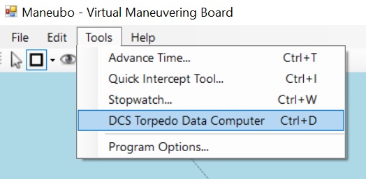
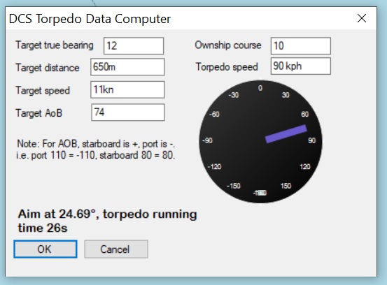
Since 093 is updated with manual targeting capabilities, allowing you to fire the torpedo to where the periscope is aiming at, I thought it maybe useful to provide some kind of calculation tool. The program is built upon an excellent open source project Maneubo, which maybe useful in the future due to its TMA (Target Motion Analysis) function. v0.8+TDC.zip Angle on Bow (AOB) guide: https://www.subsim.com/tips/wolfpack/aob.htm Source code: https://github.com/LJQCN101/Maneubo

- 1 reply
-
- 4
-

-

-
Su-30MKK Full fid or FC3 version?
LJQCN101 replied to TaxDollarsAtWork's topic in Deka Ironwork Simulations
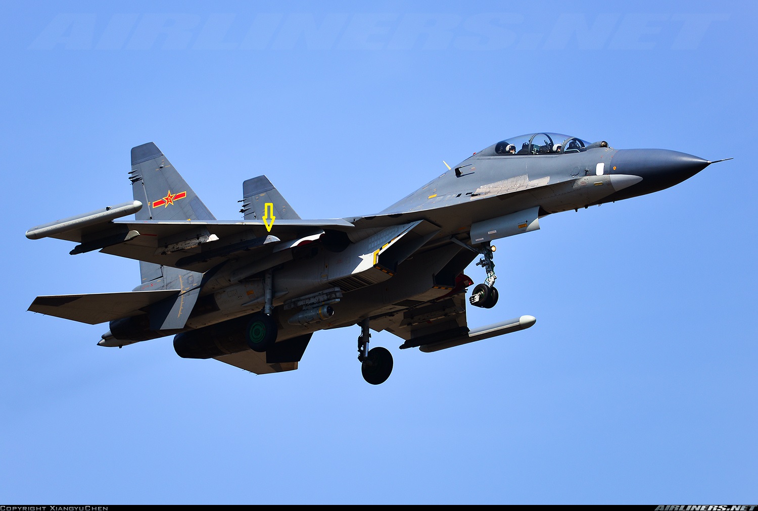
Well, there're 12 pylons on MKK too. There's not too much picture showing the 4/9 pylon.
-
fixed [REPORTED]AoA decreasing with increasing speed/g-load in to/lnd gain
LJQCN101 replied to bbrz's topic in Bugs and Problems
Seeing that a few FLCS issues are being looked at ATM, may i bring up this one. -
Su-30MKK Full fid or FC3 version?
LJQCN101 replied to TaxDollarsAtWork's topic in Deka Ironwork Simulations
Not decided yet, depends on attainable data. So don't put your hopes up too high. -
The exact value can be found in the DFLCS block diagram. https://forums.eagle.ru/showpost.php?p=4058809&postcount=3 The graph is too blurry and I cannot really tell if it's 130 or 134. But this value is exactly 40% of 324 deg/s, which is the maximum commandable roll rate in DFLCS.
-
Ps = (v/g)*(dv/dt) + dh/dt. In RL Flight Manuals it is very specific that you find your sustained turn rate at Ps=0 curve, which means your airspeed AND altitude may not change when performing such a turn. You may find turn rate chart with Ps curve in T.O.1F-16CM-1-1, and explanations of sustained turn rate in AFTTP (Air Force Tactics, Techniques and Procedures) 3-3 Vol.5
-
Seems like due to the transonic aerodynamic center shift, pitching moment changes rapidly in this region. I guess you can overshoot 9.0G when rapidly decelerating through transonic speeds.
-
That sounds weird. The 8.5G hard limit (0.5G steady-state error) seems like the proportional-integrator failed to eliminate the error between the commanded value and feedback value. But it's hard to tell where the problem is. Are you decelerating rapidly?
-
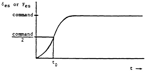
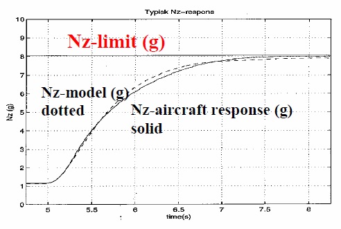
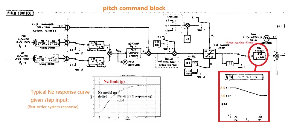
MIL-STD-1797A (DEPARTMENT OF DEFENSE INTERFACE STANDARD, FLYING QUALITIES OF PILOTED AIRCRAFT) could have some guidance. For pitch response verification, usually a step input is used, which means pulling the stick as abruptly as possible. But pulling a 25 lbsf force sensing stick under Gs is not the same as pulling a near-zero stick force joystick under 1G condition. The former would actually take more time to reach the maximum stick deflection/force since you have to confront such a large stick force, so it's not a true step input under test flight conditions. Pulling a zero stick force joystick abruptly would be closer to a true step input. Besides, the F-16 FLCS (including Analog and Digital) has a first-order filter at the end of the pitch command block to limit input rate and make the system a first-order system. A typical response curve of a first-order system is shown as below: In DFLCS, the filter rate is variable dependent on dynamic pressure. Basically if airspeed over 400kts, the k of the first-order filter (k/s+k) would reduce from 8.3 to 6.0, which means a slower filter rate. This is also to be keep in mind when testing the pitch response at different speeds.
-
I saw his blue line being topped at 9.3, that's why I guess something is changed. But we won't know util the patch drops.
-
https://forums.eagle.ru/showpost.php?p=4433620&postcount=34 Looks like dev build addressed this issue according to NL. Ideally the DFLCS diagram can be coded line by line instead of just using NASA/Analog FLCS as a baseline and changing values based on other sources.
-
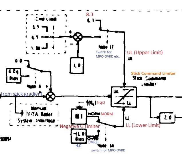
First I'll state the source I'm using. I'm not using anything from the flight manual because it is NOT a proper engineering source for coding the inner loop logic of FLCS. According to the DFLCS block diagram, the upper limit of the stick command limiter block is 8.3 (+1.0) = 9.3G. While I also have a copy of the block diagram of Analog FLCS, and the figure is 8.0 (+1.0) = 9.0G. So could the DCS F-16 be actually using the logic from Analog FLCS instead of DFLCS?
-
I'm talking about real life right now. For JF-17 it's able to sustain 8G at Sea Level 0.66 Mach with 2 x PL-5 and 50% fuel at Max AB, Standard Day. Above that speed your Specific Excess Power is greater than 0 even at 8G so your plane would accelerate. Those are in the EM Charts from flight manual. For F-16 it would be more prominent. It can sustain 9G (SEP = 0) at Sea Level 0.81 Mach with Drag Index = 50 equivalent of stores and gross weight of 26,000 lbs. For the trend of the SEP=0 curve it can even sustain 10G if there were no G-limit. Those are also in the EM Charts from flight manual. Well, just saying you can report this to the F-16 bug forum too.
-
This includes the changes of ISA (Integrated Servo Actuator) rate limit which addresses the issue of deflection rates being too quick. Not really an impact on control qualities. Fuel flow changes covers FF at military power at higher speeds. Previously there's a mistake that FF at MIL doesn't change with speeds. Cm0 means zero lift pitching moment coefficient. This patch basically adds more variation in pitch up/down tendencies among all speed/altitude and especially in transonic regions. Not really noticeable in a level flight since the FBW is constantly trimming for 1G (thanks to the proportional-integrator). But with rapid deceleration through transonic regions at higher Gs, there should be a tendency of pitching up and overshoot some Gs. But again, it would be soon compensated by the proportional-integrator. (Not so noticeable compared to a Su-27S who don't have an integrator)
-
That's weird, gonna check this.
-
https://www.doc88.com/p-3857487861687.html An interesting paper, titled "Su-30 test flight evaluation" by a test pilot from China Flight Test Research Institute (中国飞行试验研究院), in 1997. He was sent to Russia to test flight the Su-30 before China can make a decision whether to buy the aircraft. The flight control computer could be the СДУ-10У. On page 3: Translation: When changing speed below Mach number 0.85, the aircraft has an auto-trim function. The pilot barely needs to re-trim the aircraft.