Curly
-
Posts
169 -
Joined
-
Last visited
Content Type
Profiles
Forums
Events
Everything posted by Curly
-
The analog format of the indicator is actually how the IFLOLS works. The beam of light of light emitted from the display is very narrow close in. It diffuses wider the further away from it you are. At around 500 feet the light appears to fill a single lens. Once you get 20 feet from light source, the line is about an inch high. What’s really wild is that there is no centered lens. There are 12 lenses, hence no middle lense. The datum light are between the 6 and 7 lens. So when you’re looking at on glide slope, you’re seeing light from both the 6 and the 7 lens at the same time. https://www.airspacemag.com/how-things-work/the-meatball-8421491/
-
reported AN/APG-63 range is under-represented
Curly replied to GGTharos's topic in Flaming Cliffs Bugs & Problems
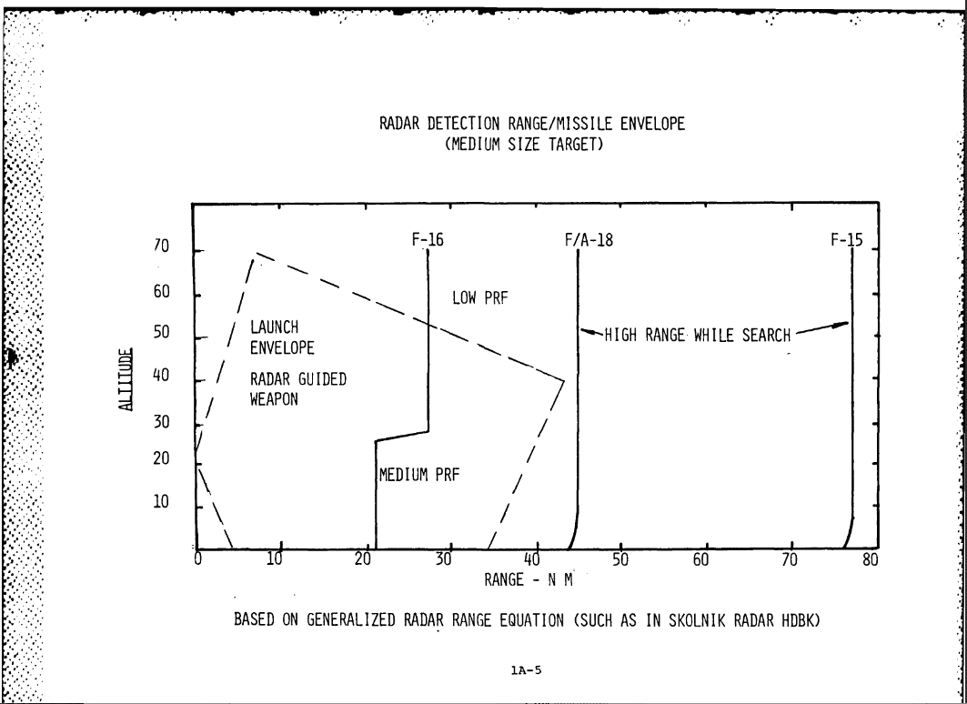
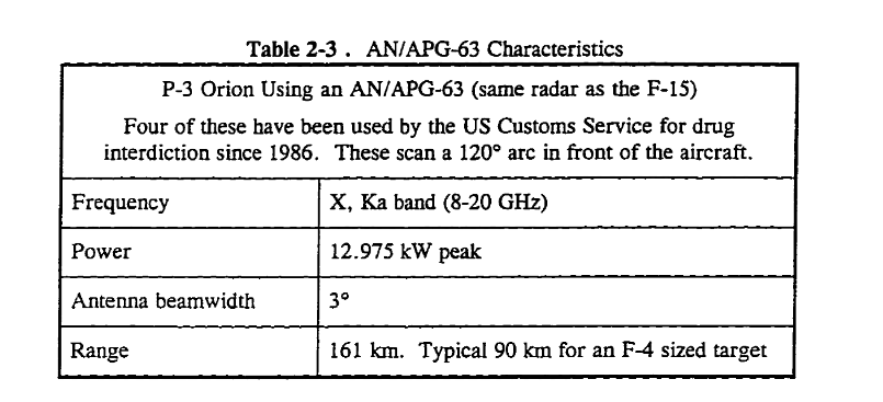
There is a pretty good case in the public literature for larger detection ranges from the apg-63. In game, I can resolve MiG 29’s (5m^2 RCS targets) in RWS high perf, at about 60 nautical miles (111 Km). 86-70 Nm in RWS seems theoretically possible given the publicly available data on the radar. This is a publicly available DOD report on the radar. Max Theoretical range in High Pref RWS is 78 Nm (144 Km). The US tends to use 5M^2 for fighter sized targets in it’s reports. https://apps.dtic.mil/dtic/tr/fulltext/u2/a142071.pdf The APG-63 dish size is 36 inches in diameter and has peak power is 12K watts. If we do a cursory sanity check on the DOD chart. With reasonable gain and P min figures, to calculate the theoretical range, using the idealized range equation mentioned in the report. The theoretical ranges from the DOD report seem good. The peak power figures come from this Public Canadian radar assessment. https://www.collectionscanada.gc.ca/obj/s4/f2/dsk2/ftp04/mq22118.pdf The I’ve seen Su-27’s n001 quoted as having a peak power of 4k. The capabilities are often quoted as detecting 3m^2 targets at 80-100 Kilometers. In game, high pref RWS resolves 5m^2 (mig 29’s) contacts at 60 nautical miles (111 Km). Which seems reasonable if you’re determining in game radar range by using maximum theoretical range. But it doesn’t look like that approach is applied to the F-15, given it’s shorter detection range. In range while search (RWS) mode, the F-15 loses 25% of it’s theoretical detection range. While the N001 is operating at the maximum theoretical range.
-
reported AN/APG-63 range is under-represented
Curly replied to GGTharos's topic in Flaming Cliffs Bugs & Problems
Is the 80 nm detection range in VS mode? -
The ball gets more sensitive the closer you get to it as function of geometry. This is true in DCS and in real life. In DCS the phenomenon is more drastic because of how the meatball is implemented in game. Closer to the IFLOLS, smaller deviations from glideslope are read as larger errors. A two foot error from glideslope still reads on the ball at 3/4 of a mile. Because at that range a centered ball is 11 feet high. When you get to the ramp, the glideslope “window” is only 1.6 foot high. So if you’re two feet above glideslope at the ramp you’re seeing 1 ball high. If you’re two feet from glideslope during you’re whole approach, You really won’t notice it until your at the ramp. If your two feet above the glideslope you’ll see a center ball window until your 230 feet from the IFLOLS. At which point the ball will suddenly move high. Not because you drifted higher, but because the window got smaller. In DCS you can’t see the windows getting smaller because the steps are discrete You are either in one specifics lights field of view or your are not. In the real world you would see the ball rising as you got closer. In the real world, at 1/4 mile if you’re 2 feet above glideslope, you would see half ball high. Since DCS has discrete steps you won't see an indication of change till you're outside a window. Just remember the magnitude of the changes have to get smaller the closer you get to the IFLOLS. Notice the discrete steps in DCS IFLOLS. Only one ball lit at a time, no halves.
-
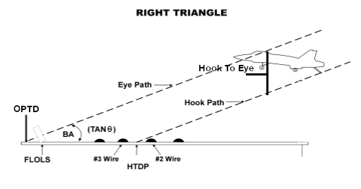
Hook to eye is a characteristic of the aircraft, independent of the vessel landing on it. Hook to eye is always 16.35 no matter what boat it's landing on. When hook to eye is changed, the roll angle of IFLOLS changes. This raises or lowera glideslope, though it stays at the same angle. The effect is to move the optical touchdown point forward or aft on the runway. That way no matter what size the aircraft the hook always lands in the same spot. About 20 feet aft of the target wire.
-
There are currently few things that are modeled incorrectly on the Stennis that lead to this issue. I'd really like to see more of them addressed too. First, the meatball guides the Hornet to land with the hook touching down right on top of the three 3 wire. The spot where the hook touches down is know as the hook touchdown point. It's wrong on the current Stennis. The hook touch down point should be about half way between the two and three wire, on 4 wire boats. This allows some margin of error on the approach and room for the hook to rebound on impact. Since the hook to eye distance is set for the Hornet; Any aircraft larger or smaller than the hornet will land with it's hook either aft or forward of the 3 wire. For every 1 foot difference in the hook to eye value, the hook touch down point moves forward and aft the runway 16.34 feet. The proof of which is some simple trigonometry; Tan of the glideslope (3.5) = 1/16.34. This is why you need to ride a hall ball down to catch a 3 wire in the Tomcat. The Hornet's hook to eye is 16.35 and the Tomcat's is 19.70. The 3.35 foot difference in hook to eye means, the Tomcat's hook will land 54.73 feet behind where the Hornet's does. Since the wires are supposed to be 40 feet apart you would be looking at a two wire for a perfectly flown ball on the current Stennis in the Tomcat. However results may vary because the wires on the current Stennis are not the correct distance from each other. There is also a bit of a problem with the current implementation of the IFLOLS on the Stennis which adds to this problem. The implementation of the IFLOLS is rudimentary. Each light has view angle of .13 degrees and if you're in that view angle, the whole light is lit. So at 1/2 mile you can move up and down 20 feet before the light jumps up to the next bulb. That's not how it works in real life. In reality, when your looking at centered ball you're looking at light from two sources at the same time. Since this isn't possible in DCS, you can never really fly a truly centered ball. Which wouldn't matter as much if, the hook touchdown point was where it's supposed to be. All of it could be fixed though. Moving the hooktouch down point is just a matter of moving the optical glideslope forward or aft. Making the IFLOLS work more correctly could be achieved by, allowing two light to be on at once and splitting each light into 3 segments. I too would like to see more of this talked about by ED now that pre sales have begun.
-
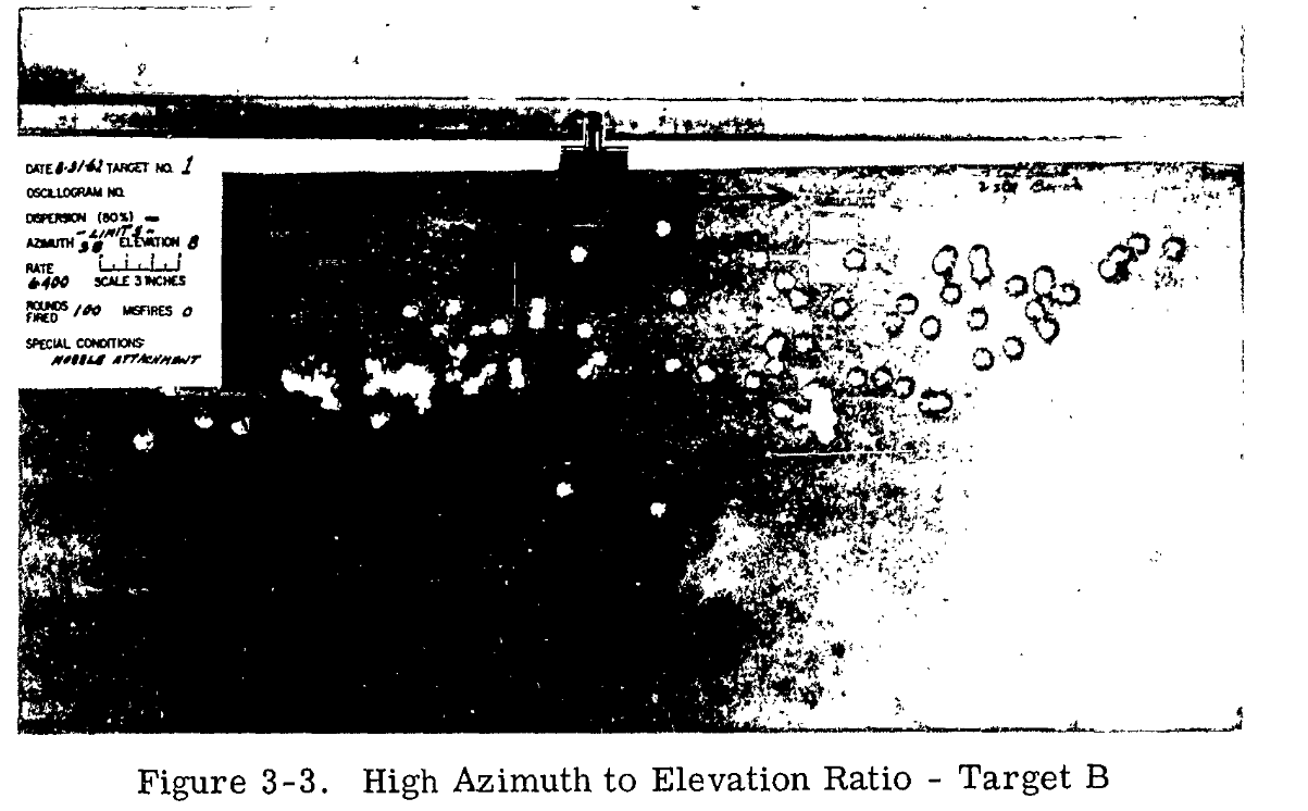
I don’t think anyone is disputing that a stock M61 Vulcan shoots 8 mil 80 %. However the gun can be rigged to shoot a wider dispersion pattern. This development report from 1962 discusses the type of rigging needed to change the pattern. https://apps.dtic.mil/dtic/tr/fulltext/u2/290637.pdf They modified the gun to fire 3 dispersion patterns which varied from the base pattern. First was a wider pattern with a high azimuth to elevation ratio ( and oval), The second was a larger circular dispersion pattern of 14 to 18 mils. The last pattern was a tighter dispersion pattern with a diameter of 4 to 6 mils. This tighter pattern could not be achieved during the tests. The oval pattern was achieved by modifying the barrel clamps. Which essentially changed the barrel length, in order to produce barrel whip. This resulted in an oval pattern of 50 mils in azimuth and 12 mils in elevation. Or 38 mils in azimuth and 8 mils in elevation, depending on the barrel clamp. The air defense version of the Vulcan operated by the Army, the M167, was issued with a similar barrel clamp for anti personal use. This barrel clamp is pictured in the manual for the m167 along side the stock circular barrel clamp. The 14 to 18 mil increased pattern was achieved by shimming the barrels at the barrel clamp. This increased the effective barrel length which resulted in a larger circular pattern of 16 mils 83%. This is what Yo-Yo was talking about in his previous post, the gun can be rigged to fire a variety of patterns and was done so operationally. He indicates that the gun on the Hornet is specifically rigged to shoot a wider dispersion than stock. If you wanted to find if that were true you would probably need to read the A1-F18AC-750-300 and A1-F18AC-750-100 manuals and see how the barrel clamps are rigged. He then goes on to state that the setting Da0 in the shell table is not the dispersion ratings in milliradians (mils). Putting .008 into the shell table won’t give a you a dispersion of 8 mils aka .008 radians. He states, a Da0 .0022 = 17.5 mils for the m61 and that 3 mils = .004 Da0 for the BMP gun. It’s implied in his statement, that the total dispersion is greater than median dispersion by a factor of 8, and the ratings given by militaries, in mils are the median dispersion. If I’m reading his comment correctly, the formula for dispersion in mils is: dispersion in mils = Da0 (from shell table.lua) * 8 This seems to hold true to the examples provided earlier (.0022 Da0) = 17.5 mils and .0004 = 3 mils 17.5 mils ~ .0176 radians = .0022 *8 And 3.2 mils = .0032 radians = .0004 * 8 It also explains why the Tomcats Da0 is .001 as it results in an 8 mil circle, which is apparently spec for the gun. 8 mils = .008 radians = .001 * 8 If you wanted to figure out another gun the formula would be mils/1000 / 8 = Da0 So if you wanted to mod the GAU-8 with an accuracy of 5 mils The setting in the shell table should be 5/1000/8 Da0= 0.000625
-
I posted the complete translation of the entire report a few pages ago. https://ww2aircraft.net/forum/attachments/diving_test_109f_w-nr-9228_ger_eng-pdf.81158/ What about it’s contents make you doubt that the aircraft was pulled out of the dive with the stick alone?
-
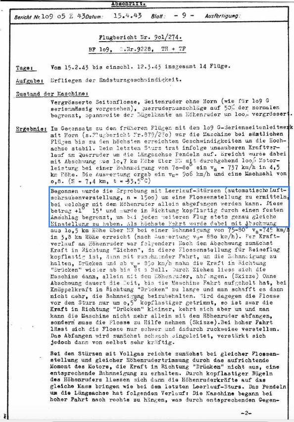
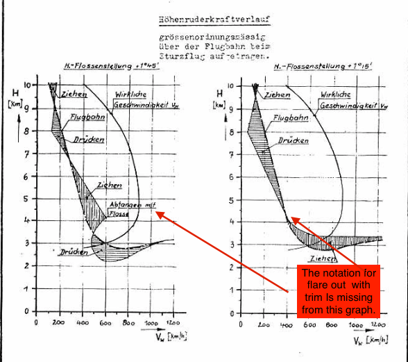
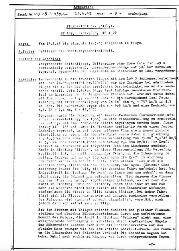
For 1 you don't consider, the that report says "This trials started with idle dives to estimate an horizontal stabilizer trim setting that makes it possible to recover a dive with the stick. This setting was +1 degree 15 minutes ." and that the report notes "the plane was pulled out of the dive with the stick alone." or that the second chart with the 1 degree 15 minute does not have note stating that the craft was pulled out of the dive with the trim. To be clear evidence that the craft was pulled out of a dive with a trim setting of 1 degree 15 minutes with the stick alone? here's the entire page from the report I'm referencing.
-
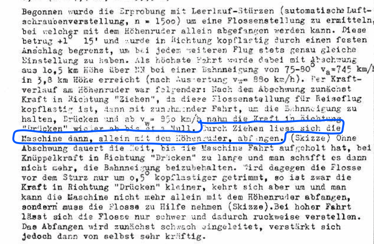
That's correct in first test they pulled out of the dive with the trim system. In the second test they did not use the trim system and pulled out of the dive with the stick alone. The purpose of the tests conducted on Feburaruy 15 to March 12 1943, is explicitly stated in the notes. "This trials started with idle dives to estimate an horizontal stabilizer trim setting that makes it possible to recover a dive with the stick. This setting was +1 degree 15 minutes and was blocked in the direction nose heavy by a stop to assure the same settings at every flight." "... After this the plane was pulled out of the dive just using the stick." As indicated by the chart on the right with the trim setting of +1 degree 15 minutes. The reason why they wanted to know the trim position was because they considered pulling out of a dive with the trim alone unreliable. "pulling out with the horizontal stabilizer trim is a potential danger (high g acceleration increase in the pull-out) so dive recover should be achieved without changing the position of the horizontal stabilizer." "If you trim the elevator just .5 degrees more nose heavy the force in the direction push is less but it is not possible to recover just by using the stick, it is necessary to use the horizontal stabilizer trim. At high speed the horizontal stabilizer trim is heavy and just jerkily moveable." The reason these test were conducted was to "investigate insufficient elevator controls at high mach numbers". They were trying to make the craft safer by making it possible to recover from a dive with the stick alone. They also ran into problems with this trim setting when testing powered on dives. The pilot could not maintain the necessary amount of push force needed to keep the aircraft in a dive with the power on. “In a full throttle dive despite previous trim to +1.7° just 30° angle and IAS Va = 650 km/h at 6 km altitude was reached because the elevator trim was frozen, and the stick force was too high to push it farther forward” "unlike idle dives it was not possible to hold the angle of dives at full throttle with the same trim setting, because the upward torque of the engine. Trim tabs were set to nose heavy to reach a similar force like in idle dives." Thus, a powered on dive with the trim set to +1 degree 15 seconds is only recoverable with the stick, if the trim tabs are set to a nose heavy position. So why use the trim tabs to adjust the stick forces on the elevator during the powered on dive tests? It's the easiest way to change to hinge moment coefficient. So that desired elevator trim position can be achieved with same amount of force. As the hinge moment depends linearly on the tail angle of attack, the elevator deflection and the deflection of the trim tab angle. Also, the notes indicate that there is a stopper on the trim system. So maybe it was quicker to just adjust the tabs then to adjust the stopper. Also we know from the report that the trim gauge "has an insufficient resolution" to make the small adjustments needed here. Again, the purpose of these tests was to determine a trim position that allowed the pilot to recover from a high speed dive using only the stick. Since the differences between a successful and unsuccessful result is less than .5 degrees of trim; Adjusting the trim tabs seems like the easiest and most reliable to be able to achieve the desired test results. The trim tabs are needed in the dive because nose down trim is limited by the stopper. During the dive elevator wants to return to the return hinge moment to zero, as the controls are reversible. The stick is pushing back against the pilot during the dive. Due to the high speed and increasing mach effects, the pilot cannot exert enough force on the stick to maintain a powered on dive at desired angle, <60, with the trim tabs set to neutral and the elevator trim limited to +1, 15'. By decreasing the hinge moment via the trim tabs it is possible to deflect the elevator sufficiently to make the craft maintain the dive and be recoverable with the stick alone. As the pilot was incapable of pushing or keeping the elevator at the correct postion to maintain a dive angle greater than 60 degrees. "During first flights the position of the stop unit was at +1°45'. The elevator forces at this stabilizer position were not sufficient to reach a dive angle greater than 60° at 100% power. Therefore, the surface area of the static trim tab was doubled." Changing the trim tab position changes the hinge moment, thus also changing the derivative dhm/disma. The hinge moment of the elevator is Che = Che0 + dChe/d Alpha with respect to Alpha ht + d CHe / d sigma with respect to sigma e + dChe / dSigma Trim tabs with respect to Sigma of the trim tabs. So by altering the trim tabs trailing edge down you change the hinge moment.
-
I read a translation of Report. Nr. 109 05 E43 and it outlines why the changes the trim tab size was changed and set for nose down and why it’s not possible to use the trim system to good effect. 1. Due to the type of grease used in the trim system, the trim system would not function beyond the temperatures found above 9km in a dive. 2. Because the trim system could not function while in a dive, the force on the elevator was to great for the pilot push the craft into a dive beyond 30 degrees. 3. As a result of this a second series of test was conducted with the trim tabs at the elevator enlarged by 100%, doubling the trim tabs. 4. A first series of test was conducted with the enlarged trim tabs and it was found that it took to long to initiate a dive and that it was not possible to hold the angle of the dive when the engine was running at full power, due to torque effects of the motor. 5. If the trim setting was increased by just .5 degrees more nose heavy, than the craft became unrecoverable from a dive with the stick alone. This was problematic because the trim system was “just jerkily moveable” in a high speed dive. 6. The solution was to deflect the enlarged trim tabs to a nose heavy position. This resulted in forces that where similar to those found in the powered off dives. I.e. recoverable without the use of the trim system. Which wouldn’t have been operable. The limits to movement of the stab angle where done as part of the testing protocols. To limit the effects of trimming on the results. As the trim system lacked the resolution to be reliable set to the same position throughout the testing. So they put a stopper in at the desired testing position. However it was found at this test position there was not sufficient elevator force to reach a dive angle of greater than 60 degrees at 100% power. Therefore the trim tab area was doubled, then deflected nose down to ensure adequate handling characteristics. It seems that second series of test conducted with the enlarged trim tabs was done to find a way to make the craft recoverable without the use of the trim system. As it was considered non functional due to air loads and the grease in the jackscrew becoming frozen.
-
This may excessively limit pitch rates as the elevator becomes biased either to far forward or aft. Or the position needed to establish stick free neutral position is beyond the capabilities of the trim system. Lastly, trimming the stabilizer forward may result in an uncomfortable stick position for the pilot. The solution here being to add trim tabs, as the stick free natural point can remain in the centered position within the given range of motion of the controls. However the trim tabs increase the area of the elevator, which also increase it’s effectiveness. So with trim tabs installed the pitch rate for a given elevator deflection increase. To limit these pitch rates you limit the elevator deflection.
-
It's the easiest way to prevent excessive pitch rates without having to redesign the the entire stabilizer. While adjusting the stick free neutral point via the trim tabs.
-
There is no need for that approach in a modern graphics engines.The effect can be baked in to the the materials in the model and rendered in the same pass. There still is a performance cost, Though it’s less of a performance hit than a than a window with in a window approach. https://docs.unrealengine.com/en-us/Engine/Rendering/Materials/HowTo/Refraction Also advances in real-time ray tracing are making real time refraction the of even less of a performance hit. Though proprietary software and hardware is required, like nvidia’s rtx. I think it’s something that should be looked at as an optional toggle. Utilizing current techniques you would just have to load a different model with the effect baked into the canopy materials. Let the user decide if it’s to much of a hit. Then when engine moves to Vulcan the performance hit could be lowered even further. Given the computing power of the current gen of graphics cards, I think most people could live with the performance of a well optimized implementation of refractionrefraction.
-
There's also an eddy current dampener attached to the stick. Which functions as electromagnetic brake in order to prevent rapid movement of the stick, in both the pitch and roll axis. The mach trim system also moves the stick as it trims the aircraft. All of this is outlined in the 2-2-4.
-
[RESOLVED] Auto wing sweep not working under G's
Curly replied to Hummingbird's topic in Bugs and Problems
Quick question, what’s the limiting factor on the sweep rate? Is it the air data computer or the hydraulic actuators ability to deal with the increased air loads at high g? The wing sweep system is pretty cool. I read quit a bit about it this week, but couldn’t find the answer to my question, thanks for the time. Really liking the Sim too. -
[RESOLVED] Auto wing sweep not working under G's
Curly replied to Hummingbird's topic in Bugs and Problems
Do you have figure 3, that’s mentioned in section 17 of that document? The 2-2-4 provided by Fwind is interesting, it’s the Flight Control Systems Principles of Operation manual from the Navy. What it says is that you can command a rate of 15 degrees a second but the most the system will give you is 7 degrees a second. “Although either command has a wing sweep rate of 7.5 or 15, the wing, due to the hydro mechanical system drive will only sweep at the rate of 7 per second.” It goes on, but I’ll paraphrase. The reason you can command a rate of 15 degreees per second is so that you don’t have to hold the button the entire time the wing sweeps. With this system you don’t have to have to hold the button for 4 seconds to command the wings to sweep 30 degrees, just 2 seconds. However it will still take at least 4 seconds for the wing to travel those 30 degrees, because at best it can only traverse at 7 degrees per second. -
[RESOLVED] Auto wing sweep not working under G's
Curly replied to Hummingbird's topic in Bugs and Problems
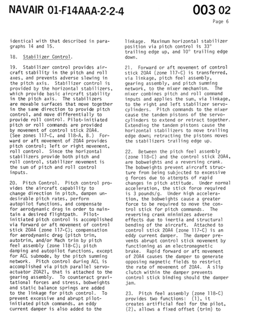
The natops says, "Maximum wing-sweep rate (approximately 15 per second) is adequate for most transient flight conditions; however,wing-sweep rate can be significantly reduced or stalled by negative-g or large positive-g excursions. Sufficient capability has been provided in the system, consistent with the sustained performance capabilities of the aircraft.". https://books.google.com/books?id=J-8cAgAAQBAJ&lpg=PP1&pg=SA1-PA76#v=onepage&q&f=false The older version of the flight manual manual gets more detailed, noting. “Critical performance conditions occur at low linear deceleration/ acceleration of the aircraft under high g’s (split-s or loop maneuvers) and at high linear deceleration/acceleration under low g’s (steep climbs with low thrust or steep dives with maximum thrust). The rate of operation during unsweeping motion exceeds that during sweeping motion at elevated positive load factor conditions. Because of the attachment geometry of the wing sweep actuators, the rate of sweep progressively increases with the wings aft of 50 degrees. Failure of either the combined or flight hydraulic system permits the wings to move at a reduced rate (nominal 3 degrees per second under 1 g conditions).” https://www.avialogs.com/images/photos/docs/694/3368/preview/3368-p131-normal.jpg It seems the maximum sweep rate quoted in the slides, 7.5 deg/sec in level flight, is low. Also since the sustained turn performance of the craft is over 6 g it seems reasonable that the wings should continue to unsweep over 5 g. https://a.disquscdn.com/uploads/mediaembed/images/4046/6189/original.jpg -
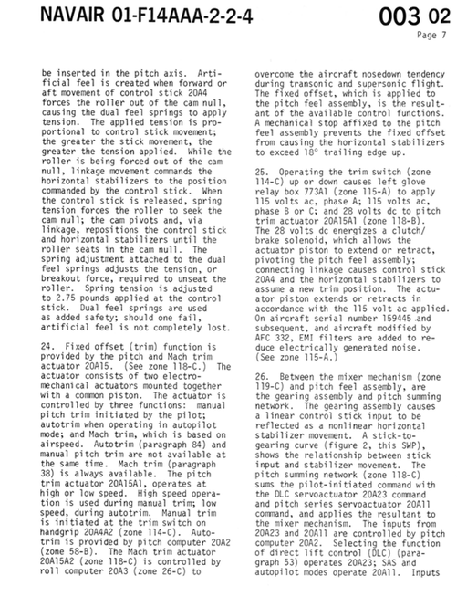
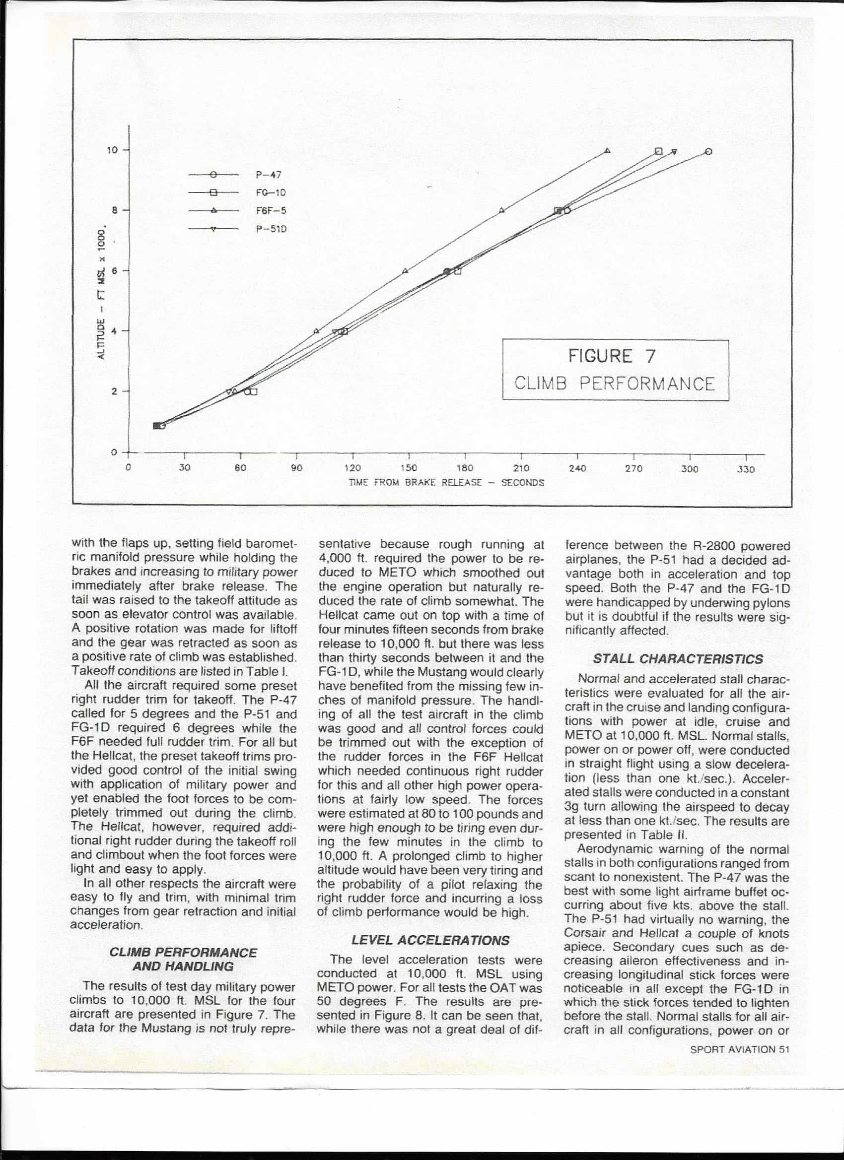
You still haven't read the whole report, The maximum level flight speed for the P-51 with meto settings in these tests was 240 Kias. The engine was run at unspecified manifold pressure below maximum settings using low octane fuel. Vmax in these test indicates the maximum speeds achieved in the tests. Not the absolute maximum speed. This is why I have said corner velocity in these tests is close to the maximum speeds in these tests. The fact that you don't understand what I'm saying or have not taken the time to read the actual report doesn't make what I'm saying subterfuge. You also still don't understand what corner velocity is. 320 is not corner speed. If you pull max g at 320 mph you'll pull 9.4 g's. Since the craft is only rated for 7g you risk breaking it in a 9g turn. Again corner is defined by the where the structural limit meets the lift limit. It is the lowest speed maximum rated g is available. If the structural limit was 9.4 g than corner would be 320 mph or 278 kias. However, it's not, the structural limit is 7g, the corner velocity is 238 kias. You can easily pull 6g at 240 kias and not depart the aircraft or break it. There are also plenty of tests that deal with wing bending of ww2 craft. The spitfire specifically, dealing with aileron reversal issues. You also still don't understand what a one and two circle flow is. You can have multiple passes in both. The term denotes whether the flight path of both aircraft make 1 or 2 circles. Not if they pass each once or twice. I'm happy to discuss this further with you, but at least read the entire report. I it linked in my first post. You should also open another thread to do so and quit cluttering this one up.
-
I would be interested in knowing to what level hook dynamics are modeled. Specifically hook to deck interactions. There's an set of kinematics at play there. If you hit the deck with too much sink rate or at to great of angle, you can over come the hook's damper and the hook will skip. Resulting in a hook skip bolter. There have been some studies written on both hook and wire interactions. Hook dynamics. http://naca.central.cranfield.ac.uk/reports/arc/rm/2980.pdf Wire Dynamics. https://apps.dtic.mil/dtic/tr/fulltext/u2/617788.pdf
-
I’m well aware of what corner speed is. I showed how to calculate it. No I said, the max speed of this aircraft is close to corner speed because the power settings employed in the test. I don’t know where you’re pulling this 320 number from. We can calculate the corner speed with a 6g load limit based on the formula I gave previously. Corner velocity @ 6g is = Square root of 2nmax*W / rho*S*Clmax. Corner velocity @ 6g = 221 Knots=255 mph= Sqrt 6*8900 / (0.0016249 *235 * 2.37) Which is right near the top level speed for the mustang in these tests. No corner would have stayed the same, because corner in the SETP tests is limited by the structural limit, in this case 6g. They didn’t want to risk damaging the airframes so all test were limited to a max of 6g. In all aircraft, corner speed is bound by the lift limit, that is the wing’s ability to produce lift, and the structural limit of the airframe. Based on the DCS P-51 manual the load limit is 7g making corner 275 mph or 238 knots. As 238 knots=275mph.= Sqrt 7*8900 / (0.0016249 *235 * 2.37) 6 g is easy to pull at 240 knots indicated, because 7 g is available at that speed based on the Cl max and wing size. You don’t need any magical prop effect to achieve the performance characteristics your describing. You could hit 6g in a level turn if you’re doing 221 Kias. You just need to have enough thrust to hit these speeds. They did conduct the instantaneous turn tests in a dive. “Instantaneous turn performance was evaluated in a wind-up turns from 10,000 ft.” Page 6 of the report. A wind-up turn is a spiraling descent where the speed and throttle are held constant. While bank angle is increased till max load factor is reached. Speed is maintained as load factor increases by pitching the plane down. By limiting the power available they limited speed of the test. This is why max speed is close to max G in these tests. They limited the power available and max g. If you want to prove something about turn rates and prop effects, show a formula and apply it to these tests, otherwise your presenting nothing but opinion. Both pilots are describing 1 circle radius fights. Radius fights are won by having the smallest turn radius and since turn radius = V^2/Radial G, they are won by the craft that can go the slowest and maintain control. This is why the mustang pilot wins when he drops his flaps and cuts the throttle, his turn radius decreases and he ends up inside the 109’s turning circle. The same is true of the 109 pilot, he even describes shrinking the radius. You’re confusing turn rate with radius, and why and when rate wins and when radius wins fights. In two circle fights, rate wins and since turn rate is = G/Air speed. Thrust and Power are very helpful in winning. The opposite is true in one circle radius fights. Where radius = air speed^2/G. Here speed kills, if your going faster, than your radius is bigger and you drift out in front of your opponent. All the pilot accounts you’ve put forth are describing 1 circle radius fights, which is why they want to go slow. This is biasing your theories. "Turn More" is not an accurate way to describe the motion of the aircraft. Turn more what? More rate? More radius? The math I’ve put forth was all developed well before jet engines and is perfectly suitable for evaluating propeller airplanes. I’ve shown how it accurately predicts the performance characteristics of these craft. You however have showing nothing in the way of independent verifiable math proving your claim. Find an equation which shows the effect of prop width and leverage on turn rate or radius. Further more the basis for your claim that this math is unsuitable to predicted turn performance because these test were not conducted in a dive, is also totally wrong, The instantaneous turn test were conducted in a dive and the speed needed to pull 6 g was 240 kias, that's knots indicated which is = to 276.187 mph not the 320 you're claiming. Go back and read the actual report. The physics are accurately predicting the performance of the aircraft.
-
I went and looked at the actual report and there are few problems with it. Mainly the tests are not conducted at combat or emergency power settings. All power settings were limited to maximum continuous settings. Which for the Mustang is about 1140 hp at the test altitude of 10,000 ft. We can see its about 405 hp less than available than in military settings. Or about 560 less than in War Emergency Power. http://www.wwiiaircraftperformance.org/mustang/P-51D_15342_Level.jpg. The report notes this in the test envelope and limitation section. In all the charts, the power is described as METO, or “Maximum Except for Take Off”. So of course with reduced power settings max G will be closer to maximum speed. This largely invalidates any conclusion you could draw about sustained turn rates based on these tests. As sustained turn rate is a function of specific excess power, Ps. Where Ps =(T-D)V/W. The sustained turn rate line on a doghouse chart is a Ps=0 curve. As the power has been reduced in these tests, the thrust available will be lower and at any given velocity you will have lower sustained turn rate. It has nothing to do with wether the tests are conducted level or diving. It’s a matter of not using enough throttle. The proximity of the maximum speed to the corner speed, or max G available in these test are due to the reduced power settings. Maximum flight speed is defined by the intersection of power required and power available at a given altitude. Since power available in these tests is reduced our top speed is reduced. Since corner velocity is = Square root of 2nmax*W / rho*S*Clmax. It is dependent on speed. Both are functions of power available, in that you can never reach corner velocity without enough power and max speed is a limitation of power available. The relation between Vmax and corner has nothing to do with wether the tests were conducted level or diving, again it’s a matter of how much power was used in the tests. So the sustained turn and acceleration tests in this article are an invalid way to determine flight characteristics. About the only thing of note in this article is the stall testing. I know you’ve talked about the prop as lever, but you’re missing the mark quite a bit. A spinning prop will increase the Cl max of an aircraft. While looking at the stall speeds of the mustang in these flight test it looks like the Cl is quite a bit higher than quoted around the web. Based on the stall speed of 87 knots and converting to imperial units the Cl is 2.37 = 8900 / (1.077 * 0.0016249 * 235 *95.5147^2.). However fly the mustang in game at 8900 lbs at 10,000 feet and it stalls right where it does in these flight tests. The effect is built into the sim. Long story short, trust Yo-Yo, he knows what he’s doing and has better sources than most of us. you can read the whole article here https://ww2aircraft.net/forum/threads/ending-the-argument.47411/. highlights below.
-
The question is kind of a trick. So let’s look at it and break it down. What’s the best way to make a jet go up. What do we mean by go up? if were talking about a purely mathematical perspective of increasing the total lift. Than increasing the velocity of the craft is the most efficient means. As velocity is squared in lift equation. That is Lift force = Coefficent of Lift * Area * .5 * Density * Velocity Squared. So lets look a quick example and see that lift increases linearly as our Cl doubles, while Cl increases exponentially when velocity is doubled. .5 = 1 * 1 * .5 * 1 * 1^2 Our Base Figure 1 = 2 * 1 * .5 * 1 * 1^2 Doubling our Cl, e.g. pulling back on the stick 2 = 1* 1 * .5 * 1 *2^2 Doubling our Velocity, Pushing the throttles up. However I consider this a bit of trick because it ignores some of the more practical aspects of aerodynamics and some edge cases. So what do we mean by best? If we’re talking about the shortest amount of time to reach a desired rate of climb, then pulling the stick back is the best means. It takes way more time and work for an aircraft to double it’s velocity compared to doubling it’s angle of attack by pulling the stick back. Therefore pulling the stick back is the most efficient means to change our rate of climb. The edge case where this breaks down is at the stall. Stall is an increase in the angle of attack which results in a decrease in the lift coefficient. Thus at max Cl the only way to increase your lift is to increase your speed. If you’re low on your approach and pull back to fix you can make the problem worse by stalling the craft. In this case the best way to make the plane go up is to increase the throttle. So the question really does have multiple right answers.
-
By the Numbers: Carrier Landing Geometry & the IFLOLS
Curly replied to Matthew10_28's topic in DCS: F/A-18C
The issue is that in real life the ball will move up and down that within 11 foot space. In the sim it's a binary. So it's; center light on, then when you climb 12 feet, the light above the datam goes on. There is no half ball. While the real device has infinite resolution. The easiest solution would be to subdivide each virtual lenses into 3 sections and allow the tops and bottoms to overlap. The only issue would be that center balls would appear dim compared to half balls. “High Start to In close, come down at the ramp is one of several profile trends leading to a leading hard landings and ramp strikes.” “More ramp strikes occur when the pilot is correcting for a high deviation in-close than for a low deviation. “ “High at the ramp with less than optimum rate of descent can lead to a dangerous long bolter” These statements come from an comprehensive analysis of carrier landing accidents. Part of the reason why this aforementioned conditions tended to result in accidents was that the LSO’s tended to wait till in close to issue glideslope corrections. https://ia800109.us.archive.org/8/items/DTIC_ADA135823/DTIC_ADA135823.pdf Also here is a nice pic of IFLOLS up close, you can see how only a small portion of lens is actually lit. -
By the Numbers: Carrier Landing Geometry & the IFLOLS
Curly replied to Matthew10_28's topic in DCS: F/A-18C
On of the comments I’ve heard repeated from the real pilots is that the DCS Hornet feels draggy or that it’s difficult to energize the ball, IE get the ball moving in response to throttle inputs, during the approach. I’m wondering if this could be related to the implementation of the meatball. If we basically have 12 lights that light up linearly depending on the glideslope, a lot of definition of the system is lost. From the way it sounds, when you’re calling the ball at 3/4’s of a mile, to move the ball up or down you need to move the aircraft vertically 12 feet. Thus when you’re behind the boat adding power, it looks like nothing is happening because the meatball is a kludge. Thus it makes it seem like there is something intrinsically wrong with aircraft, While it’s simply the feedback system causing the perceived issue. This also sheds some light on why rolling out on a high ball tends to lead to more ramp strikes. Since the top ball is lands you so far forward. The amount of sink rate you need drop on the center ball from the top could exceed the craft’s ability to recover. Ie you come in high ball, you have a lot of vertical space to get down, but the craft is configured for max lift, so it really doesn’t want to drop. Thus you have to take a lot of power out to get the ball moving, by the time you’re seeing center ball, it’s all ready to late for recovery, and you ramp strike. You could probably make an interesting case for making the top 2 lights on the IFLOLS instant wave offs like the bottom two.