Curly
-
Posts
169 -
Joined
-
Last visited
Content Type
Profiles
Forums
Events
Everything posted by Curly
-
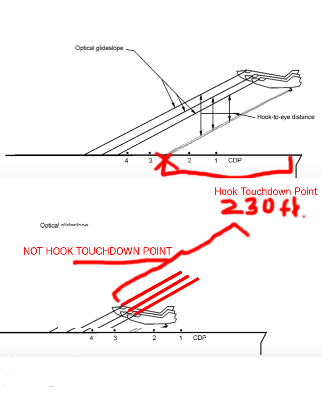
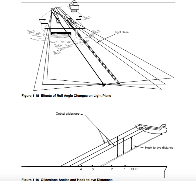
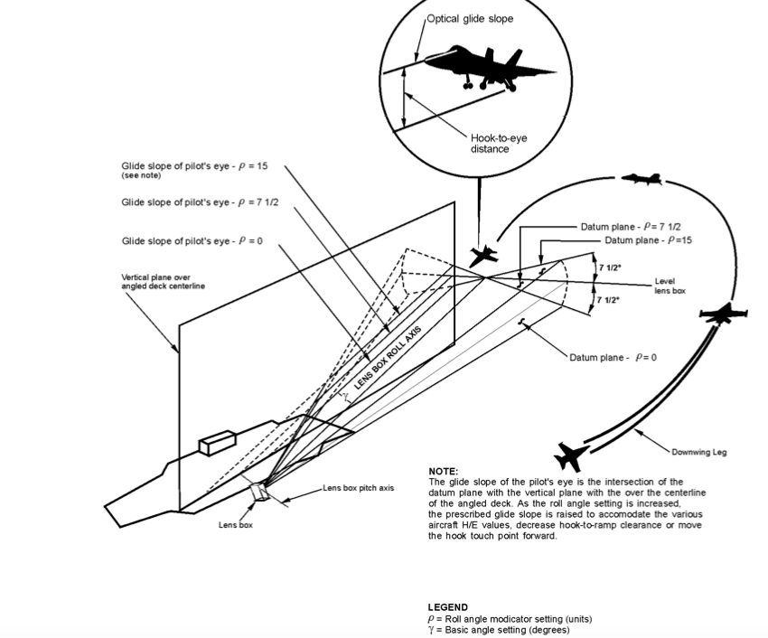
No. The Optical glideslope and hook glideslope have the same angle. The Optical glideslope is just above hook glideslope. This is done by rotating the FLOLS. The optical glide path and hook glide path form parallel lines. Hook to eye distance is a perpendicular line between the hook and optical glidpath. I think your main problem is your hook touchdown point is wrong. You are defining the hook touchdown point as a spot along the optical glide path. This is messing with all of your geometry. The hook touchdown point is simply measured from the ramp forward. In the case of Nimitz class, the hook touchdown point is 230 feet forward of the ramp.

-
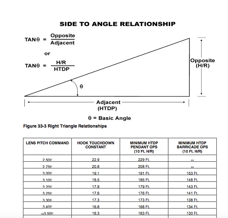
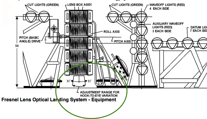
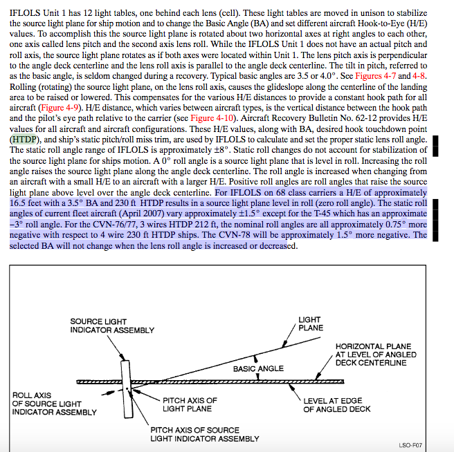
A few things. Your measurement of the Hook to ramp clearance as a sanity check is off. You’re measuring from the bottom of the round down. The measurement should be taken further forward of the rundown, where the deck levels. In doing so, you will have less hook to ramp clearance. Also I think your a bit confused on hook touch down point. I think your measuring the hypotenuse as the hook touch down point. The Hook Touchdown Point (HTDP) is measured from the ramp forward,it’s the adjacent angle in the glideslope right triangle . However there is another flaw beyond these points where some error is coming from. You’re not compensating the light assembly for hook to eye distance. The entire IFLOLS assembly rotates in order to raise the beam of light above the deck. The net effect moves the optical glide slope forward. When you project the glide slope straight out of the lens 3.5 degrees without raising to compensate you will always end up with to little hook to ramp and early engagements. It would be like a PAPI light placed 16 feet below the runway. The way you built your glide slope with cross checking light heights is also off. Since your hook to ramp is off your light heights / glideslope ends up shallower because your hook touch down point is to far aft. Which is why it ends up with the hook on the 2 wire. Hook to ramp clearance is calculated as the Tan of the IFLOLS angle = hook to ramp / hook touchdown point. This is done to provide a safety margin which can quickly be adjusted and calculated as conditions change. As first sanity I would check the dimensions of the carrier layout. The model of the carrier could be off in a few ways that would effect your modeling. The wire distance from the ramp could be wrong. The height of the IFLOLS could be lower than expected. The LSO NATOPS provides and interesting way to try and validate the dimensions too. According to page 4-9. “A H/E of approximately 16.5 feet with a 3.5 BA and 230 HTDP, results in a source light plane level in roll (zero roll angle)” I really liked the video and hope you keep it, the community needs more of this stuff.
-
Are you accounting for hook to eye distance? The optical glide path needs to be moved up to account for the distance between the the pilot's eye and the hook. In the Hornet's case it's 16.7 feet at on speed AOA. If you're using 220 from the ramp, half the distance between the 2 and 3 wire, as your hook touchdown point you could also be running into an issue too. Not accounting for a hook to eye and setting the hook touchdown point at 220 feet means the hook will be touching down at 203 feet of the ramp, 6 feet short of the 2 wire. Which would account for catching a 2 wire by several feet. Just as an FYI the hook touchdown point for Nimitz class should be 230 feet, according to the pertinent aircraft recovery bulletins. I'm not sure how they set up IFLOLS in game or even if the distance between the wires is correct, all of which could be messing with your endeavor. Oh the optical focal point for the lenses is either 240 or 140 feet beyond IFLOLS. (EDIT) However after looking at this again I think you just mean the distance to the IFLOLS lights. Which should be 486 from the ramp in a CV 68. Also, are you accounting for wind over deck in caluctions. As wind over deck increases the actual glide slope decreases. This could also could be causing shorting the 3 wire.
-
Your attitude is entitled and self righteous. There are a handful of real experts that choose to share on the forums. When they do show up, every arm chair expert pops out of the woodwork when they don’t like the way the information is presented. Responses like your’s ensures that there will be less interaction between subject matter experts and the community. Why would anyone want to put with this? Designing helicopter events and running a server doesn’t give you license to bray like a jackass. You have offered nothing substantive in your replys. If you want to see something different, try being constructive and specific in your requests. The only outcome of your response is, less interaction with subject matter experts. You're not a firebrand speaking truth to power, you're a petulant child who didn't get his bottle.
-
This is the technique for demonstrating spin characteristics with the 10.7 OFP The following spin demonstration procedure is recommended for v10.7 Automatic Spin Recovery Mode Demonstration: 1) Stabilize wings level, 150 KCAS and 35,000 feet. 2) Slowly reduce both throttles to IDLE. 3) Set 15 to 20 degree pitch attitude and hold. 4) When AOA tone is present (approximately 35 AOA) smoothly apply full aft stick while noting heading or ground reference. 5) Firmly hold full aft stick and smoothly increase thrust on left/right engine to MAX with opposite engine at IDLE. Simultaneously apply full lateral stick and rudder pedal (full pirouette control inputs) into the direction of the throttle at IDLE. 6) Hold the control inputs for 1.5 turns while counting every half turn looking outside the cockpit. 7) After 1.5 turns, neutralize control stick and rudder pedal inputs - release the control stick and take feet off the rudders. 8) Automatic Spin Mode logic should activate within 1/4 turn. 9) Note the spin arrows, altitude, AOA, airspeed, and yaw rate. 10) Proceed with NATOPS spin recovery procedure: apply lateral stick in the direction of the spin arrows. 11) Continue to look outside the cockpit. 12) When yaw rate ceases, neutralize the lateral stick. 13) Note when the spin arrows disappear. 14) Bring both throttles to IDLE and complete NATOPS Out-of-Control Recovery procedures by waiting for AOA/yaw tones to be removed, side- forces to be subsided, and aircraft to increase through 180 KCAS prior to recovering from the nose low attitude. From https://trace.tennessee.edu/cgi/viewcontent.cgi?referer=https://www.google.com/&httpsredir=1&article=3738&context=utk_gradthes
-
The Hornet's sustained turn rate is anywhere from 2 to 4 degrees less than that f-16's, depending on weight and load out. In EM diagrams the sustained turn rate line is know as the Ps zero line. Ps 0 indicates where in the flight envelope the craft can maneuver without losing energy. Ps is calculated as Ps = V(T/W-D/W). When Ps is positive the craft can accelerate, climb and or increase G without losing airpseed. Looking at the charts. At mach .85 the hornet pulls 10.2 degrees per second which equates to about 5 G. The F-16 at mach .85 pulls 14. degrees per second which equates to about 7.2 G. Clearly the Viper has a turning rate advantage. Though much of that advantage is due to the weight and increased drag of this load. It's three bags, Sparrows and Sidewinders. Which increases the drag and weight of the Hornet. So it's not really an apples to apples comparison. A more comparable comparison to the F-16 block 15 is the Hornet in the light configuration. In this config, the Hornet pulls 12.5 degrees per second, according to the Elements of Power sources. Based on the airframe and the other chart, We can assume this will be around mach .85. Thus we're making this turn at about 6 G. The amount of G is important because turn rate =G / V. Going back to our discussion on Ps, recall Ps = V(T/W-D/W). The reason why the Hornet doesn't have the same sustain turn rate as the F-16 despite having more thrust is because it's heavier and generates more drag. Things even out with later blocks of the F-16 as it got heavier and more dragy. Take this Em chart for what it's worth, there isn't much background info accompanying it. As for Hornet charts this one isn't bad. It's the same loadout as the 10.2 degree Hornet in the elements of power blog chart. In regards to sources. Like your F-16 EM chart, many of the aircraft EM charts on the web come from "Weapon Symposium "Fighter Performance" Handbook, Circa 1986 by Pawloski. This was handout give to participants of a General Dynamics conference. All these charts have similar visual styles, like this mirage one. http://2.bp.blogspot.com/-eiImrT1REak/UW4c4oeGpvI/AAAAAAAACRg/zfu0jsNC-3A/s1600/Mirage+2000+at+15k.jpg The Elements of power blog also uses this reference to create the charts above. So we get a pretty comparable comparison.
-
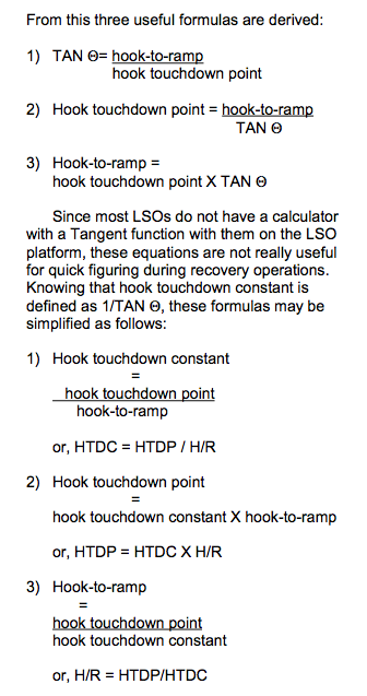
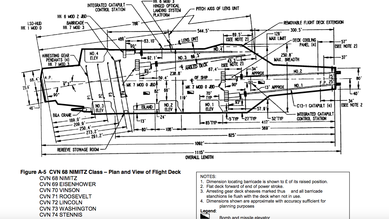
To ensure adequate hook to ramp clearance Hook to ramp refers to the distance from the tip of the hook to aft section of the carrier runway. Safety requirements say it should be no less than 10 feet. If hook to ramp distance is less than 10 feet there is a large risk of inadvertent engagement. Say if the ship heaves, for example. Hook to ramp distance is primarily a function of the distance from the hook touchdown to the ramp. Hook to ramp distance can be adjusted by changing the basic angle of meatball. Lets look an actual carrier recovery bulletin used by LSO's. CV 62 Independence stands out. The first thing to note about her is, that she can't recover aircraft using a 3 degree glide slope because the hook to ramp distance is less than 10 feet. This is because the three wire is located to close to the ramp. Since it’s based on right triangles, we can mathematically prove it. CV 62 Hook touchdown point = 185 feet forward of the ramp Tan of 3.0 = Hook to Ramp clearance /185 (Hook Touchdown distance from ramp.) Hook to ramp = 9.69 Thus you can never safely land aircraft via a 3 degree glide slope on the Independence. To use a 3 degree glide slope on any carrier the hook touchdown point needs to be at least 191 feet forward of the ramp. As Tan 3 = 10.009/191. The Saratoga and the Forrestal are even worse, their touchdown point is only 178 feet from the stern. The main concern with AOA on the approach is Hook to Eye Distance. Hook to Eye, is the distance from the pilots head to end of the arrestor hook. If we didn’t take this distance into account the hook would always land short of the target wire. Hook to Eye varies with each aircraft. Again lets look at a a real Aircraft Recovery Bulletin. As we can see all aircraft have different hook to eye distances. Thus the meatball has to be adjusted for various aircraft types. In order to ensure each aircraft's tail hook lands half way between the 2 and 3 wire, on 4 wire boats. So if hook to ramp clearance calls for a 3.5 degree glide slope, The meatball will set to angle of 3.5 and then optical tuchdown point moved forward 16.70 feet if we’re recovering Hornets. So that the hook path lands half way between the 2 and 3 wire.
-
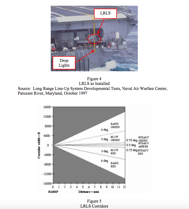
You're not, the system described is the Long Range Line-up System or LRLS. It has been superseded by the Long Range Laser Line-up System LRLLS. Which is visible up to 10 miles away from the carrier. See also: page 24 of. https://www.cnatra.navy.mil/local/docs/pat-pubs/P-816.pdf
-
Per the 570-100 and a NASA report on the FCS. Stick force gradient increases 22 degrees of AOA providing the pilot feedback that he is now commanding AOA. In the Not Auto Flaps Up mode (Powered Approach mode). The FCS increases stick forces at 12 degrees of AOA to let the pilot know he is approaching stall. When the FCS detects the AOA increasing over limits, it sends a signal to feel actuator which causes the actuator to tighten a spring. Thus increasing the forces need to pull the stick back. A force feedback joystick has the same capabilities. That is changes of stick forces on the fly. It's allready implemented on other aircraft. Put a P-51 in loop with a FFB stick, and it will be stiffer as you enter the loop at high speed, and as you slow and the load on the elevator decreases, the stick feel becomes loser. If you haven't it tried it, I highly recommend it. You can usually get a FFB stick off Ebay for 50$ ish us. I think it's worth every penny. http://www.dtic.mil/dtic/tr/fulltext/u2/p002709.pdf The stick force to AOA is on Page 3 of the PDF. That doc gives a nice overview and has some other interesting graphs. If you're looking for some more detailed info on the FCS the 570-100 is good, the NASA technical memo regarding the construction of their simulation. It also has some great technical info on the FCS, including gains schedules, ect . Unfortunately it only describes the Auto Flaps Up operation. https://ntrs.nasa.gov/archive/nasa/casi.ntrs.nasa.gov/19920024293.pdf AIAA also has a paper comparing the Navy's Hornet simulator to the real thing. It also probably has some very useful info, though it's behind a paywall https://arc.aiaa.org/doi/abs/10.2514/6.1997-3667 The primary source material for info on the FCS would be the McDonnell Douglas reports, specifically MDC A4107.
-
Using "throttle for GS and stick for AOA" when landing
Curly replied to LJQCN101's topic in DCS: F/A-18C
While flying the backside technique you apply corrections just as you would in a conventional approach. If you encounter winds you don't wait for aircraft to settle either, you actively aviate. It's just your corrections are different. What is the corrective action when encountering a downburst. It's not just pitch. You apply full power, because pitch alone will kill you. The backside techniques work just as well and are safer than conventional corrections for shear. Since the ability to fly a specific glide slope is determined by the power available. During a downburst the power requirement goes up because an external force is acting downwards on the craft. Using the backside technique of adding power for glide slope fixes this. The problem with adding pitch is you trigger a dynamic response. That can exacerbate your primary issue, rapidly increasing descent rate. Lets say there is a down burst and you pull back on the stick to counter. You increase the AOA and therefore the lift coefficient, problem solved right? Not really because you've increased drag and made your L/D ratio worse. Your now losing speed. Since lift = .5 * Cl * air density * velocity^2 * area, We end up with less lift, thus increasing our descent rate. Pitching further compounds the problem we slow further, losing more lift and increasing the descent rate. If we excessively pitch while adding power, your responses are nulling each other out and you don't net out a positive response that will halt the excessive sink rate.. You have more power but less lift, it's easy to doom the aircraft in this manner. That's why the only pitching you should be doing is to keep aircraft the aircraft's angle of attack stable. As the wind will be pushing the nose down. The backside technique is safer in shear conditions because, you are responding to forces acting on the aircraft which are disrupting the flight path with opposite opposing forces immediately, rather than responding with actions that trigger a dynamic state which may or may not help you. It's why the navy trains pilots to respond to shear the same in a way in a turbo prop as in Hornet. http://www.t6bdriver.com/uploads/6/4/7/7/64775059/c3402_briefing_guide_1542.166b.pdf -
Using "throttle for GS and stick for AOA" when landing
Curly replied to LJQCN101's topic in DCS: F/A-18C
Auto Throttle is a powered approach compensator. It's a sort of a fly by wire system. It will attempt to hold a specific angle of attack and has it's own set of logic. When engaged you would fly it conventionally, that is stick for glide slope. Usually what happens when you pull back on the stick is that the engines throttle up. So the aircraft flys the backside technique for you. So if you're using the auto throttle and trim it's mostly correct. If you're flying the VRS Superbug or the default FSX accel Hornet. Neither has the fly by wire logic implemented for the powered approach mode. So they both handle unrealistically around the boat. VRS's work around is to use the auto throttles. I'm not sure if there is currently a version of Hornet that implements the Powered Approach mode correctly. -
Using "throttle for GS and stick for AOA" when landing
Curly replied to LJQCN101's topic in DCS: F/A-18C
Pitch for AOA and throttle for glide slope is also know as the backside technique. It predates fly by wire control systems. The backside technique is first recommend by the Naval Safety Center in June of 1959. NASA had looked into earlier of that year. The Flight path angle is = D/L - T/W + dV/dt/g Thereby flight path angle is a function of lift to drag ratio at approach speed, thrust to weight ratio and the rate change of airspeed. It was found in a lot of aircraft configurations that the lift to drag ratio decreases at high lift coefficients. Total drag increases with decreasing airspeed, this is as the region of reverse command or the backside of the drag curve. The speed for minimum drag will also be the speed for neutral speed stability. At speeds higher than that for minimum drag, the airplane will return to the trim speed following a disturbance. At lower speeds following a disturbance the aircraft will diverge in speed. So what happens when you pitch up to correct for a low glide slope. First you change the L/D and add more drag thus slowing the aircraft down. You’re now on the backside of the drag curve. As the craft slows, your sink rate increases. You’ve also slowed the craft to where it’s no longer stable. Now you’re sinking and slowing. If we’re pitching to fix glide slope, at this point we would pitch up further to correct for our increased sink rate… you’re in a death spiral. Each increase in pitch compounds your problem, as L/D gets worse and you slow down more and drop at a faster rate. You pull back trying to fix your problem and stall. If you’re flying a turbofan with a engine lag, like an early jet or an F-14, or a aircraft with a low thrust to weight ratio, you may be out of options. The engines won’t spool in time to save you. Even if you manage to stay on the throttles to fix your speed problem and avoid a stall, you’ve put the aircraft into a state where making a precision landing will be extremely difficult. Remember what said about speed stability, Well because we pitched up and slowed down our speed stability is gone and the now the aircraft is a a phugoid. The task of controlling the approach with any precision is now orders of magnitude more difficult as the craft pitches about while changing speed. The key aspect to understanding why this technique is used is often overlooked and relates to stability. The start of this technique is predicated up on the fact that we are trimmed for level flight before turning on final. If the aircraft is in a steady state, we say that all the forces acting upon it are in equilibrium. Thus Our speed = 17.2* Sqrt Gross Weight / Wing Surface / Lift Coefficient. Or 17.2 * Sqrt of Wing Loading / Lift Coefficent So if we pull back on the stick, we increase the lift coefficient on the tail, and increase the total lift coefficient. Thus reducing our speed. Hence we pitch for speed. In a steady state our rate of climb or descent in feet per minute, is = 33,000(Power available - Power Required for level flight / Gross Weight) So our sink and climb rate is a function of excess power. Since we can modulate the amount of excess power with the throttle and maintain speed stability, we use the throttle to control glide slope. Really the best guides to understanding why this technique is used are the primary sources. Aviation for Naval Aviators offers a in-depth expiation in chapter 6. https://www.faa.gov/regulations_policies/handbooks_manuals/aviation/media/00-80T-80.pdf The early NASA document on landing approach speeds does a nice job of explaining as well. https://ntrs.nasa.gov/archive/nasa/casi.ntrs.nasa.gov/19980232089.pdf And the review on powered approach speeds criteria from Nav Air provides a history of the development of the backside technique in chapter 2. Though the whole thing is worth the read. http://www.dept.aoe.vt.edu/~durham/2002-71.pdf
-
Thrustmaster Warthog combined joystick problem
Curly replied to MadMonty's topic in PC Hardware and Related Software
I had a similar issue, I found a solution on the BMS forums. I'll paste it here since you have to register to view their boards. Issue: The Teamspeak Joystick and Gamepad Addon prevents Thrustmaster's target software from working properly. The teamspeak addon prevents target from hiding the physical devices from windows, thus preventing target to function properly, even after Teamspeak is closed. Solutions: 1, By removing the Gamepad / Joystick addon from teamspeak target works properly. 2, Hard reboot the system start target and run your profile before opening teamspeak. Both solutions have been tested effective on the latest version of target across multiple systems. Background Thurstmaster Target Principles of Operation: Target functions by creating a virtual control and hiding the physical devices (joysticks) from the system. This allows the user to program the joystick to any number of virtual functions, keyboard commands, axis modification, ect. Since the Teamspeak Joystick and Game Pad addon prevents windows from hiding the physical devices, a profile will not work properly. You end up with phantom joystick buttons, ect. It fundamentally breaks target. The problem continues even when Teamspeak is closed. I don't think the joystick addon ever fully shuts itself down when target is closed. Disabling the addon doesn't seem to help either. The problems began to appear a few patches ago when the addon was bundled with the basic install. It got worse with the latest release. How to delete the Teamspeak Joystick Addon Open Teamspeak, select tools->Options->addons (it's on the left sidebar), Select the Joystick and Game Pad addon and delete it. Restart teamspeak and run your profile. If you need target and joystick push to talk, I would recommend Discord, it functions flawlessly with target. -
Using "throttle for GS and stick for AOA" when landing
Curly replied to LJQCN101's topic in DCS: F/A-18C
Hook to ramp refers to the distance from the tip of the hook to aft section of the carrier runway. Safety requirements say it should be no less than 10 feet. If hook to ramp distance is less than 10 feet there is a large risk of inadvertent engagement. Say if the ship heaves, for example. Hook to ramp distance is primarily a function of the distance from the hook touchdown to the ramp. Hook to ramp distance can be adjusted by changing the basic angle of meatball. Lets look an actual carrier recovery bulletin used by LSO's. CV 62 Independence stands out. The first thing to note about her is, that she can't recover aircraft using a 3 degree glide slope because the hook to ramp distance is less than 10 feet. This is because the three wire is located to close to the ramp. Since it’s based on right triangles, we can mathematically prove it. CV 62 Hook touchdown point = 185 feet forward of the ramp Tan of 3.0 = Hook to Ramp clearance /185 (Hook Touchdown distance from ramp.) Hook to ramp = 9.69 Thus you can never safely land aircraft via a 3 degree glide slope on the Independence. To use a 3 degree glide slope on any carrier the hook touchdown point needs to be at least 191 feet forward of the ramp. As Tan 3 = 10.009/191. The Saratoga and the Forrestal are even worse, their touchdown point is only 178 feet from the stern. The main concern with AOA on the approach is Hook to Eye Distance. Hook to Eye, is the distance from the pilots head to end of the arrestor hook. If we didn’t take this distance into account the hook would always land short of the target wire. Hook to Eye varies with each aircraft. Again lets look at a a real Aircraft Recovery Bulletin. As we can see all aircraft have different hook to eye distances. Thus the meatball has to be adjusted for various aircraft types. In order to ensure each aircraft's tail hook lands half way between the 2 and 3 wire, on 4 wire boats. The meatball’s angle is the basic angle + adjustment for hook to eye. So if hook to ramp clearance calls for a 3.5 degree glide slope, The meatball will set to angle of 3.5 and then moved up 16.70 feet if we’re recovering Hornets. So our actual glide slope is greater than 3.5. What happens when your AOA is off is that hook to eye changes. Thus it compounds any flight path errors and leads to the hook either catching to soon or later.
-
Cool, thanks for all your work on this. I really dig the project. The A-4 is a really interesting aircraft. That NASA doc I linked is a pretty good read too. Full scale wind tunnel tests, to evaluate various battle damage on the polars. They actually had the Air force shoot two different sets of wings with 25mm and 30mm guns, to asses the effects on the craft. There is even a polar for the approach config.
-
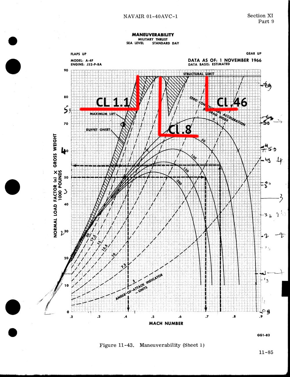
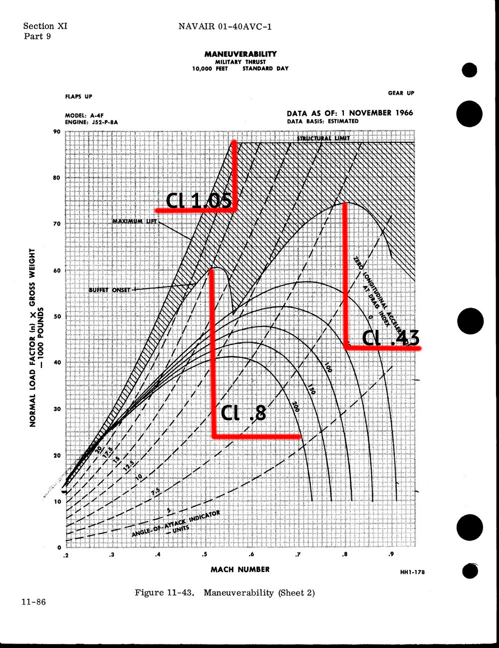
Based on your interpretation of the charts; at 10,000 ft the A-4 can hit a load factor of 87,500 lbs at mach .56. This would require a Cl of 1.05. Roughly 25% above where NASA places it. If you also look at the sea level performance charts for the A-4. The slowest velocity you can hit the structural limit at is mach .53. With a wing area of 260 feet, that put’s the Cl at .8. This matches the Cl max from NASA. This this leads me to believe, the area in the “maximum lift” section, are not part of the actual flight envelope, but possibly the theoretical limits of the 2-d airfoil. There this other good evidence to this effect too. For example, the corner velocity for the 10,000 ft chart on the “buffet onset” gives a load of 60,000 lbs, at Mach .51, at 10,000ft. With a wing area of 260^2 ft, the Cl needed to hit the load factor, for a wing of this size comes out to .8. Again it’s same NASA found for Cl Max with a full scale wind test of an A-4. Based on your charts, I would say your Cl max is to high you should tune to target the buffet onset. If you try and adjust the Cl to hit “maximum lift” limit up at the slower speeds, you’ll need more Cl to hit those structural limits, which is counter-intuitive. I also would like to try and head off any discussion about slats. At the speed these instantaneous turns are being flown, the slats would not be deployed. The slats on the A-4 were like those on the Bf-109, on rollers and held up by the on coming airflow. At corner velocity, mach .5 they will be up. It really doesn’t take much speed to hold them up. They come most of time before the catapult shot is over.
-
The conversion for AOA to units in the eagle is AoA[units] = 0.7728*AoA[Degrees] + 12.22 I saw a max of 41 indicated on the hud giving a true a of 37 Degrees. The craft looked deeply stalled at that point at around 3:33. The craft is stalled well before that earlier in the video. At around 3:24 it's at 33 units of Alpha and stalled. The ability to generate more alpha in the stall is more likely the result of the Eagle greater than 1:1 thrust to weight ratio and excellent pitch authority due to it's large flight control surfaces. You are just able to slowly rotate the aircraft while the huge engines rocket you up. Where the craft does actually stall it looks pretty much on the numbers from the flight manual http://www.avialogs.com/viewer/avialogs-documentviewer.php?id=3704 page 247.
-
TTG is the most likely determinate of wether the missile lofts or not. High loft energy management ascent profiles can lead to a miss due time to climb, especially in a tail chase scenario. http://ac.els-cdn.com/S2405896316301197/1-s2.0-S2405896316301197-main.pdf?_tid=ad09ee42-6fec-11e7-b48d-00000aacb35d&acdnat=1500844976_b7e03651cbf08601fa7a225b3c6a8320 It seems like the DCS missiles only have two guidance phases at the moment, boost and terminal. Some midcourse guidance laws designed to manage energy would probably lead to more realistic results. Solutions are publicly available ranging in complexity from keeping the missile flying at L/D max To something more complex like optimal control theory or even more intricate like Singular Perturbation. The missile probably should only go P/N with in the seeker range in the terminal phase.
-
Here's a little more detailed timeline of what occurs during an ACLS approach. It comes from ACLS installation certification manual. http://www.dtic.mil/dtic/tr/fulltext/u2/a118181.pdf "In a Mode I approach, the computer-generated flight commands are transmitted through the data link to the aircraft, where they are coupled into the Automatic Flight Control System (AFCS). Flight-path-error data are also transmitted to the aircraft for cockpit displays to allow the pilot to monitor the system. The AFCS, controlled by the ACLS, keeps the aircraft on the designated flight path and glideslope while the autothrottle (APC) main- tains the approach angle of attack by controlling the throttle setting. Approximately 12 seconds before touch down, the ACLF generates and transmits deck motion compensation (DMC) commands to the aircraft. These DMC commands are introduced over a 2-second span at the 12-second mark to control the vertical position of the aircraft so that the aircraft will be in phase with the ship's moving flight deck. In the final seconds of the approach, normally 6 to 10 seconds from touchdown, additional ramp input pitch commands may be applied to assist the aircraft through the aircraft carrier air wake or burble. These ramp commands are tailored to each specific ship and aircraft type during a certification and are based on the aircraft's measured ACLS performance through the burble."
-
Will hook and deck interactions be fully modeled, i.e. hook skip bolters. The British commissioned a very detailed paper on the problem, back when they were still in flattop biz. http://naca.central.cranfield.ac.uk/reports/arc/rm/2980.pdf It's interesting how these interactions still remain a major design issue. https://theaviationist.com/2012/01/09/f-35c-hook-problems/
-
I think it should all be automated. Most of the math is based around the relationship of right triangles. So It's not very computationally taxing. I'm not sure most people would have the practical knowledge to setup a FLOLS system which would simulate a realistic and safe approach. For instance, the Saratoga can't safely land aircraft using a 3 degree glide slope, while her sister ship the Ranger is cleared to, and that's just based on the hook touchdown point. Once you get into computing base angle vs effective glide slope and hook to ramp clearance; my faith in peoples ablity to calibrate the system correctly is nil. Also even if you had a virtual LSO station, most of the changes to base angle, hook tuchdown point and roll angle (hook to eye) are not done at the LSO station but in Pri Fly by the Air Boss.
-
Is this system simulating the control equations of the AN/SPN-42? http://www.dtic.mil/dtic/tr/fulltext/u2/a118181.pdf Pages 163-169 Or Are you using a form of proportional navigation to guide the craft to a target point on the carrier deck?
-
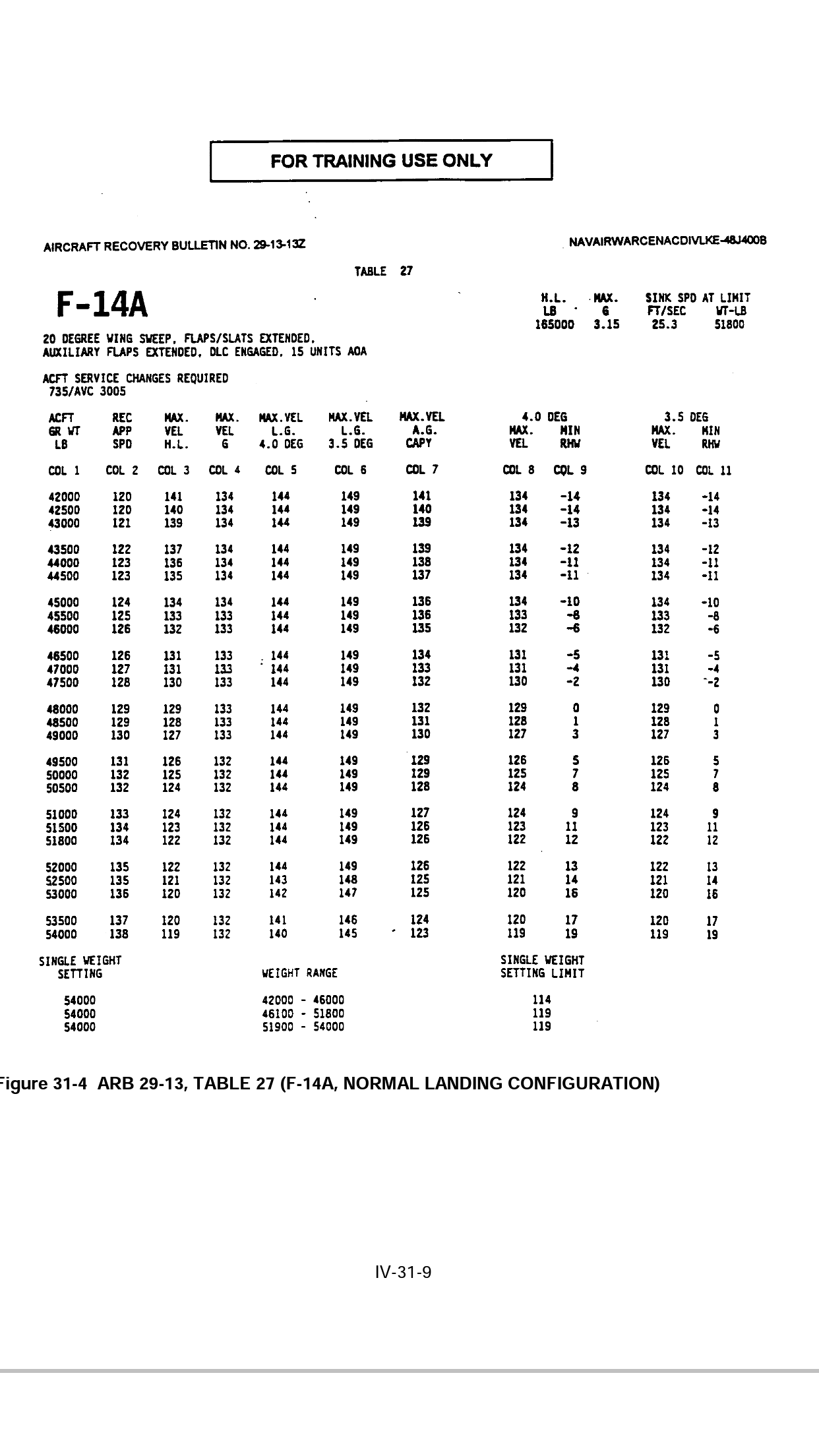
Just for fun some aircraft recovery bulletins with F-14 info.
-
The conversion for AOA units to angles in the Tomcat is AoA units = 1.0989 *(AoA true + 3.01) Which gives us a landing AoA of 10.64. Not out of the realm of possibilities given that the Hornet approach alpha is about 8 degrees. A quick shorthand to convert units of alpha to degrees for the F-14 below Mach .4 is to subtract 5 from units to get the angle in degrees. This only works for the f-14, all other aircraft use different equations to convert AoA units to degrees. http://www.dtic.mil/dtic/tr/fulltext/u2/a243109.pdf So for a 3.5 degree glideslope at 10 alpha the TvV should be on 3.5 line of the hud, meaning the water line should be 6.5 degrees up.
-
I’ll try to clarify a bit. It’s incorrect to draw the conclusion that GAU-8 will fire 80% of it’s rounds through a 6 meter circle at 1,200m, based on the rating of 5 mil 80%. The equation and application in “Predicted Effect of Projectile Dispersion “ shows that the area and percentage in the rating 5 mil 80% is based on the variance from the mean aim point. Since we have the guns rating we can figure out the standard deviation. In the case of the GAU-8 the standard deviation of where the rounds impact around the aim point is 1.3932 mils. This is a much tighter grouping than 80% of the rounds through a 6 meter circle. That grouping would actually be 17.94 mils 80%, as the standard deviation would equal 5. The shell table value for Da0 is .0017. Which could be the standard deviation based on the misunderstood nature of the rating 5 mils 80%. If it were mis-typed in error by 1 decimal, or obfuscated by a magnitude of 10 per ED’s contract with the DoD. Though I don't think this is the case because the grouping shrinks when Da0 gets smaller. So It leads us back to the question what is Da0? I have done some informal testing with Da0 set to .000000307257 and the results seem to be more in line with results in the damage assessment document.