Curly
-
Posts
169 -
Joined
-
Last visited
Content Type
Profiles
Forums
Events
Everything posted by Curly
-
It's both. The bullets have to much drag and the barrel heating penalties (accuracy and velocity drop) are to high. However the MiG-15 also has issues with it's armament. The 23mm HEI shells don't fire. So the 23mm cannon only has half the ammo. 40 rounds not the 80 it's supposed to have. Also, the 23 mm AP rounds have their caliber set to 37 mm. Which I assume was a hack to get the 23 mm cannon to work.
-
fixed 23mm API Shell Has It's Caliber Set to 37mm In the Code.
Curly replied to Curly's topic in Bugs and Problems
I also noticed that the 23 MM HEI shells don't seem to be firing. Perhaps because their caliber is set to 23mm and there is some type of engine limit that prevents aircraft from having multiple caliber weapons. I tested it by placing a static on the runway and firing the 23mm guns only. No 23mm HEI shells show up in the logs. Only API Rounds.trk The 23 mm HEI should show up in the logs as user_name = "23mm HEI T", based on the shell table entry. The API do appear in the logs. They match their reporting name as defined in the shell table. user_name = "23mm API" However the 37 MM HEI shells seem to be working. Tested by firing on a static with only the 37mm firing. The HEI rounds show up in the logs. 37 MM API and HE Rounds.trk It may be, that the 23 mm shells need to have their caliber also set to 37mm for them to work too. Right now the 23 mm HEI have their caliber set to 23mm. In the files it looks like this. AP_cap_caliber = 23, Da0 = 0.0007, Da1 = 0, Dv0 = 0.005, _file = "./CoreMods/aircraft/MiG-15bis/MiG-15bis.lua", _origin = "MiG-15bis AI by Eagle Dynamics", _unique_resource_name = "weapons.shells.NR23_23x115_HEI_T", caliber = 23, -
fixed 23mm API Shell Has It's Caliber Set to 37mm In the Code.
Curly posted a topic in Bugs and Problems
One of the shells that MIG 15 uses is the "NR23_23x115_API.LUA". Has the caliber is set to 37, not 23. Not sure if it effects any of the modeling. Just thought I would bring it your attention. First in the shell table. weapons_table/weapons/shells/NR23_23x115_API.lua NR23_23x115_API.lua ["weapons_table"]["weapons"]["shells"]["NR23_23x115_API"] = { AP_cap_caliber = 37, Da0 = 0.0007, Da1 = 0, Dv0 = 0.005, _file = "./CoreMods/aircraft/MiG-15bis/MiG-15bis.lua", _origin = "MiG-15bis AI by Eagle Dynamics", _unique_resource_name = "weapons.shells.NR23_23x115_API", caliber = 37, Then in db/Units/Planes/Plane/MiG-15bis.lua }, <6>{ AP_cap_caliber = 37, Da0 = 0.0007, Da1 = 0, Dv0 = 0.005, _file = "./CoreMods/aircraft/MiG-15bis/MiG-15bis.lua", _origin = "MiG-15bis AI by Eagle Dynamics", _unique_resource_name = "weapons.shells.NR23_23x115_API", caliber = 37, Also in Eagle Dynamics\DCS World\CoreMods\aircraft\MiG-15bis\MiG-15bis.lua declare_weapon({category = CAT_SHELLS,name = "NR23_23x115_API", user_name = _("NR23_23x115_API"), model_name = "tracer_bullet_crimson", v0 = 680, Dv0 = 0.0050, Da0 = 0.0007, Da1 = 0.0, mass = 0.199, round_mass = 0.340+0.071, -- round + link cartridge_mass = 0.0, -- 0.111+0.071, cartridges are ejected explosive = 0.000, life_time = 5.0, caliber = 37.0, -
The correct Muzzle Velocity for the M2 AP should be 2,840 FPS, 865 MPS. The reduction in accuracy and velocity due to barrel heating should be reduced to reflect the qualities described in weapons manuals. Possibly replaced with either a cook off event or a jam. With regards to the correct muzzle velocity for these rounds. The manual for the AN-M2 and AN-M3 both give the same muzzle velocity for the various rounds. From the 1947 version of the AN-M2 manual, TM9-225 1947. http://www.nj7p.org/Manuals/PDFs/Military/TM 9-225 28-Jan-47 Google.pdf The AN-M3’s ammo table and muzzle velocity from the 1955 version of the AN-M3 manual, TM 9-2190 Both manuals also refer to the same document, which provides the ballistic profile of the ammunition. Ballistic Data Performance of Ammunition TM-9-1907 https://ia800909.us.archive.org/22/items/TM91907BalisticDataPreformaceOfAmmunition/TM%209-1907%20Balistic%20Data%20Preformace%20of%20Ammunition.pdf A cleaner version of this chart is available in https://cgsc.contentdm.oclc.org/digital/collection/p4013coll8/id/2374 TM 9-1907 also gives the muzzle velocity as 2,835 FPS. So this appears to be the correct muzzle velocity for M2 AP round. However, in some of the literature, the muzzle velocity is quoted as 2700 fps. This lower velocity 2700 fps comes from 1940 version of the AN-M2 manual -TM 9-225 https://ia601208.us.archive.org/21/items/TM9-225/TM9-225.pdf It gives the velocity of the M1 AP Round as 2700 fps at 78 feet. Then in 1942, the revised TM 9-225 manual states muzzle velocity for the M2 AP round is 2900 fps. https://digital.library.unt.edu/ark:/67531/metadc29988/m1/50/ It appears the correct muzzle velocity for the M2 AP rounds is 2840 FPS, As the most current sources list it. On burst length. The manuals for both guns, indicate barrel heat affects 4 aspects of the guns performance, velocity, accuracy, stoppage, and cook off. The 150 round limit cited before, a 11 second burst, is the stoppage limit (the gun locks up) of the AN-M2, due to overheating. There is also a burst limit due to the possibility of a ammunition cook off. That is, the rounds heating up to point where the powder charge ignites and causes inadvertent firing. For the AN/M3 the 200 rounds burst limit is due to the possibility of a cook off, not a reduction in accuracy or velocity. The reduction in accuracy or velocity due to barrel heat occurs at different temperatures. The accuracy reduction is referred to as Key-holing in the manual. The AN/M2 manual notes, the circumstance in which the accuracy is degraded separately from the conditions that result in a reduction of the bullet’s velocity. The conditions depend on the barrel type and the number of rounds fired.. The 50 Cal AN/M3 has a plated and lined barrel and the ammo is more likely to cook off, before the velocity and accuracy are reduced. As the cook off limit is 200 rounds and the accuracy degradation occurs at 300 rounds. The maximum burst length before there is a reduction accuracy, is 300 rounds. This should happen without a reduction in velocity. The AN/M3 manual also notes that the operating parameters described are for temperate conditions at low altitude. So perhaps the increase in barrel temp can be reduced to reflect operation at high altitude.
-
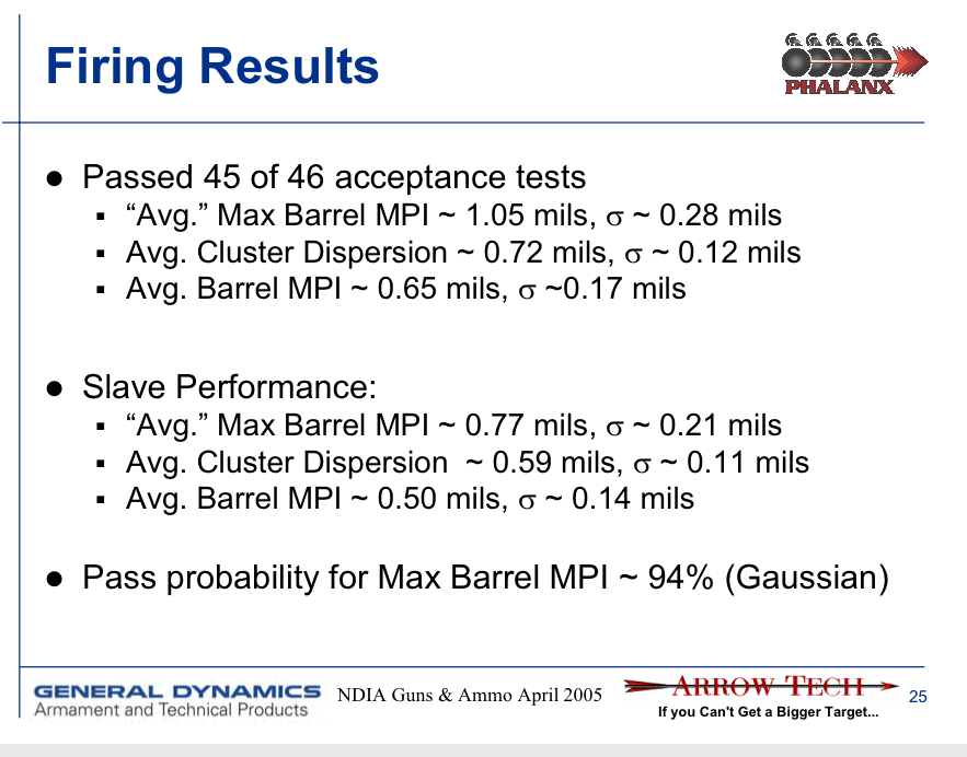
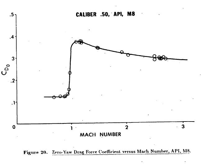
The drag on the bullets the Sabre uses are to high. The F-86 uses the bullets as defined in the lua files as. shells = {"M2_50_aero_AP","M20_50_aero_APIT"}, mixes = {{1,2,2,1,2,2}}, -- In the shell table the drag currently is defined as M20_50_aero_APIT.lua cx = { 0.5, 0.61, 0.8, 0.27, 2 }, M2_50_aero_AP.lua cx = { 0.5, 0.61, 0.8, 0.27, 2 } The variables are defined as. -- Drag (Сx) = { 0.5 , -- Cx_k0 Cd0 at low mach ( M << 1) 0.61 , -- Cx_k1 Peak Cd0 value 0.8 , -- Cx_k2 steepness of the drag curve before the transonic wave crisis 0.27, -- Cx_k3 Cd0 at high mach (M>>1) 2 , -- Cx_k4 steepness of the drag curve after the transonic wave crisis } Drag profiles for all the rounds are available from primary sources. Primarily, the US Ballistic Research Lab. The first two drag profiles are from the Ballistic Research Lab's 1990 range test. "The Aerodynamic Characteristics of .50 Ball, M33, API, M8, and APIT, M20 Ammunition. By Robert McCoy. https://apps.dtic.mil/dtic/tr/fulltext/u2/a219106.pdf Lets start with the API M8 Then The M20. Finally We have a drag profile for the M2 AP round. This chart is in older format Kd. However this can be converted to the standard notation for the Drag Coefficient Cd / Cx. The conversion is Cd = (8/Pi) * Kd The method is given in McCoy's work. The drag profile is from Report 620, Aerodynamic Data for Spinning Projectiles” H.P. Hitchcock Ballistic Research Laboratories, Aberdeen Maryland 1947. https://apps.dtic.mil/sti/pdfs/AD0800469.pdf From the chart, peak drag occurs at Mach 1.2 and the Kd is ~ .161 Converting using McCoy Cd = (8/Pi) * .161 Cd = .4099 At mach 2 the Kd is = .14, therefore the Cd = .35 The slope of drag curve at Mach > 1 is = .4 - .35 / .8 = .05 The drag at low Mach is ~.078 Kd = .1985 Cd The slope of the drag profile before area transonic appears flat. Therefore the drag for the rounds should look more like, M2_50_aero_AP.lua cx = { 0.198 0.4, 0.0, 0.4, .05 }

-
Chain gun: Effective engagement ranges?
Curly replied to Hummingbird's topic in Military and Aviation
This is from 1995, I dont know if the accuracy has been increased since then. https://apps.dtic.mil/sti/pdfs/ADA299307.pdf
-
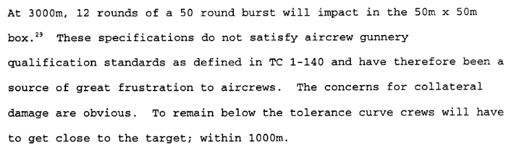
reported CIWS dispersion and addition of MK149 shell
Curly replied to nighthawk2174's topic in Weapon Bugs
https://ndiastorage.blob.core.usgovcloudapi.net/ndia/2005/garm/tuesday/siewart.pdf https://www.academia.edu/32755624/Phalanx_Block_1B_CIWS_Ready_For_The_Fleet_
-
The drag values for the 50 cal ammo look off. There seems to be two sets of drag values. One for the world war 2 assets. 50Browning_APIT_M20.lua cx = { 0.5, 0.61, 0.8, 0.17, 2 } 50Browning_API_M8.lua cx = { 0.5, 0.61, 0.8, 0.17, 2 }, 50Browning_AP_M2.lua cx = { 0.5, 0.61, 0.8, 0.17, 2 }, 50Browning_Ball_M2.lua cx = { 0.5, 0.61, 0.8, 0.17, 2 }, Where the values are -- Drag (Сx) = { 0.5 , -- Cx_k0 Cd0 at low mach ( M << 1) 0.61 , -- Cx_k1 Peak Cd0 value 0.8 , -- Cx_k2 steepness of the drag curve before the transonic wave crisis 0.17, -- Cx_k3 Cd0 at high mach (M>>1) 2.0 , -- Cx_k4 steepness of the drag curve after the transonic wave crisis } And, a second set of drag values for the 50 cal for the F-86 and possible the P-51 mustang. M20_50_aero_APIT.lua cx = { 0.5, 0.61, 0.8, 0.27, 2 }, M2_50_aero_AP.lua cx = { 0.5, 0.61, 0.8, 0.27, 2 } -- Drag (Сx) = { 0.5 , -- Cx_k0 Cd0 at low mach ( M << 1) 0.61 , -- Cx_k1 Peak Cd0 value 0.8 , -- Cx_k2 steepness of the drag curve before the transonic wave crisis 0.27, -- Cx_k3 Cd0 at high mach (M>>1) 2 , -- Cx_k4 steepness of the drag curve after the transonic wave crisis } First thing to note is that entries for the world war 2 assets have a peak drag value 40% lower than the older entries. M2_50_aero_AP.lua cx = { 0.5, 0.61, 0.8, 0.27, 2 } Vs 50Browning_AP_M2.lua cx = { 0.5, 0.61, 0.8, 0.17, 2 }, However both seem high compared to real world data on the rounds. Source: https://apps.dtic.mil/sti/pdfs/ADA289645.pdf And: Source: https://apps.dtic.mil/sti/pdfs/ADA219106.pdf Based on the charts the drag should possible look more like this Cx = {.12, .375, .0, .35, .0 } So a lower intial drag with a shallower rise, but a higher peak drag. With a much more gradual decrease in drag at high mach.
-
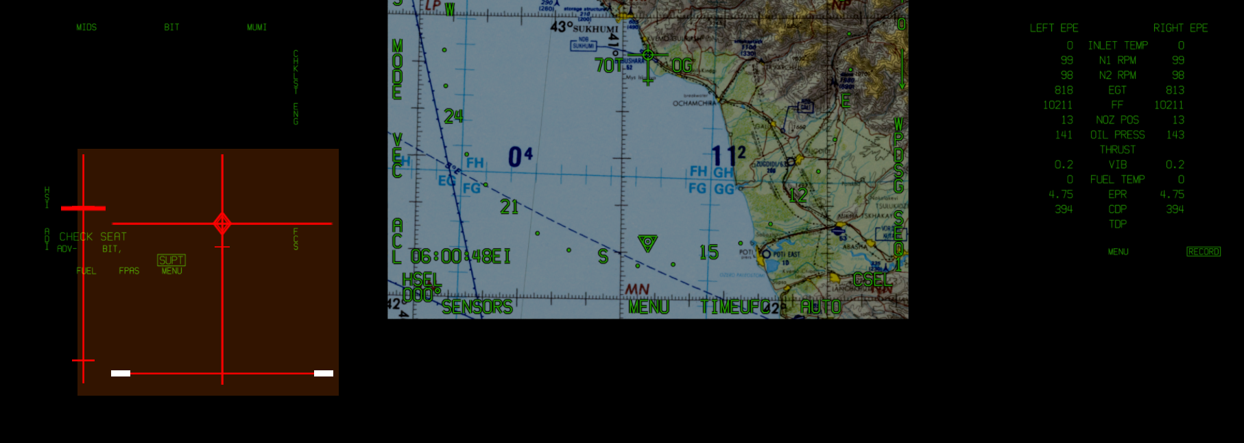
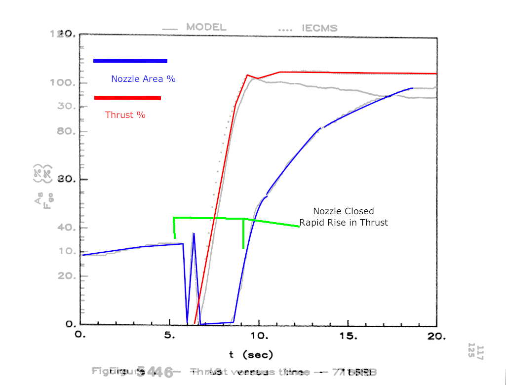
TLDR: two parameters of the engines, EGT, and nozzle area may be off, leading degraded transient performance. I think there may be 2 discrepancies with the F404 engines leading to marginal performance in the transient response of the engine. By which I mean the thrust output of the engine shortly after the throttle is moved. For now I will be discussing the response of the engine from Idle to Mil. The two issues are, 1, the EGT is too low and 2. The engine’s exit nozzle schedule may be off. First, the Exhaust Gas Temperature (EGT) on the engines looks low. The charts in the NFM-000, pages III-10-15, provide the operating EGT and RPM as function of temperature. The chart indicates, At full mil, with an inlet temp of zero celsius, the engine operates at 99% RPM with an EGT of between 830 c and 860 c. In game the EGT is ~ 815c, which is below the minimum operating condition. Low EGT is indicative of an engine that is under-performing and not putting out enough thrust. While the difference seems marginal. Low EGT can lead to a set of interconnected discrepancies. Which results in an underperforming engine. These interdependencies would exhibit themselves most strongly in the areas of transient response. IE The power output of the engine, while and shortly after the throttle is moved. Now on to the nozzle area issue. Which, maybe a case of the tail wagging the dog. In the F404, At full mill and above, the engine’s exit nozzle size (A8) is varied with temperature sensed aft of the low pressure turbine. (T5). Below Full mil the area is scheduled with the throttle position. When the throttle is moved to the full Mill position, the nozzles closes until the EGT limiter kicks on. https://www.sto.nato.int/publications/AGARD/AGARD-CP-448/AGARD-CP-448.pdf Page 64. https://asmedigitalcollection.asme.org/GT/proceedings-pdf/GT1990/79054/V002T02A035/2399309/v002t02a035-90-gt-357.pdf The result is a rapid rise in thrust. Below is engine data taken from a takeoff of CF-18 with 404-400’s. I’ve overlaid the nozzle position with time and the thrust with time charts. It shows the relationship between the thrust onset and the nozzle position. Note the rapid rise in thrust once the nozzle fully closes. Max thrust is reached ~ 3 seconds after the nozzle closes. The source is a Canadian paper on the development of computer model of the F404-400. https://curve.carleton.ca/c6dd200c-1bce-4711-9596-443f1cf85e70 In game, the only time I can get the nozzle position to 0 is when the throttle is 50% or lower. I know our Hornet has a different model engine, a 404-402. However, the 402 has higher thermal limits and therefore the nozzle position should stay closed even longer ~ 4 seconds when the throttle is moved to mil. If the nozzle position is too large during the transient, performance suffers. https://www.sto.nato.int/publications/AGARD/AGARD-CP-448/AGARD-CP-448.pdf Page 398. Since the resulting loss of performance tends to only show up in the transient response of the engine. It’s easy to miss the effect a misscheduled nozzle has on engine performance. NASA had the same problem with their dynamic engine model of the F404 https://www.nasa.gov/centers/dryden/pdf/88204main_H-1643.pdf Worse case scenario for the in game Hornet is that the combustor and or compressor isn’t operating properly and the nozzle is scheduled to far open. Or is the nozzle just too far open resulting in lower than optimum EGT’s? I suspect the latter, that the nozzle schedule is simply off. I can think of two reasons why this may have happened. First, there may have been a misinterpretation of the schedule. Most of the literature about the engine says, the nozzles are fully closed at “Intermediate Rated Power” IPR. Which seems like it would be 50% of the throttle lever range. However GE and NASA define IRP as full mill, 87° Power level angle. https://www.nasa.gov/centers/dryden/pdf/88068main_H-1375.pdf https://apps.dtic.mil/dtic/tr/fulltext/u2/a164562.pdf Since the nozzle area only seem to close to 0% at 50% throttle, it may be that it’s simply misscheduled, because the term intermediate rated power is confusing. The nozzle area may also be off because of how the game translates joystick position into throttle angle. This is related to where full mill is throttle range in game Vs IRL. In game full Mil is approximately 75% of the throttle position. In the real jet, Ground Idle, is 18°, Flight idle is 32°, full mil power is 87° and max power AB is 130° Power Lever Angle. So the throttle operates over 98° of PLA in flight and 112° of PLA at ground idle. At ground idle, if we want full mil the throttle lever should be moved 87° of throttle. This is ~ 77% (87/112) of the range of the real jet. In game full mil occurs at 75% throttle.So how does the game handle the scaling difference. It could be a source of mismatch, you may be taking off at below mil power. With the engine operating on a below optimal engine schedule. The same is also true while inflight. The throttle operates over 98° from 32° flight idle to 130° Max A/B, With full Mil power at 87°. Full mil in the real jet is at %88 of the throttle, while in game it’s at 75%. Depending on how the scaling is handled, with your joystick at 75% you may not actually be in AB yet. Which could make AB light times seem too long. Concluding, I think it would be a good idea to check the nozzle scheduling. If that’s correct, Then perhaps check how the joystick to throttle angle scaling is handled and see if there are any discrepancies. Then perhaps look at compressor and combstor engine performance. In order to find out if there is an issue with engine performance in transient response. enginerunup.trk
-
The technical term from delay between a change in the power lever angle and the engine thrust is called transient time. The delay between the engine response is often done purposely, as a way to prevent compressor stalls, or excessive temperatures. There is actually quite a bit of public data on the F404-400 and it’s engine control unit. Which regulates fuel flow and nozzle exhaust area by monitoring, various pressure, temperature and rpm speeds. This is from a NASA experimental fitting of fiber optic sensors to a Hornet’s F404 engine. So the sensor type isn’t representative of a production engine. However it provides a good overview of their placement. https://ntrs.nasa.gov/api/citations/19980219005/downloads/19980219005.pdf This from NASA bench test of the F404 and shows where the sensors are located internally. And another from a NASA paper on real time engine monitoring. https://www.nasa.gov/centers/dryden/pdf/88244main_H-1750.pdf An evaluation of F404 by the Aussies provides us with a glimpse of how the Engine Control Unit, ECU, on the 404 operates. https://apps.dtic.mil/dtic/tr/fulltext/u2/a164562.pdf Power level angle (PLA) break outs. Ground ilde 16 degrees, flight idle, 37 degrees, Intermediate power setting ( full mil), 87 degrees. Min AB, 90 degrees, Full AB 130. A8 Nozzle Area. TI inlet temperature TT5 low pressure turbine discharge temp (NL)N1 inlet Fan Rotor Speed rpm (NH)N2 Compressor rotor speed., High pressure compressor rotor speed PS0: Free stream static pressure (also noted as P0) PS3: Compressor discharge pressure. PS6: Afterburner inlet static pressure, absolute PS7: Exhaust nozzle inlet static pressure absolute PT5: Turbine discharge pressure absolute. Wp Fuel flow. That’s probably a lot of static to most people, but that chart is showing us what defines the operating limits of the F404. We can see the fan inlet RPM NL (N1) varies with power level angle below mil. However the ECU regulates N1 RPM based on T1 temps and pressures (PS1A) when the throttle is above a Mil, PLA> 87 degrees. Also evident is compressor surge protection. As the afterburner schedule is overridden when Compressor discharge pressures (PS3) are 425 psi and above. So if you dive in full after burn you won’t explode the engine. What’s probably most interesting about the chart is variation of nozzle area (A8) with power level angle below Mil. The implication is that the thrust response to the power level angle is not linear throughout the range of motion. The thrust response to power level angle varies depending on the position of the power level angle. “Loiter” and “Flat Cruise” power level angle settings will have different variations in ratio of thrust per degree of power level angle. NASA recognized this when they were developing their Dynamic Engine Model for The F/A-18 HARV simulation. https://www.nasa.gov/centers/dryden/pdf/88204main_H-1643.pdf They came to the conclusion that they could get a pretty good simulation of the engine response by interpolating thrust from a look table. And applying a rate limiter and low pass filter to the power level angle position to mimic the nonlinearity and transient response of the engine. There however was flaw with the approach. The model was missing 20% of thrust for a brief period around 8 seconds. Since there seems to be a fixed delay in the DCS Hornet, it seems like we have version of NASA HARV engine model in DCS. Where there is a fixed delay in thrust. If the delay is made variable with static pressure the model would be realistic and avoid the problem NASA had with their fixed schedule. https://apps.dtic.mil/dtic/tr/fulltext/u2/a466188.pdf I know you're probably saying, Curly we have F404-GE-402. What the hell are you talking about again? Back to the engine at hand then.Lets look at how the F404-GE402 got it’s increased power. It’s on the order of a 20% increase in Ps, specific excess power. https://asmedigitalcollection.asme.org/GT/proceedings-pdf/GT1990/79054/V002T02A006/2399359/v002t02a006-90-gt-149.pdf “On the Leading Edge F404 Turbofan Engine” S.F. Powel, F404 Advanced Programs Manager GE. 1990. “The increased thrust of the -402 model will be achieved by increasing fan speed up to 2%, improving afterburner efficiency and raising turbine inlet temperature by +100°F (+5K) at intermediate rated power, increasing to +175°F (+97°K) at maximum power.” The increased performance of -402 could only be realized with a more aggressive ECU schedule. To create more power the ECU of the 404-402, would allow for an increase in the pressure in the combustion chamber. This could only be accomplished by the increased inlet temps by 100F. Which also would drive RPM higher. That and the increased afterburner efficiency are why the 402 has a lower specify fuel flow than the base line model despite generating more thrust. These changes also brought some other interesting performance changes to the engine and aircraft. Flight testing of the 404-GE-402 in the Hornet shows faster after burn light times than the base line model. Flight testing of the engine shows afterburner light times from Mil to MAX A/B below a second. From: F/A-18A/B/C/D F404-GE-400/402 ENGINE SLOTTED SPRAYBAR INLET FLAMEHOLDER FOLLOW-ON FLIGHT TEST EVALUATION https://apps.dtic.mil/dtic/tr/fulltext/u2/a407860.pdf This disagrees with the afterburn light time and charts in the NFM 000. The one in the NFM 000, with light times of >6 seconds, look like they may be from the base F404 engine not the 404-GE-402 the DCS hornet models.
- 55 replies
-
- 14
-

-

-
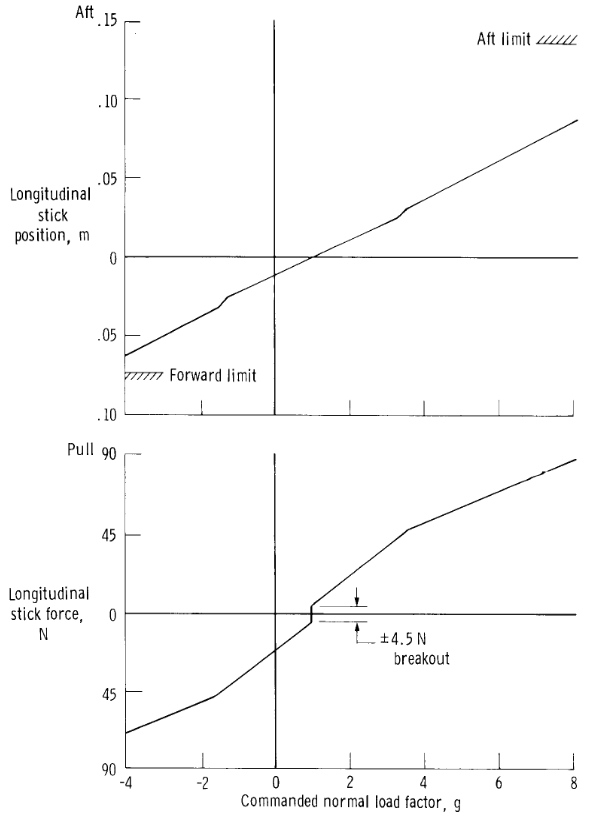
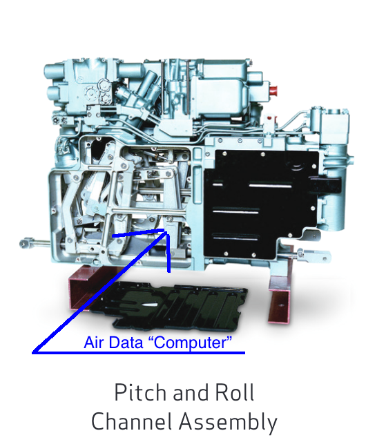
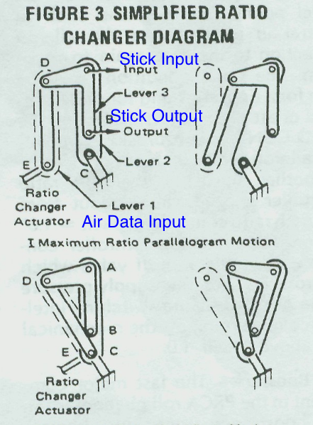
The F-18's FCS was more like an advancement of the F-15's. The F-15's FCS is based around a hydro mechanical system and a control augmentation system. It has a moving stick with a force sensor. The stick is physically connected to the control surfaces through a series of mechanical boxes designed to provide specific handling qualities. The F-15 and F-18 were designed to have similar handling qualities. That is a consistent amount of G per stick force. Just to clarify, the amount of G per stick force is different for each aircraft. Hornet Stick Force per G. F-15 Stick Force Per G The force sensor on the F-15's stick was essentially a means of error correcting the mech flight controls to deliver the stick force per G schedule. While the mech system is geared to deliver this G schedule, sometimes it needs help or is overaggressive. Lets say the pilot pulls the stick back .025 meters, this take ~45 newtons of force. This should result ~ 3g. However there are transients in the system. This where the stick sensor comes into play. It detects the amount of force the pilot is exerting on stick. If the G command is different from the G sensed; The CAS system then drive the stabilizers to achieve the commanded G schedule. This is all done through a series of analog systems. The air data scheduling is done through a series of mechanical monsters. Instead of using a computer and an algorithm to compute the air data schedule like the F-18 does. The F-15 uses this parallelogram ratio changer to alter the amount of control surface deflection commanded based on air speed and altitude. Even the F-15's CAS system is essentially an analog fly by wire system. All the signal processing being done by Op amps, resistors, ect. Which isn't a problem because the system works as intended for the most part. The F-16's first FCS was also analog. It used a system of resistors and amps, ect like the f-15's CAS. The Hornet took the concept of the F-15's FCS and digitized it. This would get rid of all the mechanical monsters and updating the FCS would be as easy as loading new software. The initial design used a moving stick with the force sensor attached, just like the F-15's. However the hydro mech input system was only to be used as backup. It was essentially deactivated unless the aircraft was operating in a degraded mode. The force sensor alone was now the input to the FCS. However there were teething problems. Using the force sensor with the stick never really worked well with the Hornet. In the early FCS they had to digitally filter out some of the stick dynamics. Since the stick moved and sensed force, the interplay of dynamics got complicated. Think of a sudden acceleration. This throws you back in the seat, causing you to accidentally apply more force to the stick, causing the craft to pitch up. The engineers recognized these type of effects and built in a lot of digital signal filters and transfer functions. The result was complicated and computationally expensive. Which led to a laggy system prone to pilot induced oscillations. This is discussed in Flight qualities development report I linked above. Since the early system was so problematic, they just abandoned the force sensor concept. Though the did leave it on stick, empty and non-functioning. That is where the linage from the F-15 still remains. re: the curves in the gradients: Note that the stick force per G is linear. The non linear stick gradients in FCS, are part of the way the FCS tries to linearize the response of the aircraft. This is not same reason that we put curves on our sticks in the sim. We do this be cause we want finer contronl of the aircraft. Which is reasonable given the small throw of a desktop joystick. Flight testing... That's the limiting factor in updates. There is never enough time or money do everything. When OFP 10.5.1 was being tested. What was believed to be a very simple change to the AOA probe failure logic, resulted in a serious amount of problems. Handling qualities in approach were dangerously degraded and a lot of time and money was spent trying to fix it. After all was said and done the only fix was to rem out the dual aoa failure logic. Read about it https://apps.dtic.mil/dtic/tr/fulltext/u2/a307768.pdf The roll controls are ubiquitous in the FCS. To realize an automatic roll control. You would either have to change gain schedule to make it more aggressive or implement an integral / derivative feedback system. Either of which would require a complete validation of the entire envelope. There is nothing easy or cheap about those changes. The legacy only got the 10.7 OFP because they piggy backed on the Super.
-
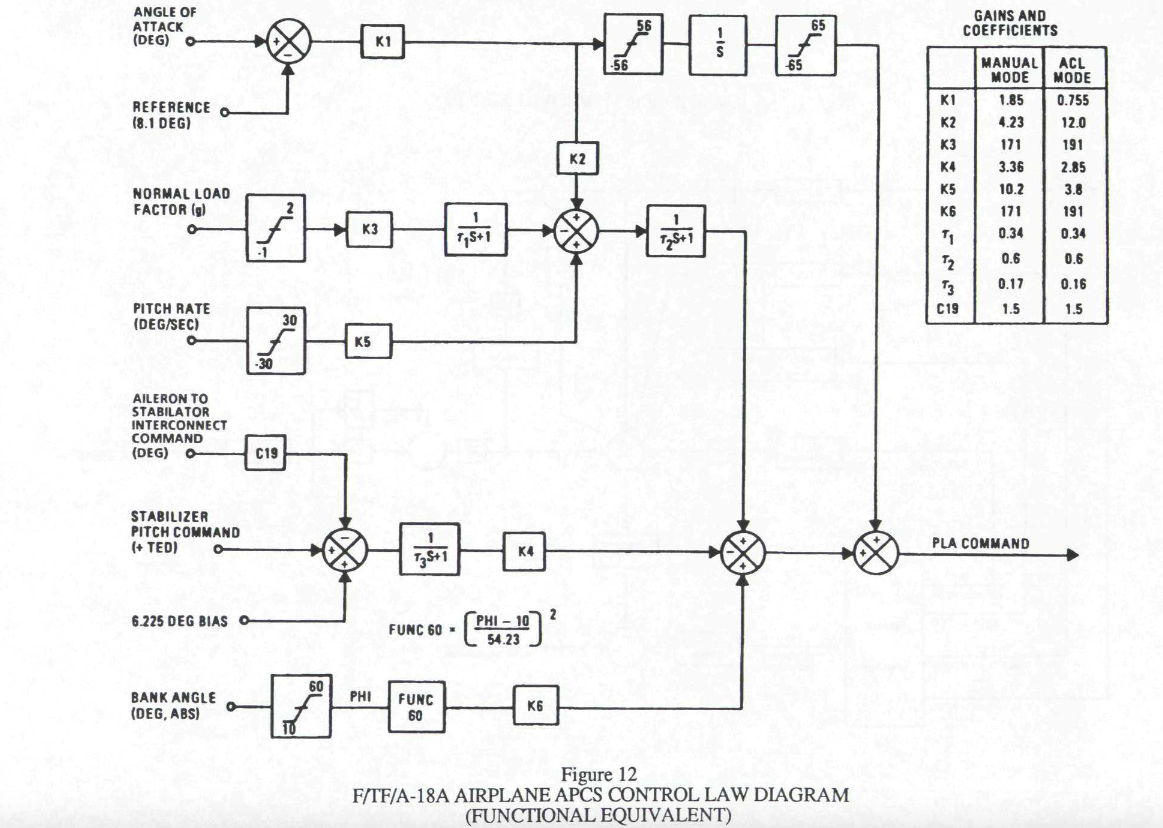
The auto throttle system on the hornet has two separate operating modes. When the flaps are up, the system operates as Velocity Control System (VCS). This is what the good book, NFM-000 pages 1-2-8 to 10, call the ATC cruse mode. In cruse mode, Air data (air speed) is feedback and causes the throttle to move. Thus controling the air speed. If the flaps are in half, and few other criteria are meet, pressing the auto throttle button engages the Approach Power Compensator. Which the good book, NFM-000, calls The ATC Approach Mode. When the auto throttle is in APC mode, it's designed to maintain an angle of attack of 8.1 degrees and modulates the throttles to do so. Seems easy on paper, but the dynamics are orders of magnitude more complicated than the Cruse Mode. In APC mode, system Feedbacks include angle of attack, G, pitch rate, stabilizer command, and bank angle. Each input has unique impact on the change in angle of attack and thus command of the throttle. So each input needs a unique set of gains. This is a block diagram of the system from an old AGARD report. This diagram tells us, a negative amount of G, positive pitch rate, a stabilizer command trailing edge up (stick aft), or an angle of attack of more than 8.1 will cause the throttles to advance. Each input is gained depending on they individually effect the angle of attack. The gains are based on the unique characteristics of the Hornet and the engine performance. In short the system is complicated, dynamic and dependent on the basic flight and engine models. If those models we’re in flux, every time you changed a flight / engine model parameter you would have to go back and figure out your APC gains again. That’s probably why the APC and the Automatic Carrier Landing system will be one of the last systems implemented. Who knows, maybe it’s all ready built with the AGARD gains, but increased thrust of the EPE engines make behave poorly. Link to the AGRAD: https://www.sto.nato.int/publications/AGARD/Forms/AllItems.aspx?RootFolder=%2Fpublications%2FAGARD%2FAGARD%2DCP%2D509&FolderCTID=0x0120D5200078F9E87043356C409A0D30823AFA16F60B00B8BCE98BB37EB24A8258823D6B11F157&View=%7B7E9C814C-056A-4D31-8392-7C6752B2AF2B%7D That AGARD report is a pretty interesting read too. There's a lot of details about the Hornet buried in there. How the hud computes the flight path marker and even the old (pre 10.5.1) Trim to AOA command schedule. There’s some cool experiments described too. Ski ramp takeoff with a Hornet anyone? Here’s a low fi version of the same doc. https://apps.dtic.mil/dtic/tr/fulltext/u2/a244869.pdf
-
The 570-100 PRINCIPLES OF OPERATION INTEGRATED FLIGHT CONTROLS NAVY MODEL F/A-18A/B/C/D 161353 AND UP
-
I felt the need to describe the entire flight contronl system in detail because, they way you talked about it made it seem like that the force sensor was the singular input. It is not. Nor is it the largest input. The CAS and therefor the stick force transducer, can command at most +-10 degrees of stab. The example was meant to be an illustrative overview of the FCS operation not a literal account of the air data schedule. Re "The FCS isn’t responding to inputs until the pilot overcomes the breakout force and displaces the stick. As is illustrated in this in this document about the F-15’s FCS from NASA." What is the pitch force deadband network in the CAS and why do you think it exists? If the stick is centered in the 1 G trim position, how much force do you have to apply to overcome the dead band filter and cause the stick transducers to apply voltage to the CAS? What is the mechanical breakout force required to actuate the hydro mech system, how far does the stick move after that force is applied? The desired result of both systems F-15/F-18 is to provide a constant G per stick force. The sticks are geared, for lack of a better term, to require a specific amount of force to move them a specific distance. In the F-15 the stick physically actuates the stab servos to attempt deliver that response. Moving the stick an inch aft takes ~10 lbs of force and is designed to result in a load factor of ~4g, given the right conditions. When the stick force transducers outputs 10 lbs of force, if the G is less than 4, Then previously described Feedback loop begins. So the command load factor is dependent on the stick position the same way it's dependent on the stick force, since they are derivatives of each other. The Hornet operates the same way. It just has a digital position sensor commanding the stab servo and is only physically linked to servo in degrade modes. Moving either stick a fixed distance / force commands a predetermined load factor. Force and distance are coupled.
-
The Stick force sensor is integrated in the F-15 FCS as a way to detect command error. That is the difference between the command G (stick position) and the actual G. The hydro mech system of the F-15 is geared to deliver a consistent G per stick displacement based on the air data (dynamic and static pressure). There however areas of transient response where the hydro mech system alone will not deliver the command G. This where the CAS system comes in play. The stick force sensor in a way double checks what the pilot is asking for and moves the stabs via the CAS servos to meet the G command schedule. However the CAS system can only move the stabs +- 10 degrees. So what happens when the pilot deflects the stick full aft at 250 knots? The hydro mech system moves the stabs a fixed amount based on the air data. Let just say the basic gearing of the hydro mech system can only deliver 7 g in these conditions. Well, then the CAS reads the force inputs from the stick sensor and goes, oh the pilot is commanding 8g, here's another 10 degrees of stab. The CAS then further bias the hydo mech system through the CAS interconnect servo. Causing the hydro mech system to move the stabs further than basic air data limits would normally allow. The CAS then goes, well there is still full force on the stick sensor, so we're still commanding 8g, but now were at 7.5 G. So now I'm reducing that +10 stab I gave to 5, and I'm going to bias the hydro mech system a little bit more. This loop continues biasing the hydro mech system until the CAS servos are centered and no longer command further stab movement. The CAS provides immediate error correction and biases the basic hydro-mech system to meet the designed G schedule. The the stick sensor and load factor are the error signal. But yes you can actually fly the F-15 FBW with the hydro mech system disconnected, using the force sensor alone. However your are limited to +-10 degrees of Stab movement. So the entire flight envelope is not available. The hydro mech system also incorporates a means to correct for command errors based on stick position too. It's done through the Pitch Trim Compensator. Which is what the CAS is biasing as it makes corrections. Stick inputs are fed into a high-class, accelerometer-controlled servo loop known as the load factor error sensor (LOFES), a part of the PTC. This stick input establishes the neutral or zero point it works around. For example, let us assume that a pilot, or the trim actuator, is holding the stick in a position commanding a load factor of one g. Any subsequent deviation from that setting will be sensed by the PTC accelerometer which will valve hydraulic pressure to the pitch trim compensator piston, repositioning the piston and commanding the required amount of collective stabilator to keep the aircraft at one g. This series trimming capability is true for disturbances created by flap, speedbrake, and landing gear extensions. Acceleration and deceleration are also compensated for, producing an essentially neutral speed stable airframe. Since the trim change we've described is "series," no stick movement is noted. With the CAS off, the aircraft will still try and hold 1 g with the stick in neutral. It will also maintain The stick force to G schedule when the stick is displaced via the air data scheduling of the stabs. However there are areas in flight envelope where it will not be able to do so. The system requires both stick movement and force sensing to deliver the entire flight envelope. It is not like the F-16's where the force sensor is the sole input to the FCS. The Hornet has the force sensor in the base because the original FCS was supposed to use only the force as FCS input. There were a lot of problems with this implementation though. You can read about them here. http://aviationarchives.blogspot.com/2015/01/f-18-flying-qualities-development-report.html So the force sensor was replaced with position sensors. In many ways the F-15's FCS is the fore-bearer of the Hornet's. Except the Hornet digitized the functions of hydro mech system. Many of which where simply analog computers. The mechanical ratio changers on the F-15, that geared stabliator deflection based on air data. We're replaced with a computer. The CAS hydro-mech interconnect, CAS Servos, and pitch trim trim controller and pitch trim compensator replaced by a feed forward integrator.
-
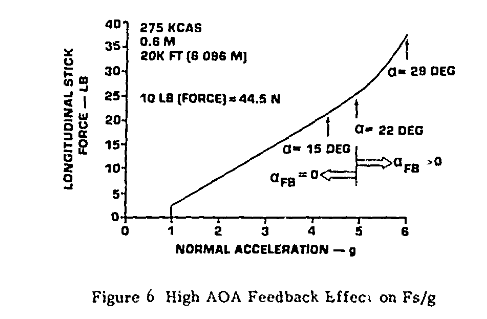
In short the FCS won’t accept input unless it’s greater than the breakout force. However, there are a few thing to unpackage and explain here. First, the stick in Hornet isn’t force sensing. A series of LVDTs sense the movement of the stick and communicate this to FCS computer in the terms of voltage. So the input to the FCS is based on the position of the stick. Not the force exerted on the stick. There is also a series of springs which provide resistance to the stick's movement. This is called the feel system. When you use the trim buttons, The feel system moves the stick. The FCS and feel system are setup in a way so that the displacement of the stick results in a consistent force irregardless of it’s trim position. Meaning, no matter the trim position of the stick, the same amount of force is required to displace the stick a given distance. EG if the stick is trimmed full forward, moving the stick 3 inches aft requires the same amount of force as needed to move the stick 3 inches aft, if no trim was applied. Here is a visualization of that from the F-15’s FCS. The Breakout force is a deadband that moves with the trim position. It’s meant to replicate the slack that exists in many conventional flight controls and eliminate any accidental inputs to the FCS. For a lack of better term the stick is stuck in the trim position until you overcome the breakout force. The FCS isn’t responding to inputs until the pilot overcomes the breakout force and displaces the stick. As is illustrated in this in this document about the F-15’s FCS from NASA. So the best way to make fine adjustments is with the trim system, Trim inputs bias the FCS and move the stick. Zero trim input means zero bias in the FCS. In the case of the Hornet, zero trim commands 1 g in most conditions. Pressing the trim switch aft will causes the FCS to seek a G greater than one by pitching the aircraft nose up. If you wanted you could trim the aircraft to hold a 2 g turn. And moving the stick out of the breakout position would command the FCS to seek the bias + the input. So if we trimmed the F-15 to 2 g’s and applied 45 Newtons of force, The FCS will seek close to 6 g. As the input to the CAS is the trim bias (2) + stick command ( ~4g) . However, there are pilots who don’t like the feel of breakout and will trim the aircraft nose down and hold the stick aft beyond the breakout force. Thus any slight force applied to stick moves it and results in an immediate input to the FCS. This way you can make many fine inputs. This technique coupled when coupled with a beefier center spring allows groups to put on impressive displays.
-
You don't understand the content of those papers. They are not referring to a physical simulator with a joystick. So there isn't a "different sensor for stick travel". They're making a computer program to replicate the FCS and the aerodynamics. The inputs are data typed into program, then iterated and output as set of variables, Matrices in the case of DTIC paper. Again, no joystick. The NASA simulation was designed to produce trim shots based on stick position, thrust, ect. For the results to be valid they had to use the actual FCS and it’s governing functions. Which is why they went to such great lengths to publish those. I was wrong about one thing y = x (7.0 + 2|x|) is non linear. It’s Just the graph in the DTIC (MDC) is more exaggerated. That is literally the stick function gradient as defined by the manufacturer. **Stick Gradient Function** y = x (7.0 + .02|x|) For half Stick Aft, 2.5 inches 18.75 = 2.5 (7.0 + .2|2.5|) Y/X = 7.5 = Slope of Gradient For Full Stick Aft. (5 inches) 40 = 5 (7.0 + .2|5|) Y/X = 8 The slope increases as inputs increases. There is a reason why this done that you don't understand.
-
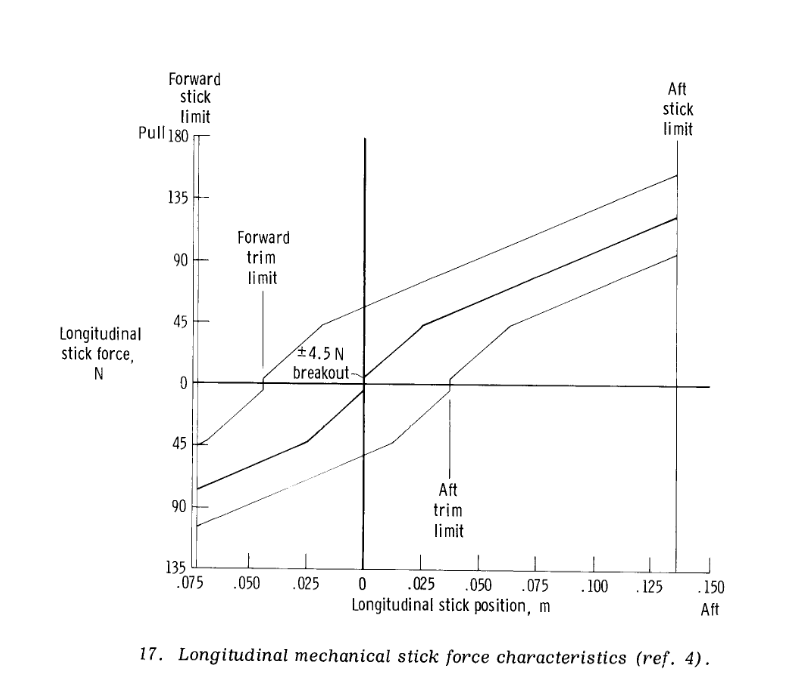
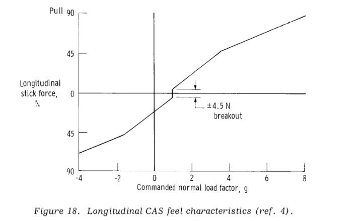
TLDR: If you’re looking to model your stick forces via a cam profile. Probably best to model the F-15’s and skip the breakout force dead zone. See Pages 40-43. https://www.nasa.gov/centers/dryden/...ain_H-1073.pdf If your stick doesn’t have an adjustable force profile, just leave it be It’s probably fine. Yes stick forces are lighter in the roll, that pretty typical for an FCS. If you’re looking to shape the cam profile here are a couple things to keep in mind. This gets complicated because your trying to model something that may or may not be modeled. Unless the breakout forces are modeled. It will be hard to replicate the effects of the breakout forces (dead-band) without a force feedback stick. The break out forces in the real jet function as a movable neutral zone. In DCS, setting the dead zone just applies area of zero input around center of stick. Once your stick is outside of that dead zone, the input jumps to the next variable up. EG if you set a dead zone of 25. Once Your stick position hits 26 the input to the jet is 26. So you can lose areas of fine command with the dead zone. 2. In the real jet the stick moves further aft than forward, 2.5 inches to 5 inches. This also changes depending on the flap setting. 2.5 inches forward and 3.5 aft in half and full. I don’t know how they handle this in game, possibly scaling the forward inputs down. More forward joystick commands less in game stick movement than aft joystick? IE moving your joystick forward 1 inch moves the hornet’s stick forward a half inch. Vs moving your joystick aft 1 inch then moves the Hornets stick Aft 1 inch. You end up with more definition in the forward throws this way BTW. 3. The force gradient might not be perfectly linear on the real Hornet and moves with the trim position. This is better illustrated with some force gradients charts from the F-15. Again nice and open sources NASA stuff. https://www.nasa.gov/centers/dryden/...ain_H-1073.pdf Fig 17 on page 40 illustrates this. It takes more force per centimeter to move stick within 50 centimeters of deadzone than it does outside this zone. And the G command per unit of force as seen in Fig 18 follow suit, Stiffer around the center. What’s interesting on NASA doc I posted earlier is Function 20. https://ntrs.nasa.gov/citations/19920024293 Which shows volts (fcs input) to stick displacement. We can see it’s linear. However, I think this is an oversight by the author of the NASA doc. In the older work I also posted https://apps.dtic.mil/sti/pdfs/ADA176333.pdf. One page 68 the author notes he linearized the longitudinal, lateral, rudder and RSRI gradients. For Function 20 he converts the non-linear equation to y = x (7.0 + .02|x|). Looking at image of Gradient on page 87 of the DTIC doc, we can see the stick gradient is very non-linear. 20 years later, NASA uses the linearized gradient, y = x (7.0 + .02|x|) for function 20 in the FCS. Which we know from the older docs is an approximation. However in the Feed forward integrator section of the FCS they use the non linear gradient, y = x (0.06+.0156|x|), for function 115, which is called Nonlinear Stick Gradient. The NASA model also incorporates some of the non linear dynamics left out the older DTIC model (Func 116, 117). Without spending more time than I care to, I can’t tell if they are adding non-linearity to stick gradient there. Which is my hunch because ,The older Function 20 and Function 115 both look like a non linear stick gradient with a small breakout force. Either way, You’re probably best just trying to model those F-15 force to CM displacements. That would get you close enough without force feedback. Which I don’t think is implemented on the Hornet yet.
-
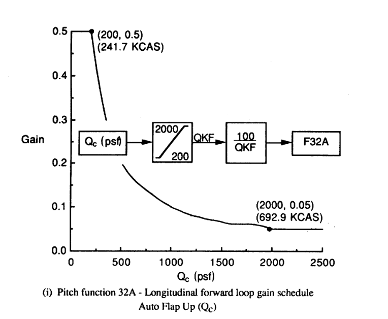
There are few really good open source documents on the Hornet’s FCS. The best and most recent is from NASA. It describes the system as follows https://ntrs.nasa.gov/archive/nasa/c...9920024293.pdf “The pitch CAS uses a pilot commanded longitudinal stick position input as a command to the CAS. The forward path gain is air data scheduled (Function 32A) to yield a uniform initial pitch acceleration response for sharp inputs. The CAS feedback parameters are a blend of air data scheduled pitch rate (Functions 40 and 68, normal acceleration, and angle of attack. Pitch rate and normal acceleration feedbacks give improved pitch dynamic characteristics and load factor control in the mid to high dynamic pressure portion of the flight envelope. Air combat maneuvering characteristics and increased stick-force-per-g cues in the low to mid dynamic pressure flight regime are provided by the air data scheduled pitch rate feedback. Angle-of-attack feedback provides additional increased stick force cues for low speed high angle-of-attack air combat maneuvering. Roll rate multiplied by yaw rate is fed to the longitudinal control system (Function 107) to reduce the effects of inertial coupling. “ So yes it does have a similar function as the pitch ratio changer on the F-15. Many of the same people worked on both systems, F-15, F/A-18, at MDC. (Abercrombie, Harschburger) http://aviationarchives.blogspot.com...8-growing.html https://ocw.mit.edu/courses/aeronaut...controls_1.pdf https://ocw.mit.edu/courses/aeronaut...controls_2.pdf Since the NASA doc provides the air data schedules, you can see how the gains change based on air data. Where Pitch rate, G and angle of attack feedbacks become more dominate. Thus effecting the stick forces per G. In this older report you can see how the system iterates via the program and diagrams, How the sensor inputs effect stabilator, position when Air data is fixed and the stick is held aft. However this particular version of the system does use an older gain schedule and force inputs for stick command. All of which was later changed. So while it gives a nice overview of how system responds it’s not accurate to the current system. https://apps.dtic.mil/sti/pdfs/ADA140143.pdf An even older version of the FCS is available here. You can track and see how the gains change as the FCS is updated. Some of which are deleted. https://apps.dtic.mil/sti/pdfs/ADA176333.pdf Which is why you have to aware of the dates of when these papers are published and what version of the FCS they are referring to. As handling qualities changed with FCS updates. http://aviationarchives.blogspot.com...8-growing.html https://apps.dtic.mil/dtic/tr/fulltext/u2/p002709.pdf https://ocw.mit.edu/courses/aeronaut..._mit_brief.pdf However if your looking for a baseline stick force gradient one is available. https://apps.dtic.mil/dtic/tr/fulltext/u2/a256522.pdf Break out forces of +-3.0 lbs and a stick force gradient of 7.4 lbs and inch. With stick moving 5 inch aft and 3 inches forward in the Up and away. Gripes your quotes if from the super hornet NATOPS. There are some differences in the FCS between both craft. The one that stands out in your quote is the use of rudder toe in UA flight. This was never added to the legacy hornet.
-
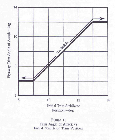
The Take off trim system on the Hornet is unique. The trim system bias the feed forward integrator to capture a specific AOA, once the system detects weight off wheels. Pressing the takeoff trim button sets the bias to 4 degrees of Angle of Attack. The carrier takeoff trim settings of 16 to 19 degrees, sets the system to capture 12 degrees of AOA. The system is designed to pitch the aircraft at a rate of 12 degrees per second, a form of auto rotation, once the weight is off the wheels. With increased gross weight, additional trim is required to get the aircraft to rotate. The system is limited to 12 degree AOA capture. Trim above the recommend settings for a given weight, will just increase the rate of rotation once weight is off wheels. This could cause AOA overshoots and pitch rates that are uncomfortable. Setting the trim below the recommended setting will cause excessive sink rates off the bow and slow AOA capture. Full flaps carrier takeoff with half flap trim setting present a different problem. Increased pitching moments, resulting in rapid over rotation and AOA overshoot. Half flap was chosen as the recommend setting because the benefit of full flaps catapult take off ( lower catapult end speeds) did not weigh concerns about sink off bow or auto rotation issues. Just as an FYI the field trim setting will always require you to pull back to rotate the aircraft. The trim capture is mentioned in the NATOPS sections 14.1 emergency carrier takeoff.
-
Max AOA at CL max at 15k ft is 34 degrees. https://ntrs.nasa.gov/citations/19950007836 The G limiter is what is preventing AOA greater than 34 degrees. Corner is where CL max meets the airframe limitation. In this case the 7.5 g limiter. CL max for the airframe is 1.8 at an AOA of 40. To achieve that AOA you need to be below the G limiter. https://www.nasa.gov/centers/dryden/pdf/88489main_H-2149.pdf While There is no AOA limiter on the airframe. Pitch rate, NZ and AOA feedbacks will dampen pitch rates. It looks to that what you’re bumping into either the NZ limiter or aggressive integrator at action above 30 degrees of alpha. https://apps.dtic.mil/sti/pdfs/ADA140143.pdf
-
Will EXP3 mode of air to ground radar be optimized and improved?
Curly replied to kaoqumba's topic in DCS: F/A-18C
I'm not trying to answer for Lex, but even with the RUG 2 upgrades, I wouldn't expect the world. The displays in the cockpit are 480 by 480 pixels. Even with the increased capabilities of the SAR, you'll basically looking blobs. 1 meter resolution is still very grainy and given the display size the images wont resolve clearly. Even down to .3 meter resolution it's is difficult to distinguish targets. The ultra high rez stuff that looks like photos, is likely 10 centimeter and below. This is a set of targets at a .3 meter / 1 foot resolution at 128 by 128 pixels Can You tell the bulldozer from the tank? Even that resolution is way beyond what the hornet is capable of. Since were talking about a 1 meter resolution over .5 km on a 480 x 480 display a T-72 will resolve to a 9 by 3 pixel image. The target strip comes from the MSTARS database, which is publicly available and often used in validation of auto target recognition software. https://www.sdms.afrl.af.mil/index.php?collection=mstar&page=targets
-
Will EXP3 mode of air to ground radar be optimized and improved?
Curly replied to kaoqumba's topic in DCS: F/A-18C
From the 2001 training plan. https://www.globalsecurity.org/military/library/policy/navy/ntsp/f-18-a_2001.pdf Page 19, In FY98, Lot XX series F/A-18C/D Aircraft were delivered,integrating the Phase II AN/APG-73 RUG, ATARS, Joint Direct Attack Munitions, Joint Stand Off Weapon, Initially The APG-76 was limited to a .8nm / 1.5 km patch with a resolution of 3 meters / 10 feet. Slightly less than resolution than the APG-70. Around the same time it recvived similar upgrades to 70 to achieve those resolutions.IE Upgardes to the IMU and more signal processing power. https://www.researchgate.net/publication/3633660_Adaptation_of_ANAPG-76_multimode_radar_to_the_smuggling_interdiction_mission -
Will EXP3 mode of air to ground radar be optimized and improved?
Curly replied to kaoqumba's topic in DCS: F/A-18C
The APG 70 is capable of a 4 foot / 1 meter resolution map over an area of .33 nmi. This made it possible to distinguish a SCUD TEL from a MAN truck and a ZIL command van 150 feet apart. https://apps.dtic.mil/dtic/tr/fulltext/u2/a347534.pdf 8 foot / 2.5 meter resolution is available up to 20 nmi https://apps.dtic.mil/dtic/tr/fulltext/u2/a319223.pdf The Phase 2 RUG was delivered on all lot 20 aircraft. I think we're limited to a 16.4 foot / 5 meter resolution over a 1.2 nmi range in DCS. If you keep the target designated in EXP 2 the resolution will increase until the gimbal limit. However I’ve yet to see anything below 1 nm. Before the RUG 2 updates the 73 was limited by the airframe vibrations and movement and couldn’t calculate it’s position accurately enough to be capable of higher rez SAR maps. The upgrade included a custom imu, a new waveform generator and power supply. After this upgrade it was capable of ranges of the APG-70 and the U-2 ASARS. If you look at the previous posted images from the CIP paper. That’s about a 1 meter resolution image. It's just over a larger area. Probably a ATARS spot map processed to a single image. So you could reasonable expect that level of detail just over a smaller area in a RUG 2 APG 70. -
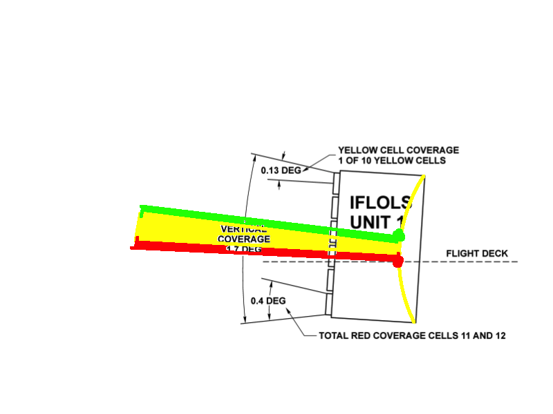
The IFLOLS is about 500 feet from the ramp. So Aft of the ramp the light appears larger than the size of lenses on the IFLOLS. At the ramp the meatball would appear about the size of lens on the IFLOLS. In real life it would move in same analog fashion as the gauge. The ball would appear between the lenses on the IFLOLS as you moved up down the glide path. When you are on glideslope at the ramp you are looking at light from the top and bottom of the 6’th and 7’th lens at the same time. Let’s do a little thought experiment to illustrate the point. Let’s say the 6 and 7’th light on the IFOLS are different colors, Red and Green. What color is the on ball glideslope beam at the ramp? It’s yellow. Because Red + Green = Yellow.