Fox One
-
Posts
447 -
Joined
-
Last visited
-
Days Won
2
Content Type
Profiles
Forums
Events
Everything posted by Fox One
-
I have even started a thread about it : http://forums.eagle.ru/showthread.php?t=127712 For me personally, the geometrical accuracy of something I always see in front of me when I fly is pretty damn important. But my impression is the vast majority of people really don’t care much about such details. That’s why I have very, very low hopes it will be corrected.
-

Question regarding different types of guns
Fox One replied to WinterH's topic in DCS: Fw 190 D-9 Dora
Fw 190 D-9 used the same KG 13B stick grip as earlier Fw 190 versions. There are 3 weapon buttons on the stick : A, B1, B2. A (trigger): fires the synchronized weapons (MG 131, MG 151) B1 (on top of the stick): fires the outer wings guns (not available on D-9, so this button does nothing) B2 (left side of the stick): bomb drop. This button is also used to fire WGr 21 or R4M rockets. -
External tanks related – I believe when dropping tanks, the upper part of the pylon (called a ferry beam) should remain attached to the plane, while the tank TOGETHER with the rest of the pylon should drop.

-
http://forums.eagle.ru/showthread.php?t=127712
-
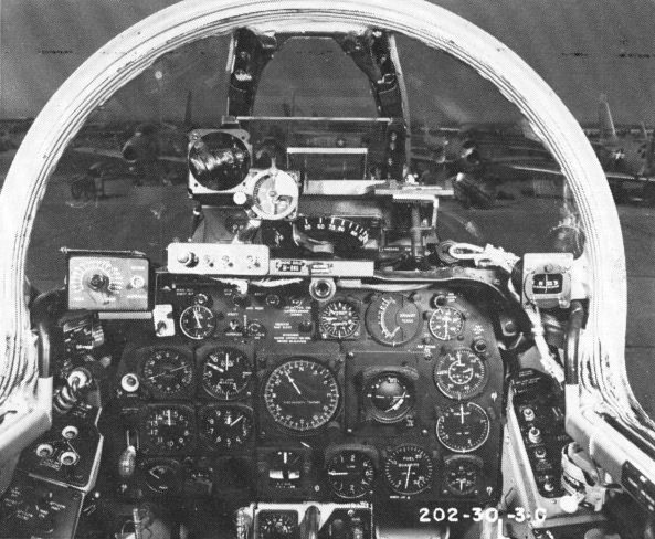
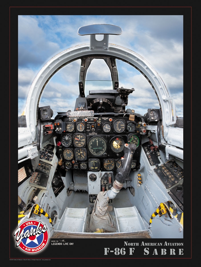
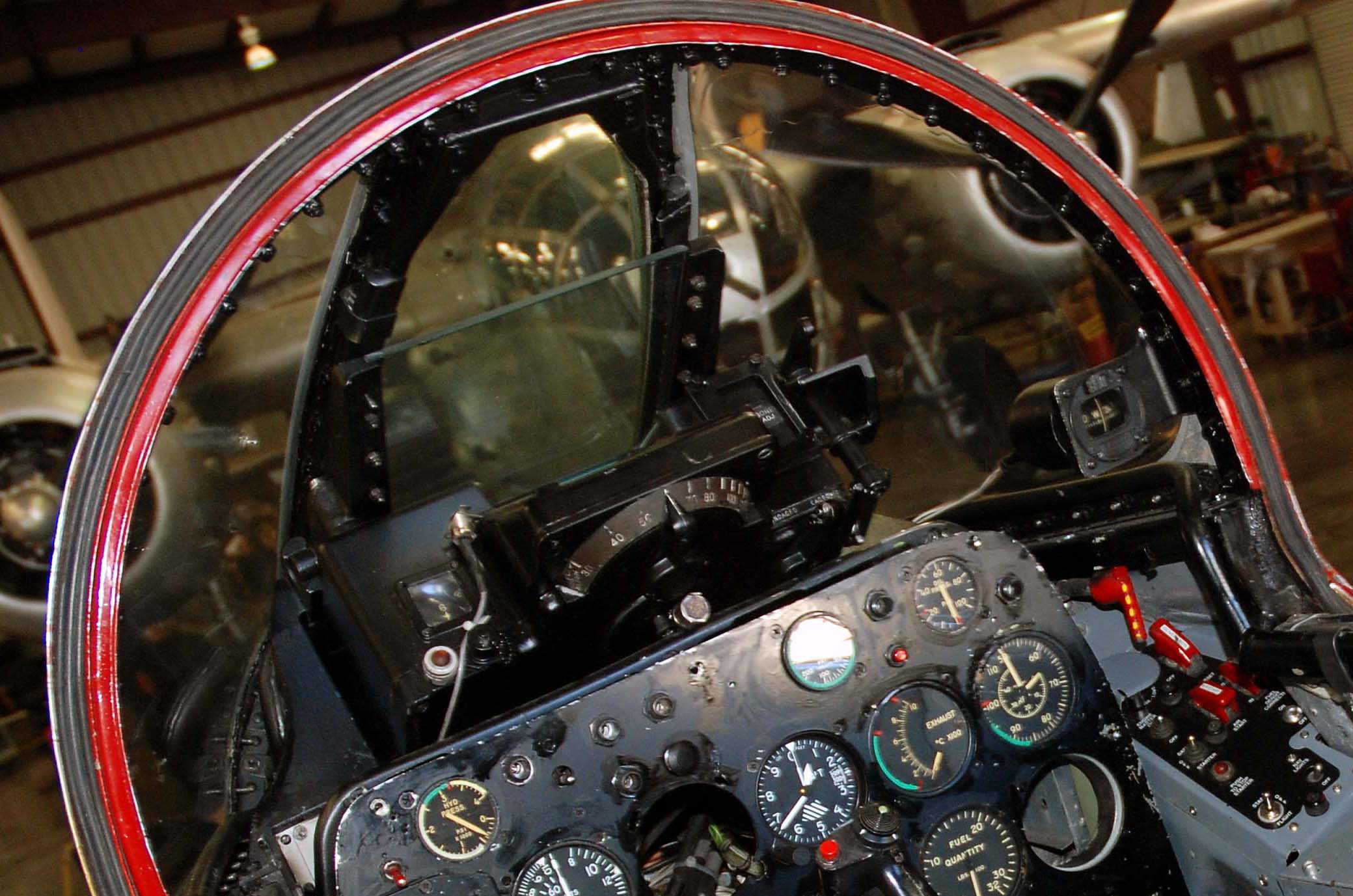
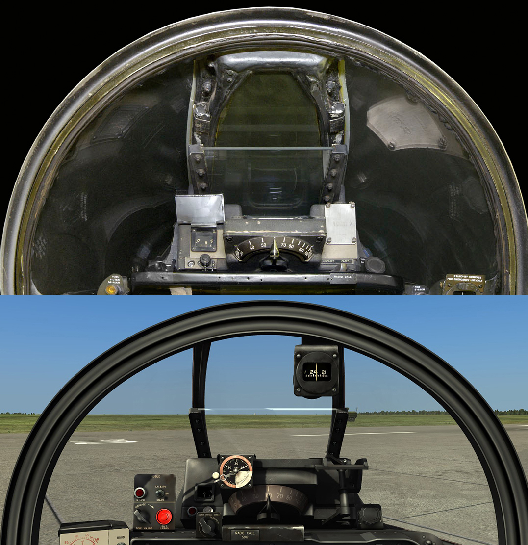
Cockpit instruments are not what this is about. It doesn’t matter. All pictures are of E and F models and, as expected, the windshield in all of them is identical. In day fighter variants of the Korean War (A, E, F) the windshield was changed only once, from the early V-shaped one. And it is obvious in none of the pictures is a V-shaped windshield. So there is no need to find the correct pictures, they are already correct. The best way to prove I’m wrong would be to post some pictures that actually look like DCS model ;)
-
Other pictures of the flat windshield with its details more visible.
-
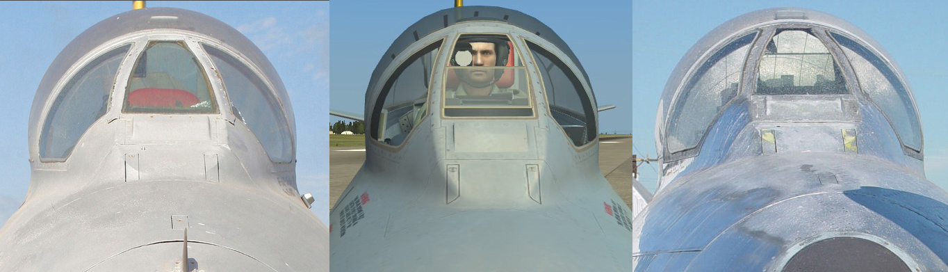
Please see picture 1 below. The problem with the flat windshield on DCS model is that it is too wide in the upper part. Also see how in the pictures of the real thing on the upper part of the flat windshield it is visible how the framing inside the cockpit actually gets even more narrow. In picture 2, on the upper part of the flat windshield the point where the framing inside the cockpit gets narrower than on the outside is clearly visible, giving the characteristic shape. The uppermost part of the flat windshield is like 3 times more narrow than DCS model! Also see that is not only a matter of the shape of the flat windshield, its metal framing is also considerably wider than on DCS model. The combined effect of all the errors – the windshield in DCS as seen from the cockpit practically doesn’t resemble the real thing.
-
Cockpit textures IDENTICAL with MiG-15 cockpit 3d model you can see here http://psy06.deviantart.com/gallery/?offset=0 are already in a folder inside DCS install ;)
-
From DCS manual, page 29: “The tanks are daisy-chained and fed into one another.” No, they don’t fed into one another. Front and rear fuselage tanks fed into the engine’s main pump. Page 31: “When drop tanks are used, the Fuel Selector Switch should be set to “Hinten”. The Fuel Contents Gauge will continue to display full for as long as the drop tanks continue to feed the rear and in turn the forward tanks. Once the drop tanks are emptied, the fuel quantity in the rear tank begins to decrease.” Unfortunately things are not that simple. First, the rear tank doesn’t feed the forward tank. It can’t. As I said above, both fuselage tanks can only feed the engine pump. Actually there is no piping whatsoever between the front and rear fuselage tanks. This is true for any Fw 190 ever built, from A-1 to D-9, as the technical manuals clearly show. Second, the fuel quantity in the rear tank won’t show full, then begin to decrease after the drop tank is empty. That is not how it works. The pipe that feeds from the drop tank to the rear tank actually connects to a special limiting valve, mounted in the rear tank. If the plane carries a drop tank, that limiting valve will only open when the rear tank content drops below 240 liters. So, if a drop tanks is used, fuel consumption order would be like that: At first, no fuel is consumed from the drop tank, because the limiting valve is closed. So in the beginning fuel will be consumed from the rear tank, until its level drops to 240 liters. Only then, the limiting valve will open and allow fuel from the drop tank to feed in to the rear tank. When the drop tank is empty, the fuel level in the rear tank will drop below 240 – this is the indication that the drop tank is empty. Since the fuel system from D-9 is practically identical with A-8, I suggest ED to check Fw 190 A documentation from http://www.luftfahrt-archiv-hafner.de/ In the docs there is a manual, Bedienungsvorschrift-Fl with pilot instructions for all Fw 190 A version, from A-1 to A-8. How the fuel selector and pumps switches should be used is clearly described. The entire part about fuel system usage by the pilot covers several pages, so what’s in DCS manual is only scratching the surface. Very short summary about fuel system use from the instructions – when a drop tanks is attached, in the beginning the forward fuselage tank fuel pump shouldn’t be switched on. Fuel from the forward tank will still feed the engine pump (on condition the fuel selector is on “Auf”, that is how it should be), but it will feed only due to gravity, so at a much slower rate than the rear tank, with its pump on. Necessary for correct center of gravity position. When the drop tank is empty, switch its pump off, and switch on the forward tank fuel pump. Next, when the white warning light for rear tank 10 liters is on, close the rear tank with the fuel selector, rear tank pump off, switch indicator to forward tank. But what if there is no drop tank, the forward tank pump is on, so most likely the forward tank 90-100 liter level light will go on first? Close the forward tank with the fuel selector and empty the rear tank, then close the rear tank, rear pump off. As a general rule, once a fuel tank is empty, it must be closed with the fuel selector, to avoid air from the tank reaching the engine’s main pump.
-
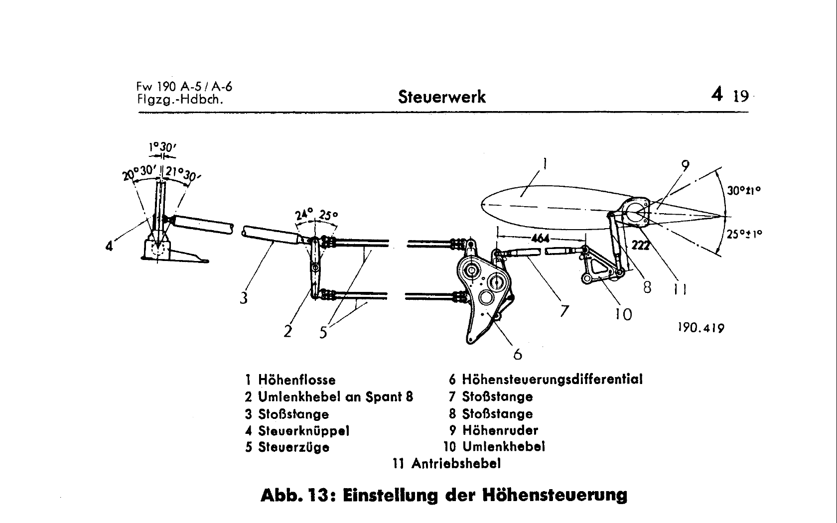
Yes, Fw 190 A-5/A-6 Flugzeug-Handbuch, Teil 4: Steuerwerk, but you can also find this particular document online, for free.
-
Bucic, could it be this what you are looking for? http://forums.eagle.ru/showpost.php?p=2007057&postcount=7
-
Both controls appear in a Fw 190 D-9 technical manual (Lehrmittel) from January 1945. If the control "MW-50 to Fuel Handle of water-methanol tank" really looks like that, I haven't yet seen any evidence, and probably nobody really knows. "Radio self-destruction button" - in reality that is IFF (FuG 25a) destruction button, not radio. I think it is safe to say that on the real plane they did not put for this a switch similar with the Netzausschalter (electric-kill switch)... Nobody would put a big, accessible switch like that that could be pressed inadvertently and destroy the plane's IFF. http://forums.eagle.ru/showpost.php?p=2008632&postcount=12 Here I pointed that the switch was most likely under a metal guard, and I also indicated the switch type according to Fw 190 A-8 tech documentation, I am reasonably sure they didn't changed it on D-9, after all is the same IFF type. Search the switch type on http://www.deutscheluftwaffe.de/ , actually it is a simple toggle switch.
-
See post #41
-
No, I uploaded just 2 pics. But about what part of my post are you talking?
-
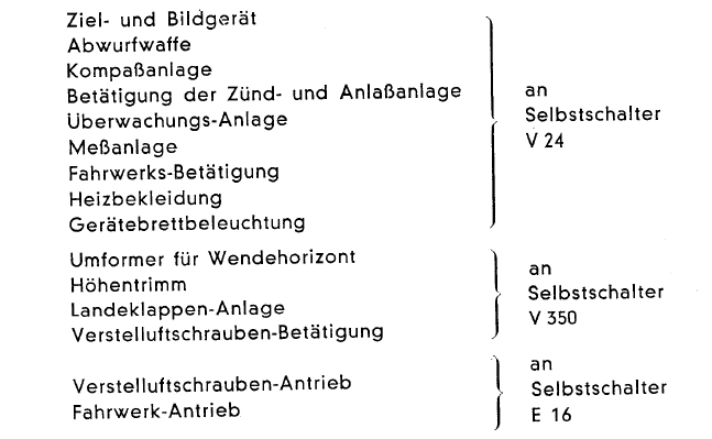
In image 1 below, on the left is the schematic for late-series Fw 190 A-8/A-9 and on the right is the schematic for D-9. What’s written in red are my notes. The late-series A-8, in comparison with early-series were equipped with a simplified version of the electrical system. Such planes had an important change in the cockpit - the aft group of switches under cover was deleted. Fw 190 D-9 is similar. In planes without the aft group of switches under cover they managed to substantially reduce the number of switches by wiring some switches to power several consumers. In image 2 (that’s for A-8/A-9 version) you can see how on the new, simplified version of the electrical system switches V24, V350 and E16 now powered several consumers, transducers, etc. In image 1 compare the schematic on the left for late-series A-8 and A-9 with the schematic on the right for D-9. The differences are: - on D-9 Verstelluftschraube-Betätigung and Verstelluftschraube-Antrieb are missing. Those are for propeller control circuits and for propeller’s electro-hydraulic drive motor itself. On D-9 the propeller pitch control has no electrical parts, it is hydro-mechanical controlled by MBG. On Fw 190 A it is electrically-controlled, automatically or manually. On D-9 is only automatic, and there is no pitch indicator or direct, manual pitch control available. - the P80 Flügel außen is missing, as there are no outer-wing guns on D-9. Notice that diagrams in image 1 are actually for R11 subvariant. This is fitted with autopilot and electrically heated windshield. So to adapt the right diagram for D-9 to DCS version you must remove K1 Kurssteuerung (autopilot), Heizscheiben innen (centre windshield heating) and Heizscheiben außen (side windshield heating) and add EZ 42. Notice how the centre windshield heating is switched on by D1 Staurohr switch (Pitot heating). According to info from an A-8 technical manual, the switches for late-series A-8 and A-9 (without autopilot and heated windshield) would be placed in this order, from front to rear: P80 V350 E16 D1 F211 F136 V24 A4 A6 (the switches under cover) C1 E14 E13 E85 E96 (external lights and pumps switches, located close to the starting handle) A D-9 would have exactly the same switches, except for P80. Guns switches – on the lower side of the D-9 diagram, the “Scußwaffe” box with MG151 and MG131, the two switches connected with a line must be the big “master arm switch” on the SZKK that switches on the synchronized guns. On the right of this, the two switches inside a little box – I don’t know where exactly are they in the cockpit and why they represented them inside that box. Also the screenshots from the manual – the labels are written on the switch panel’s covers. This is correct for earlier Fw 190 A versions. On D-9 there is a little place to insert the labels, left of the cover, visible well in pictures. On the panel cover there was sometimes hand-written only switches ID, like F136, V24, A4, etc
-
Browsing the manual, I was very surprised to see 2 groups of switches under covers on the cockpit's right hand side. On D-9 the rear group of switches was deleted, and there is actually some proof for that. My question to ED's developers would be: what documents do you have that show on D-9 there are 2 groups of switches under covers? I would be very curious to see it. Also I was surprised by several switches there. For example, the Außenbord switch. The last Fw 190 version to have this switch was A-5, it was deleted on all newer versions.
-
About Fw 190 D-9 with EZ 42: http://forums.eagle.ru/showpost.php?p=1818980&postcount=422
-
9. We need better oxygen system info: tank capacity, which order the tanks were used in, approx. oxygen supply at different altitudes. On deutscheluftwaffe.de in documents section at "Dräger" check "Atemgeräte Höhenflugregeln". This manual, D. (Luft) 1205 is precisely the document the Fw 190 A manual say should be checked when preparing the oxygen system for flight. The Fw 190 D-9 oxygen system is identical with the one from A version, only on D-9 the oxygen bottles are mounted in the fuselage further back. In the manual there are stated oxygen reserve duration at various altitudes.
-
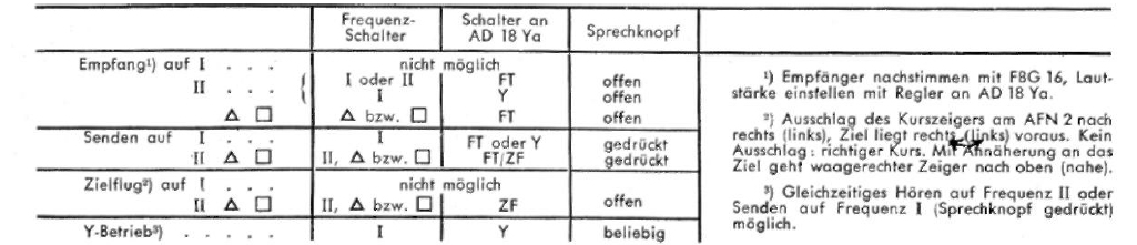
11. The Frequency dial – what do the frequencies actually do? The I position is for Y-Führungsfrequenz, or Management frequency. The II position is for Gruppenbefehlsfrequenz, or Group Order frequency. The ∆ position is for Nah-Flugsicherungsfrequenz, or the Air Traffic Control frequency. The □ position is for Reichsjägerfrequenz, or Reich Fighter Defense Frequency. That we're clear on. What they were used for however, we need more info on that. 12. The frequency dial and the AD 18 switch – what in the world does it affect? What's E-Messbetrieb? What's Zielflug-Anzeige? How did they actually work? What were the cockpit procedures? And why does the FuG-16 Handbuch only list interactions with AD 18 for Frequenzschalter in positions I and II, and nothing about ∆and □? In addition to csThor’s great description, I would add that in FuG 16 manual available at deutscheluftwaffe.de the procedures with I – II - ∆ - □ selector and the FT FT – Y ZF switch on AD 18Ya are clearly described (see pic). If you study carefully this manual and the one from csThor’s link, you will probably get all your questions unanswered.
-
In Fw 190 A-7 bis A-9 , Teil 9D "Bordfunkanlage" manual, the switch appears in both the diagram with components location in the plane, and also in the electrical wiring diagram. It is clearly stated the radio is FuG 16ZY (as expected). In the components location in the plane diagram, it is located in cockpit in the place described by luthier1 in his question.
-
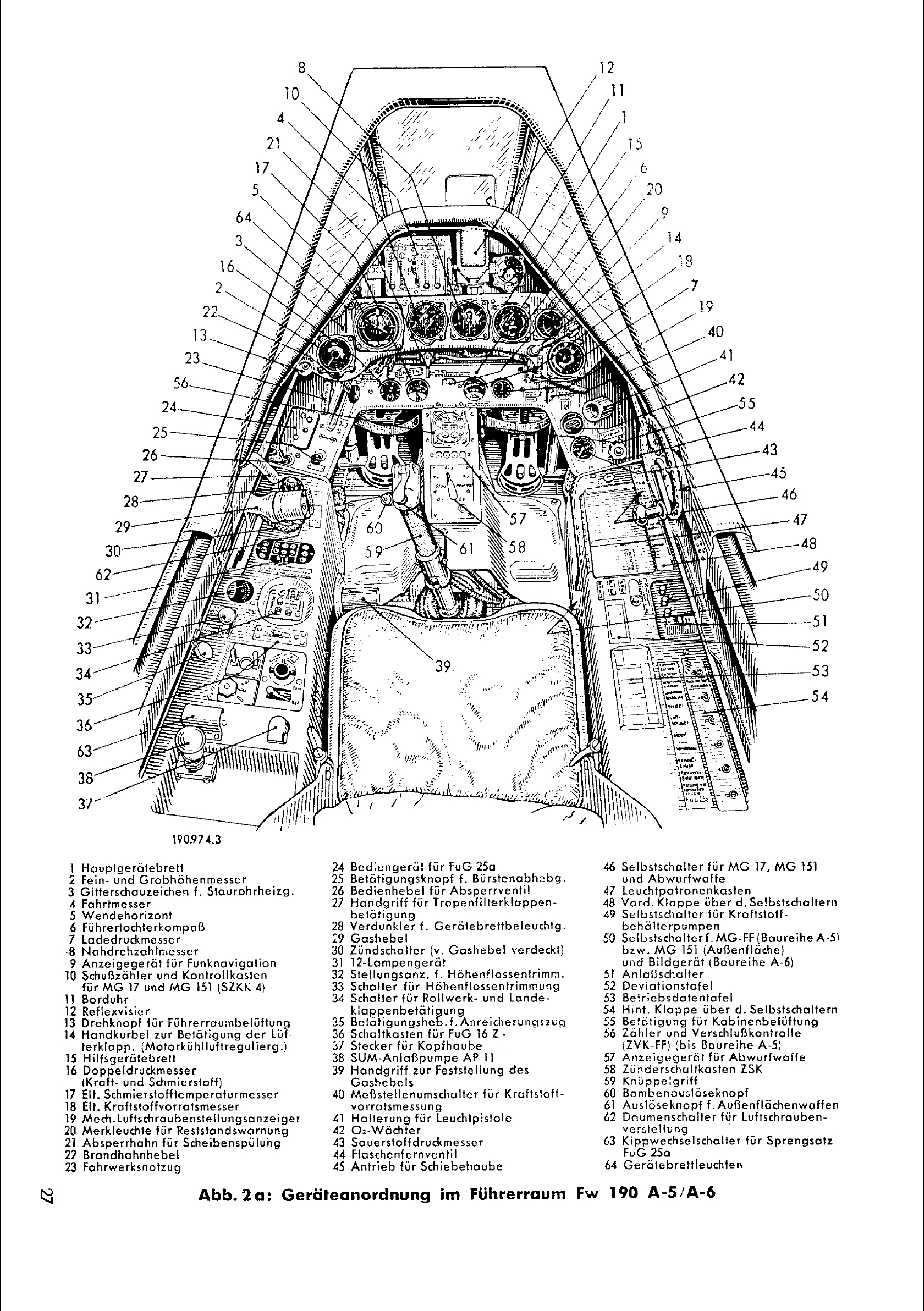
10. Some references have the left console with only one FuG 16 ZY frequency dial, while others have a second one next to it. The first one we’re clear on, but the second one – the FuG 16 ZY Handbuch does not seem to mention it, but it's right there in the aircraft Ersatzteilliste. We have no idea what the switch does. The I – II - ∆ - □ selector (F114) is the one closer to the pilot. The other, similarly looking switch is the Zielflug Fern-Nah (F116) switch. The aircraft W. Nr. 601088 I described in post #7 doesn’t have this switch. 14. What did the Flugzeugvernichter button look like? A cockpit diagram from the Lehrmittel appears to show it as an actual cockpit control on the right console. Small correction, the Lehrmittel show the control to be on the rear part of the left console. The FuG 25a destruction switch was mounted under a small metal guard. See pic below, even if it shows the cockpit for A-5/A-6, check #63. For FuG 25a, the switch type was Fl 32346-1, switch ID code F210.
-
4. How does the Notzug system interact with the MW-50 system? I suppose by “Notzug system” you mean the “Notzug für MBG” (Notzug für Bediengetriebe) handle in the cockpit. I’m not sure that’s actually a “system”, it’s just a handle connected through a cable with the MBG. I don’t think it has anything to do with MW 50, it’s just an emergency control to switch the MBG to some sort of default state, to be used in case of emergency when MBG malfunctions. It was probably intended only as a means for the plane to return to base, most likely full engine performance was no longer available. One thing is certain – D-9 planes without MW 50 also have this control. In the Lehrmittel manual for D-9 at engine start section they say the handle should be pulled when starting at temps below 0 deg C, then pushed back. In Ta-152H pilot manual (Jumo 213E engine) they say the engine will start better with handle pulled anyway. 6. We could use more info on the pull-out Kuhlerklappen handle. When was it used? What effect did the flaps have? Was it in any way connected with the Bediengerät? See pic below. The only cockpit control for radiator cooling flaps was a small wheel mounted below the main instrument dashboard. I don’t remember in which book I read that there was a marking on the wheel and another marking on the mounting plate. Aligning the two markings, would mean that 100 deg C was set, the cooling flaps control mechanism would adjust the flaps as needed, trying to maintain coolant temperature at 100. The pilot could turn the wheel left or right, in this way overriding the position of the flaps that was maintained automatically. Could manually completely open or close the flaps, if needed. AFAIK, the cooling flaps actuator wasn’t connected in any way with the MBG. The wheel in the cockpit was connected through a cable with the actuator/regulator device. The actuator was mounted above the engine and was controlled thermostatically, it didn’t involved any electric circuitry or mechanical/hydraulic input from MBG. All the actuator/regulator needed to work was temperature feedback, obtained through 2 pipes with hot coolant. Operation was simple – after engine start, the Lehrmittel manual says the flaps should be manually fully opened when coolant temp reached 70 deg C. Next, after takeoff the pilot most likely put it on the “100” position and leave it like that for the entire flight. Exception would probably be a long, maximum performance steep climp, where one would want to manually fully open the flaps with anticipation. After landing and engine shut down, manually fully close the flaps. 9. We need better oxygen system info: tank capacity, which order the tanks were used in, approx. oxygen supply at different altitudes. As Kodoss already said, the oxygen bottles were not used in any particular order, the bottles were connected through pipes with each other, see drawing in Lehrmittel manual. The normal filling pressure was 150 atm.
-
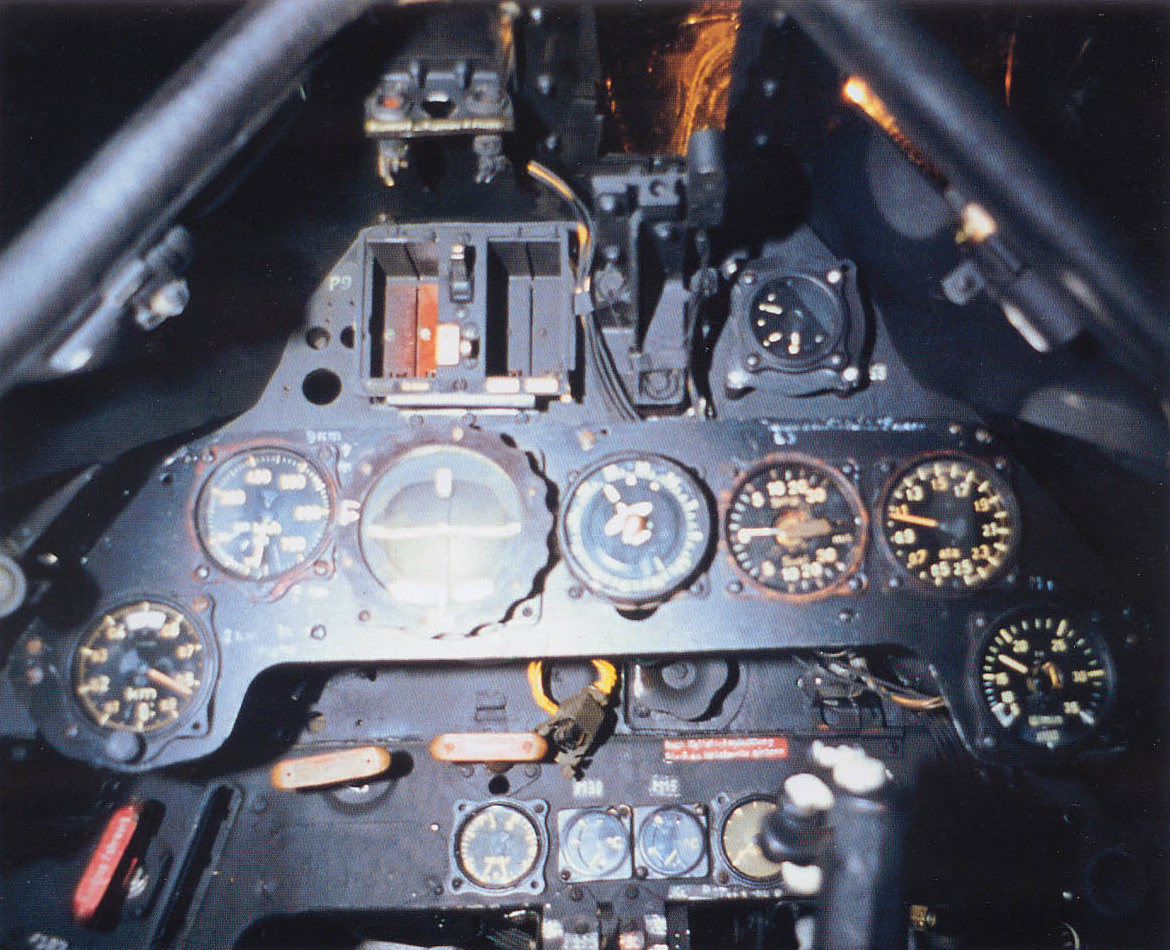
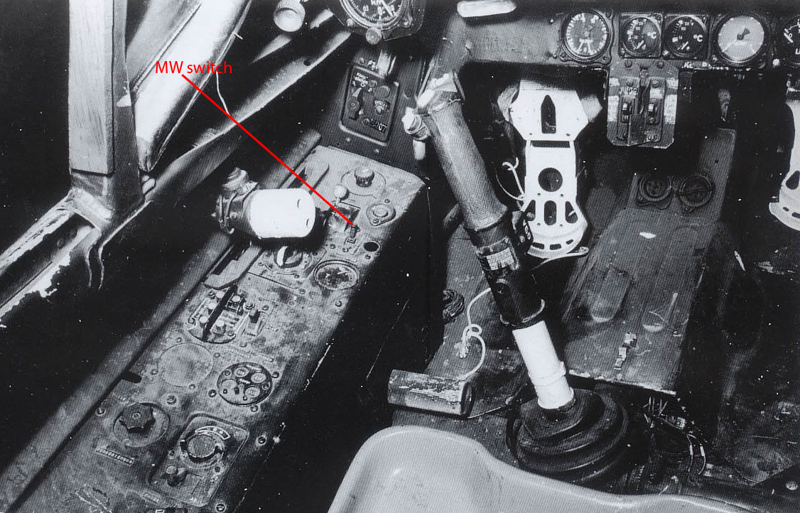
1. Is there any info on the technical specs of the boosted controls? By looking at the blueprints we can easily see the simple mechanism, but we need numbers. Is there anything like a graph or a text that says that for x degrees of control deflection you get y degrees of surface movement? What boosted controls? I’m not sure I understand your question. See pic 1 below – is that what you’re asking? The diagram is for A-5/6, but I don’t think the angles were changed on later versions, including D-9. 3. We cannot find good info on MW-50 Controls. Where is the On-Off switch? What does it look like (assuming Fl 32350). What about the MW-B4-Selector? See pic 2 below. I believe the dark circle next to it is the “MW switched on” indicator light. About the switch type, I looked at deutscheluftwaffe.de for Fl 32350 pictures – probably that’s the type. The MW-B4-Selector – in Jerry Crandall’s Fw 190 D book, vol 1 there are several cockpit pictures of W. Nr. 601088, displayed today in National Museum of the USAF, here are 4 pics of the cockpit as it looks today http://www.nationalmuseum.af.mil/factsheets/factsheet.asp?id=507 This particular plane was fitted with MW 50. What’s interesting about the pics in Crandall’s book, they were taken BEFORE restoration, so IMO they can be trusted to show how the real thing looked back then. In the pictures are visible the left side cockpit panel and part of the instrument panel. The differences between how the cockpit looks today and back then are: - the color today is obviously too dark - the landing gear position indicator and the I – II - ∆ - □ frequency selector are one in other’s place. The incorrect placement probably happened when the plane was put together in lack of technical documentation. The placement as seen in the unrestored pictures is also identical with Fw 190 A-8 and F-8 cockpit pictures, and conforms with drawings from technical manuals for Fw 190 A variants with FuG 16 - the trim indicator today is placed upside-down. The scale of the indicator shouldn’t be towards the pilot, but towards the wing. Pilot sitting should see the letter T on the indicator upside-down. Confirmed also by cockpit pictures of other Fw 190 variants. - the device identification letter/number codes handwritten next to various items in the cockpit are no more - the label describing landing gear lowering procedure ”Ausfahren des Fahrwerks……..” today is missing In the pictures of the unrestored cockpit there is no MW-B4-Selector visible in the location described in Lehrmittel. Also, there is no MW tank content emergency jettisoning (Schnellablaß) in the location described in Lehrmittel. My theory: they gave up installing Schnellablaß, and the MW-B4-Selector (or another form of selection control with the same function) was fitted somewhere in the airframe, not accessible in flight. The configuration of the auxiliary 115 liter tank was anyway decided before flight if it was to be filled with B4 fuel or MW liquid, the switch actually had no use to the pilot in flight. Or maybe to simplify the system, the MW-B4-Selector was removed completely, and before flight the plane’s mechanic, depending on what was desired, manually attached to the auxiliary 115 ltr. tank the pipe for the MW installation or, if it was to be filled with B4 fuel, the pipe connecting it to the rear fuselage tank. 5. Is there the Auto-Hand Luftschraube switch with the corresponding rocker switch on the throttle, as on the earlier variants? Of course not. The Auto-Hand switch on the left panel and the rocker switch on the throttle are missing on D-9. There is no manual electro-hydraulic pitch control like in Fw 190 A; on the D-9 the propeller's RPM governor can only be controlled automatically by the MBG; notice that, because there’s no manual control also there is no propeller pitch indicator. 7. Is there a good quality hydraulic system diagram anywhere? What hydraulic system? This plane doesn’t have any hydraulics. In the next days I will try to answer more of your questions.
-
That is correct, principially it worked like the gunsight in the Mustang. But what I was asking is, particularly for Me 262 equipped with EZ 42, where was the physical control for inputting range placed in the cockpit. In Mustang and Fw 190 D-9 with EZ 42 range was inputted by twisting throttle grip. But due to specific throttle design in Me 262, I don't think the control was also on the throttle.
-
Does anybody know, in Me 262's case, where from was range inputed in EZ 42 gunsight?