Fox One
-
Posts
447 -
Joined
-
Last visited
-
Days Won
2
Content Type
Profiles
Forums
Events
Everything posted by Fox One
-
^^^ The switch is not for turning on/off both SAU and SDU. Notice the label says СВЯЗЬ САУ-СДУ. СВЯЗЬ means connection, communication. It is for emergency disconnecting autopilot from flight control system if the autopilot starts going crazy.
-
Regarding inverted departure, it is interesting that the real aircraft is restricted at below M 0.85 to -2G. With a little but important exception - at below 300 Km/h it is restricted to only -0.5G. The same manual says the cause of this restriction - avoiding entering into a spin... Also note that the HUD AoA indicator that on real aircraft appears only in "Takeoff" and "Landing" display modes - on the AoA scale below "zero AoA" mark there is also a mark for min AoA. It looks like for the real aircraft negative AoA at low speeds are a firm no go.
-
I think that should pretty much apply to K model too. I’m no 109 expert, but I would imagine from G to K they didn’t change the center of gravity position with like half a meter. Probably such a huge change would be required in order for the K to differ so much from those trim settings recommended for G-6. I’ve flown it up to 11,000 m without stores and with one 500 Kg bomb. Dived to speeds close to 900. Trimmed it for landing approach with little fuel or full tanks. And I never needed more that -1 pitch trim. If everything in DCS regarding trim is as it should be, then why the trim range goes up to -6? What is that good for? Unfortunately it seems like even luftfahrt-archiv-hafner.de doesn't have K pilot notes.
-
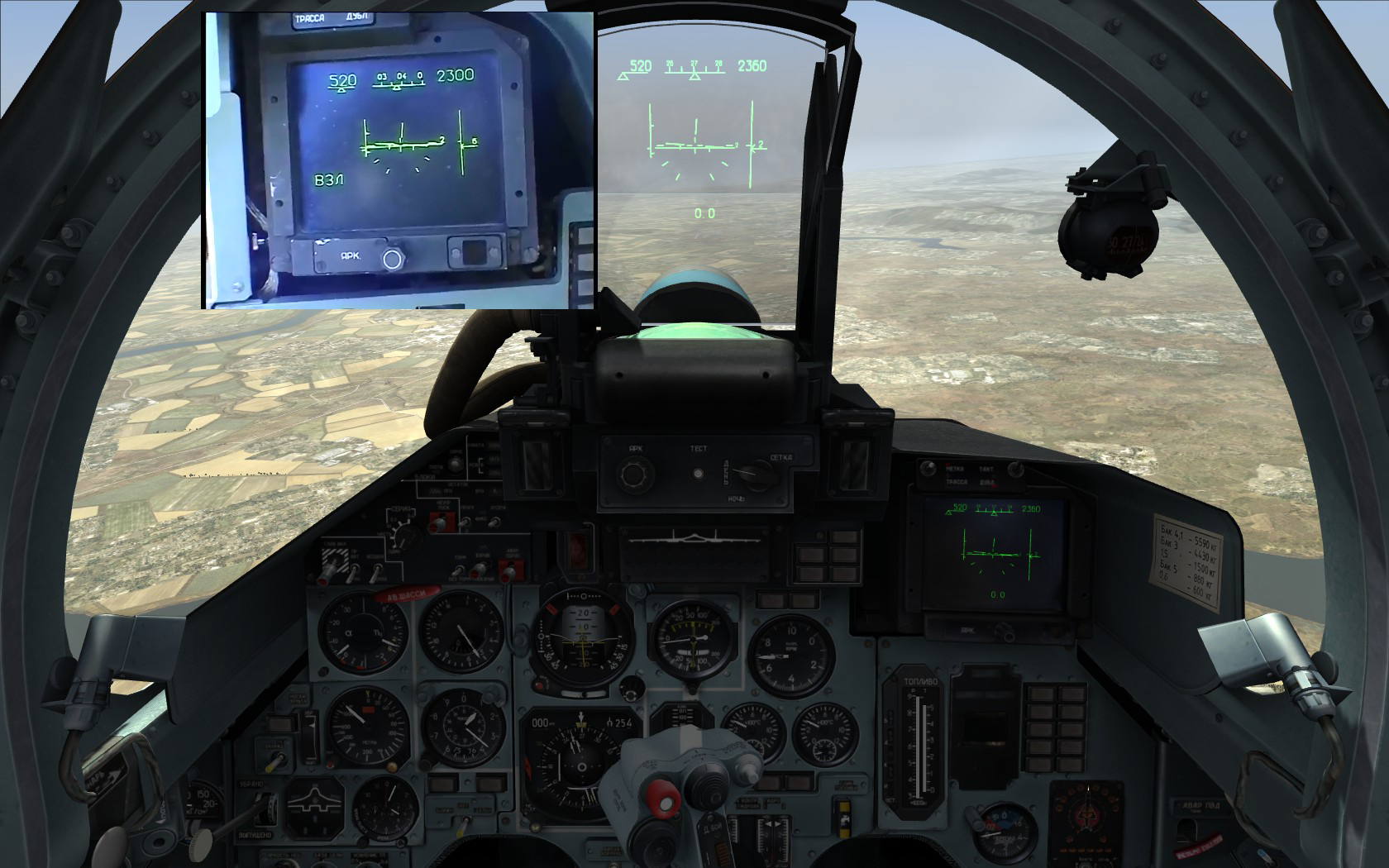
I have tried to recreate flight condition seen in this video at 2’29’’ Speed 520, altitude 2300, pitch angle 2. I have used close to 100% fuel, just to make the AoA higher. See the image below. The cockpit indicator shows about 3 deg AoA. The AoA indicator in the video is at about 25% between zero AoA and max AoA. Assuming the upper mark corresponds to 10 deg would mean the AoA is 2.5 deg – that seems close to my experiment. If we assume the upper mark corresponds to 24 deg like in DCS that would mean the AoA is 6 deg – that is way too much for current flight condition. At 6 deg AoA in those conditions the aircraft would be pulling more than 1G – notice in the video the pitch angle changes so slowly, it can be considered constant. The aircraft in the video was at very close to 1G. I repeated the experiment at very low fuel level – AoA was about 2 deg. In my video capture included in the screenshot the vertical velocity shows -6m/s descent, while my experiment shows -2, that is because FC aircraft don’t have variometer delay. Notice that in the video the descent rate reduces continuously. Minor differences between AoA scale in DCS and real aircraft: - on the real aircraft the left “zero bank angle/AoA reading index” mark is touching the AoA scale - the gap between zero AoA mark and min AoA mark is smaller - the horizon line is crossing the AoA scale - the AoA scale is shorter

-
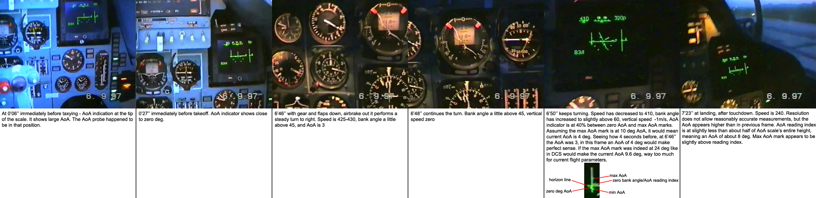
I don’t think the AoA indicator on HUD is working correctly. Precisely, I don’t think the upper mark on the scale should correspond to 24 deg. On the real aircraft, AoA indicator appears only in display modes “Takeoff” and “Landing”. In DCS we don’t have a “Takeoff” mode, but we have a “no-selection” mode. I don’t think the indicator on the real aircraft was intended as an aid to allow performing aerobatics “HUD only”. It appears only in “Takeoff” and “Landing” modes – in takeoff/landing configuration the real aircraft is restricted to 20 deg AoA. Why would they put a mark on the scale at 24 deg, when you shouldn’t exceed 20? In “Takeoff” mode I think the role of the AoA scale is to help the pilot during rotation. The Su-27 has a pitch angle indicator on the HUD of a type that provides poor pitch rate awareness. So the AoA indicator is helpful in this case. I am 99% sure that in “Takeoff” mode the upper mark on the scale corresponds to 10 deg AoA. The manual recommends 10 deg pitch for takeoff – you rotate until the AoA reading index on the HUD is at the upper mark on the scale. And here is also the explanation why the AoA scale extends so much above the upper mark – because the upper mark corresponds to 10 deg only, not 24. In “Landing” mode the AoA scale’s role is more like to display how much AoA “reserve” the aircraft has for approach, flare, touchdown. I believe in “Landing” mode the upper mark on the scale corresponds to 12 deg instead of 10, however I can’t demonstrate that. But it is worth saying that in the flight manual the landing speed diagram clearly states it is for a 12 deg AoA at touchdown. In the image below I analyze what can be seen in this video In the video the aircraft is an Su-27UB, but it doesn’t matter. The “Takeoff” and “Landing” display modes are similar. I think the pilot in the video selected “Takeoff” display mode for landing because he didn’t wanted to make a slower landing, with 12 deg AoA at touchdown. It was not necessary. So he preferred to have the AoA indicator on the HUD show him 10 deg as a reference.
-
L0op8ack, many thanks!
-
I think you are right about both issues. It’s true, in full AB the nozzle opens a little too much when compared with what you see in pictures, which is usually at low altitude and subsonic. However this full AB nozzle opening shouldn’t be constant in the entire flight envelope. At Mach 2+ in stratosphere, I would expect it to be pretty much fully opened, in order to ensure as closely possible to full exhaust gas expansion in the thinner air (full expansion is probably not possible at high altitude, the diameter of the exit area of divergent nozzle flaps would have to be pretty huge). That’s why most likely the nozzle will be fully opened in such conditions. The louvers – I had the opportunity to see with my own eyes Su-27 performing aerobatics, and it is clearly visible how the louvers are individually flapping around quite a lot. They are free floating and open according to pressure differential inside/outside the intake. Generally, they tend to open at high thrust settings and medium to high AoA, but not exclusively. My opinion – a convincing AoA-related animation for the louvers could be done.
-
^^^ Where from can I get such telemetry?
-
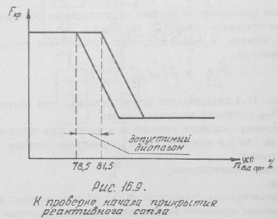
I did the following experiment (track attached): with 3% fuel, standard conditions, I accelerated the plane, reduced throttle to idle and timed how long it needs to decelerate from 50 Km/h to zero. Result: 46 seconds. I accelerated the plane again, then reduced throttle to open the nozzle, then advanced throttle to 78%, the highest rpm possible with an open nozzle. Deceleration from 50 Km/h to 0 took again 46 s. This can’t possibly be right. It’s true, pretty much any jet engine with a completely open nozzle will have quite a low idle thrust, but still increasing the rpm by 9% from 69% idle to 78% can’t have zero effect on thrust. I turned the plane at the end of runway and accelerated again, then both engines OFF. By the time the speed dropped to 50 Km/h the rpm of both engines was 0. Deceleration from 50 Km/h to 0 took 50.5 seconds. This would seem to suggest the idle thrust actually has a negative value! It’s true, in flight engine thrust might actually have a negative value in some limited part of the envelope, but I wouldn’t expect it to be negative at close to standing still speeds. In AL-31F engine technical manual you can check here http://airwar.ru/other/bibl/al-31.html on page 9 they state the engine’s idle thrust, 250 Kgf, and they also very clearly state the value is with the nozzle opened. In order for my 3 little experiments to make sense, the average thrust in the 0-50 Km/h range would have to be negative. It would imply that, from a standing still thrust of 250 Kgf per engine, starting moving the plane the thrust quickly, within a few Km/h would get zero and then negative. I don’t see that happening, having checked a diagram for the entire envelope for idle thrust for RD-33 engine that is principially identical and also uses a very wide opened con-di nozzle setting for idle in order to minimize idle thrust, just like AL-31F engine. I also did another deceleration test (didn’t attached the track here) with engines idle then OFF, at 7 Km altitude and reached the same conclusion – currently in the simulation engine idle thrust has a negative value. Again, comparing with available data for RD-33 engine, at 7 Km altitude the idle thrust is indeed pretty low in subsonic where I did the test, but is positive. See this video here Starting from 2m8s the aircraft is taxiing, the left nozzle is completely opened, while the right nozzle is very slightly closed. I was intrigued when I saw that, knowing from DCS that during taxi the nozzle can be either opened or closed. So I checked the same AL-31F manual. See image 1 below. Under the diagram they say “At checking the beginning of closing of the jet nozzle”. On the diagram it says “the admissible range”. In the text they say the nozzle will begin closing at an rpm of 80%+/-1.5%, so this is the “admissible range” in the diagram of 78.5 to 81.5%. ED has chosen 78.5% as the value at which the nozzle closes. Maybe it would have been more logical to choose 80%. Also check in the diagram on x axis, the value is named “n вд пр”. This is the temperature-corrected high pressure rotor rpm. Meaning the nozzle would start closing at 80%+/- 1.5% at an outside air temperature of 288K (15degC, standard conditions). At higher outside temperatures, the nozzle closing would begin at an rpm a bit higher, while al lower temps – at lower rpm. What’s the most interesting info in the diagram – there is a range of rpm in which the nozzle goes from fully opened to fully closed. I couldn’t find precise info in the text, but assuming the diagram has reasonably accurate proportions, it would suggest a range of about 5%. In image 2 you can also see for nozzle area (Fкр) there is a range of throttle positions where it goes from fully opened to fully closed. Currently in DCS when reducing throttle, the nozzle would open at about 73% rpm. I couldn’t find anything in the manual to support that, which would seem to suggest that on reducing throttle the nozzle would follow the same digram as when increasing rpm. But maybe ED has additional info about that. What I described above goes some way to explain the annoying technique required to taxi the aircraft (engine management-wise), and also why it is ridiculously difficult to fly formation al slower speeds. Because in the lower rpm range you have only 2 engine thrust options: no thrust or too much thrust. In reality the things would go something like that: at idle, 250 Kgf thrust per engine (instead of right now negative thrust). Increasing the rpm towards 80%, the thrust would increase, it’s true, not spectacularly because of the fully opened con-di nozzle. But it would increase anyway. Reaching 80%, nozzle would start closing and advancing throttle more the thrust would increase considerably more abruptly, but not suddenly like in current sim version, but in a range of about 5% rpm. Reaching the fully closed position, advancing throttle further, the thrust will increase more. During taxiing, reducing throttles to idle – you would still have half a tonne pushing the aircraft. The speed would probably decrease pretty slowly. At low aircraft weight, it might even be possible to taxi the aircraft at constant slow speed with open nozzles, if it’s already at 20-30 Km/h, that’s something I can’t estimate. Generally, engine simulation in current version is very basic. On the ground, the engine idle rpm is constant, no matter what the outside temperature is. It should increase with increasing temperature. At Mach 2+, you reduce throttles to idle – the same 69% rpm as on ground. According to AL-31F manual, in such conditions the idle rpm would be about 97%. The rpm in military and afterburner is not constant in the entire envelope on the real aircraft. Also propulsion related – there is no air intake compression ramps animation and no ramps position indication in the cockpit. There is still a lot to be done regarding engines before the simulation is at the level where it should be, and I hope it would be one day. 1.trk
-

Su-27 - Comparing flight model with real life numbers
Fox One replied to Fox One's topic in Su-27 for DCS World
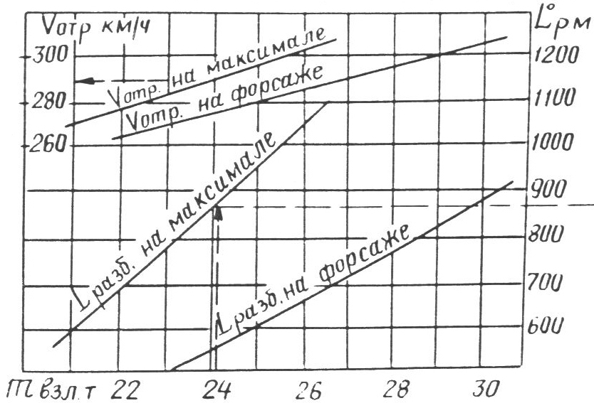
^^^ The aircraft got airborne at 300 Km/h (and you had no missiles). I had an idea for another test. In first post in this thread I posted a diagram that shows for a weight of 25 tonne (95% fuel and no stores in DCS) the liftoff speed is 280 Km/h. See attached track for the test. Took off with 100% fuel, burned 5% fuel, landed the plane, aerobraked for a while, then engaged full afterburner, maintaining a pitch angle of 10 deg (as recommended for takeoff by real flight manual). The aircraft got airborne at approx. 275 Km/h. This is very close to what the diagram shows. For an AoA of 10 deg the lift plus vertical component of engines thrust equaled 25 tonne at 275 Km/h. This is great, it shows the aerodynamic characteristics of the flight model in takeoff configuration is pretty much spot on. The real problem here is that, for whatever reason the aircraft can’t be rotated soon enough (or with a pitch rate high enough) to be able at 25 tonne weight to attain a pitch angle of 10 deg NO LATER than when the speed is 280 Km/h. This is the only problem here. The lift produced by aircraft in said condition appears very accurate. 27TO1.trk -
There is no mention whatsoever in flight manual for real aircraft that brake chute deployment is locked when airborne.
-
[User error] Su-27 gear doesn't retract properly
Fox One replied to kontiuka's topic in Su-27 for DCS World
Flight manual for real aircraft says very clearly that maximum speed for extension, retraction and flight with lowered gear is 500 Km/h. If the manufacturer says so, I would expect when flying horizontally at 1G with 460 Km/h the gear would retract. Currently it does not. -
Su-27 - Comparing flight model with real life numbers
Fox One replied to Fox One's topic in Su-27 for DCS World
If you can do that please post a track, because I surely can't do it. What has trim to do with what's being discussed here? The manual for real aircraft says trim in all 3 axis must be neutral before takeoff. You can apply before takeoff all trim you want, if you think that will magically increase the stabilator max deflection angle available you're completely wrong. -
The first thing I noticed about the flight model – it is too hard to rotate the aircraft during takeoff. See the diagram below. For a weight of 25 tonne, taking off in afterburner the aircraft should lift off at 280 Km/h. My experiment (track attached) – with 25 tonne weight (95% fuel and no stores) in standard conditions, switched on full AB, at 200 Km/h pulled the stick fully aft and kept it like that until the aircraft was airborne. The nose wheel lifted at 300, the main wheels lifted at 330 Km/h. That’s 50 Km/h more than what the diagram shows! How can I be airborne at 280 when the aircraft doesn’t want to lift nose wheel until the speed is 300? I did some more similar experiments at lower weights – it seems to me like the lower the weight, the closer it gets to what the diagram shows. 27TO.trk
-
Su-27 Open-Beta chit-chat and first impressions!
Fox One replied to JulienBlanc's topic in Su-27 for DCS World
The first thing I noticed about the flight model – it is too hard to rotate the aircraft during takeoff. See the diagram below. For a weight of 25 tonne, taking off in afterburner the aircraft should lift off at 280 Km/h. My experiment – with 25 tonne weight (95% fuel and no stores) in standard conditions, switched on full AB, at 200 Km/h pulled the stick fully aft and kept it like that until the aircraft was airborne. The nose wheel lifted at 300, the main wheels lifted at 330 Km/h. That’s 50 Km/h more than what the diagram shows! How can I be airborne at 280 when the aircraft doesn’t want to lift nose wheel until the speed is 300? I did some more similar experiments at lower weights – it seems to me like the lower the weight, the closer it gets to what the diagram shows.
-
F-86F flight manual: “To obtain initial taxi roll, open throttle to approximately 60% rpm; then retard throttle immediately. Once the airplane is rolling, it can be taxied at idling rpm on hard surface.” The aircraft with 100% fuel and no external stores (in standard conditions) will not move at 60% rpm, it will require about 63-64% rpm. The aircraft will barely move at 60% rpm with a very low fuel quantity (like below 25%) and no external stores. Once the aircraft is moving, reducing throttle to idle – the aircraft will stop, no matter how low the weight (even with 5% fuel, no stores), at any outside temperature. In the flight manual after engine start they say engine idle should be between 34% and 38% rpm – in DCS idle rpm at outside temperature -/+ 50deg C is 26% to 31% rpm – completely outside the range specified in the manual. I believe currently in DCS the rpm/engine thrust correspondence at idle and also intermediate rpm is inaccurate. Or it might be that wheel drag is too high, though I doubt this is the problem here.
-
In my previous post I said the F-86 when applying rudder and keeping the wings level it will fly straight in this yawed state. I stand corrected – the aircraft actually performs a flat turn, but it is so slow, it is barely perceptible. I did some more testing and found another thing. I accelerated the plane at low level using military power, it accelerated to 1130 Km/h in external view. Then I slowly applied full rudder, while keeping the wings level. You’ll never believe what happened (or maybe you will…) The speed remained 1130!!!!!!!!! How on earth could that be realistic? I made a screenshot from above and from it measured the beta angle – it was approx. 4 deg. At such a speed (M0.93) at low level and 4 deg beta angle the sideforce generated by the fuselage side facing forward can’t possibly be a close to a negligible amount. And there is also the sideways component of engine thrust, an elementary calculation shows this only should amount to close to 200 Kgf. But IMO the sideforce produced by the fuselage in this particular case should amount to maybe even more. I remain convinced the almost imperceptible flat turn the plane does in this situation is much too slow. I also noticed in my experiment that I was able to deflect the rudder fully. The rudder is not hydraulically actuated. At 1130 Km/h at low level the force necessary to deflect the rudder fully is measured in hundreds of Kgf. How could possibly a human deflect the rudder fully? In other planes without hydraulically boosted controls (P-51, Fw 190) if you try to deflect rudder or ailerons at high speed they will not deflect fully – the maximum force a human can exert on the controls is obviously simulated there. Nevermind that if the rudder was actually hydraulically boosted, deflecting it FULLY at low level and M0.93 would probably brake the vertical fin. Most planes with hydraulically boosted rudder actually have some rudder limiter, at hight speed full rudder is not available (or is available while exerting a very high force on rudder pedals to overpower the limiter). And since the subject here is F-86 rudder – when using rudder trim the trim itself in outside view will deflect correctly, however the rudder will remain centered (in flight, of course) and there is no rudder effect noticeable.
-
Precisely this. Derelor, do the following experiment: with the A-10C, while flying at a moderate speed, gradually apply full rudder, using the ailerons to prevent the aircraft from banking. The aircraft, slowly but surely will perform a flat turn. This kind of behavior is to be expected from pretty much any aircraft in the world. Now do the same experiment with F-86 (also F-15 if you want) - the aircraft in this yawed state keeps flying straight. Very weird. I might be wrong, but I think what's missing from the flight model for F-86 and F-15 is the sideforce produced by the fuselage in a yawed state.
-
Wags avatar is an IPV display from a standard Su-27, switched to TAKT. (tactical) mode. I did some computerized analysis :D of the display's lower frame and concluded it's the same texture that is right now in Su-27 cockpit so that's an in-game screenshot. I can only think of 2 variants: 1) FC3 Su-27 is getting improvements 2) Full DCS level Su-27 is coming My vote is for 1)
-
Below is a picture of the unrestored cockpit of Ta-152H. On the label above radiator flaps control wheel (Kühlerklappen) there is Auf on left, Zu on the right and in the middle Automatik. In Ta-152H pilot notes they say before takeoff the pilot should put radiator control in position 100°C. I can only assume the Automatik mid position is the 100°C position they mention in pilot’s notes. In Jerry Crandall’s Fw 190 Dora book, vol 2 page 15 they quote some flight test documents for D-11, 12, 13 and somewhere they mention for the climb performance coolant datum 100°. I believe the radiator flaps control and the way the system works in Dora is similar with Ta-152H, however I’m not 100% sure yet. Here you can see the label for radiator flaps control wheel for D-9: http://forums.eagle.ru/showpost.php?p=2168441&postcount=26 The “Automatik” position isn’t marked. However, that does not necessarily contradicts my theory above that D-9 radiator flaps control is similar with Ta-152H. The mid position on D-9’s label above the control could simply be unmarked. The mid Automatik position on Ta-152H implies that the control wheel must have a tic mark on it and it can’t be rotated left or right more than one full turn. Otherwise the central “Automatik” position wouldn’t make any sense. But let’s ignore all possible similarity with Ta-152H. The radiator flaps control as it is now in DCS Dora – you need to turn, turn, turn it for a long time. I might be wrong, but I find this unlikely to be realistic. I say that mostly because the control is not placed in an easily accessible location. If there was really necessary to turn it like that for a long time, they would have made the plane half a kilogram heavier and placed the control within easy reach.
-
^^^ Create a folder named F-86F Sabre in this location: DCS World\Bazar\Liveries Put there all skins you want
-
^^^ Rudder Randomizerer :megalol:
-
That is right. F-15 and F-86 are the only DCS planes having this problem. Something is definitely missing from the flight model equation here...
-
Landing the A-10C in manual reversion instructional video
Fox One replied to Raistlen007's topic in DCS: A-10C Warthog
I find it absolutely unbelievable that after all those years, they still haven't fixed the pitch trim working in reverse in manual reversion mode. -
There are several minor cockpit inaccuracies, but there is only one that actually annoys me each time I see it. See the image below. The red line is at the lower edge of the auxiliary instrument panel. See how the two indicators are actually only slightly too high in relation to the line. Moving the indicators, oxygen valve and flare gun port lower the correct amount won’t make this area accurate, because the problem unfortunately is a much more serious one. From the image it is very obvious the entire area is actually too tall. It’s definitely not a matter of the instruments being too small, I investigated that. I understand making major geometry changes in the cockpit at this stage must be a firm “NO GO” from ED. While I’m no 3d modeler, I was thinking maybe moving lower the 4 items won’t be an enormously difficult thing to do. Modifying the auxiliary instrument panel texture is something simple, even I could do. To make this area look more accurate without major geometry changes in the cockpit would require IMO to make a little compromise. Move the 4 items deliberately a bit lower than they should be in relation to the red line. Oxygen valve should be lower than oxygen pressure indicator. The idea would be to make that space appear less huge, and at the same time not make another huge empty space appear above them instead. Anyway that space above is a lot less visible. A clever compromise is needed to make the area appear more accurate.