Fox One
-
Posts
447 -
Joined
-
Last visited
-
Days Won
2
Content Type
Profiles
Forums
Events
Everything posted by Fox One
-
Thanks IvanK, I have the EZ 42 manual too, but I haven't studied it yet because I can't read any German. I just looked at the pictures :D
-
Please provide details about locations and where they are stated.
-
Please read this: http://forums.eagle.ru/showpost.php?p=1818980&postcount=422 The EZ 42 adjustment box was located on the left side of the cockpit, probably close to the rear cockpit bulkhead. About MW 50, I'm not sure it will have the system. But if it will have it, they will add the engagement switch so I wouldn't worry much about the missing control from the cockpit screenshots.
-
Where have you seen such a stick handle on Su-25?
-

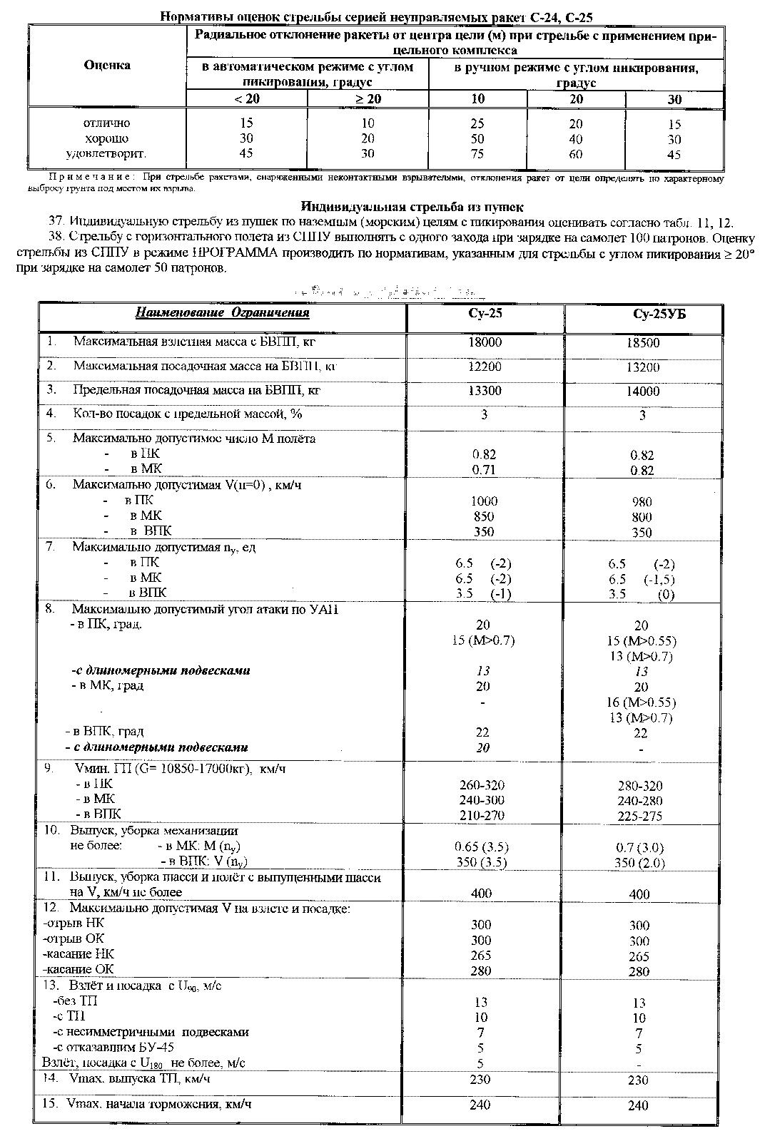
Max landing crosswind for Su-25/Su25T?
Fox One replied to Esac_mirmidon's topic in Su-25 for DCS World
For Su-25 and 25UB: 13. Takeoff and landing with U90, m/s: -without drag chute 13 - with drag chute 10 - with asymmetrical stores 7 - with malfunctioned BU-45 (ailerons hydraulic actuators) 5 Takeoff, landing with U180 (wind from behind), no more than 5 m/s.
- 1 reply
-
- 2
-

-
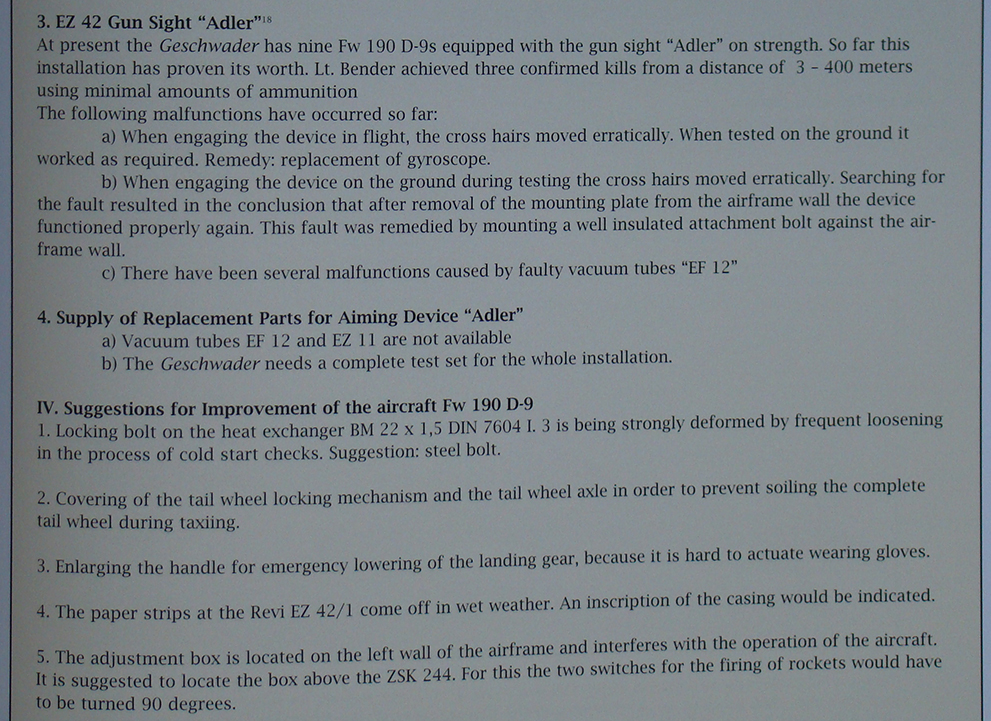
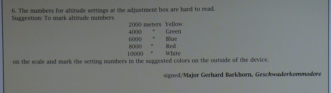
Interesting operational report about Fw 190 D-9 equipped with EZ 42 from JG 6, signed by Gerhard Barkhorn. From Jerry Crandall's Fw 190 Dora book.
-
I don't think it will have MW 50. The activation switch and other associated controls are missing from the cockpit. What's interesting is that it will have EZ 42 gunsight and not the common Revi 16 ...
-
So... nobody noticed in Yo-Yo video that the Fw 190 jettisoned a Mustang canopy ? :D
-
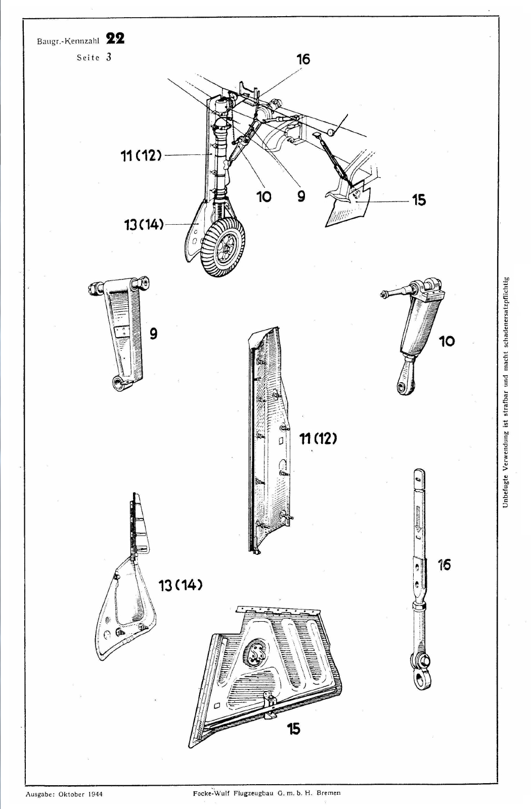
Oh, I see now what you mean, silly me. You don't see the small part in the diagram because that diagram, as the one in the picture below, is from Fw 190 D illustrated parts catalogue dated Oktober 1944. As you can see, the plane initially was configured with doors closing over the wheels (part 15 in the pic below). Here you can see a great picture of a D-9 prototype: http://forums.eagle.ru/showpost.php?p=1749268&postcount=342 See the doors closing the wheels close to the centerline of the plane, also check the landing gear doors shape ... yes' that's right, that little part on the lower side of the gear doors is missing. Also, see the central flap of the radiator - it's opened, this was closed shut on serial D-9, this is a prototype. However, for serial D-9 they gave up using the central doors closing over the wheels, and they added the small part I was talking about in my previous post in order for the wheel to be better covered when retracted. But the illustrated parts catalogue was already made with drawings showing the landing gear doors configured like the prototypes :)
-
This is true. In the left picture fantomk posted, the difference in shape is because the lower part of the gear door was removed. This was done sometimes, like you said, in muddy airfield conditions. Otherwise, in the specified picture is a very normal D-9. However, it was something relatively rare to be seen on D-9. Of all the pictures in all the books I've seen, I don't think I saw more than 10 pics with Fw 190 D-9 configured like that. @Merlin-27 - there weren't several varieties of landing gear doors on D-9. All D-9 built were identical regarding gear doors.
-
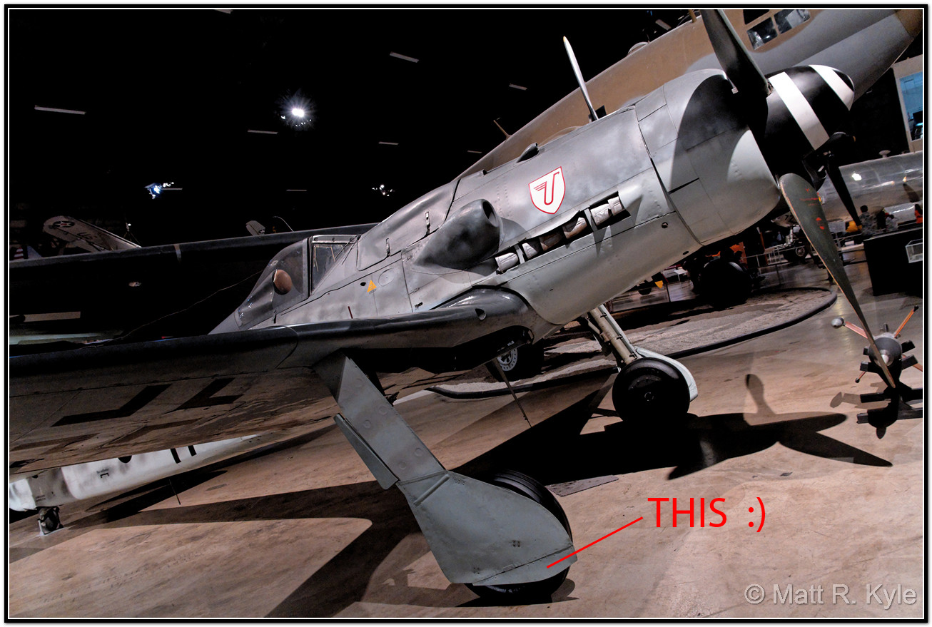
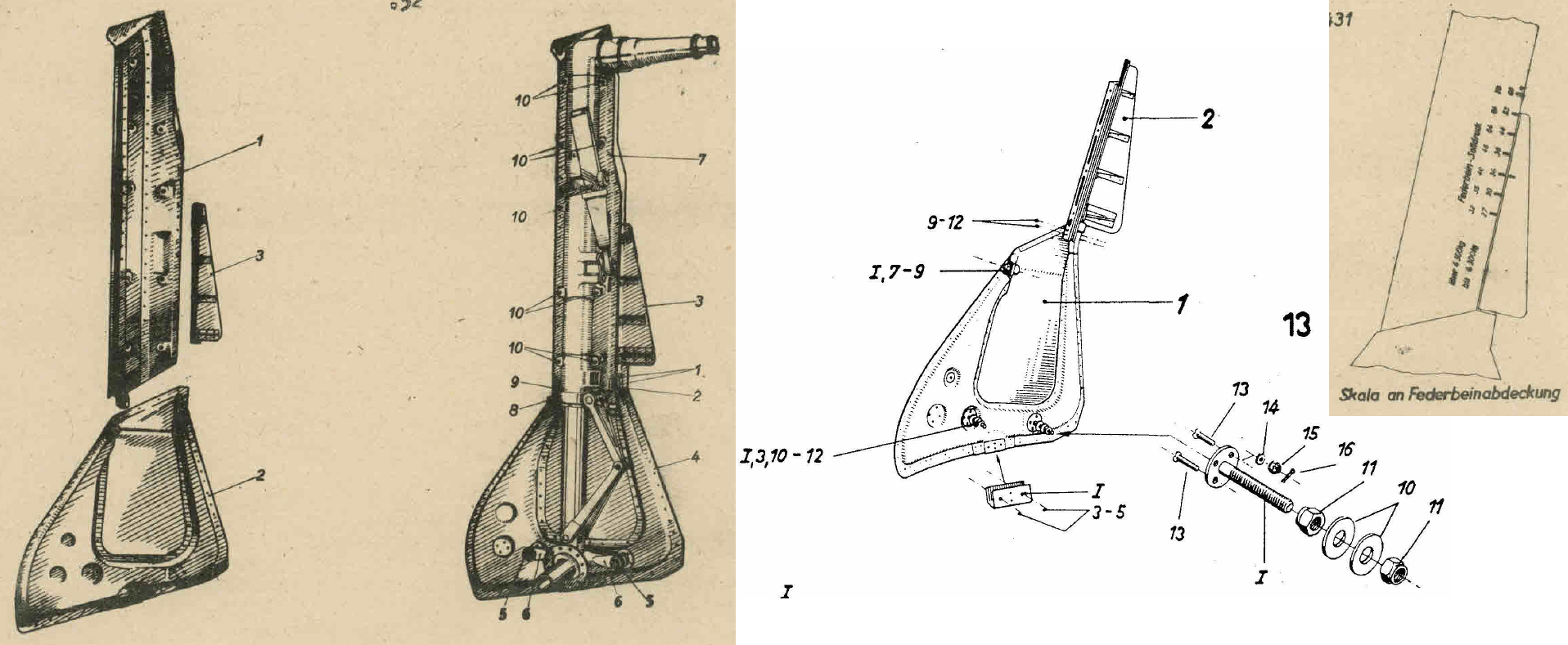
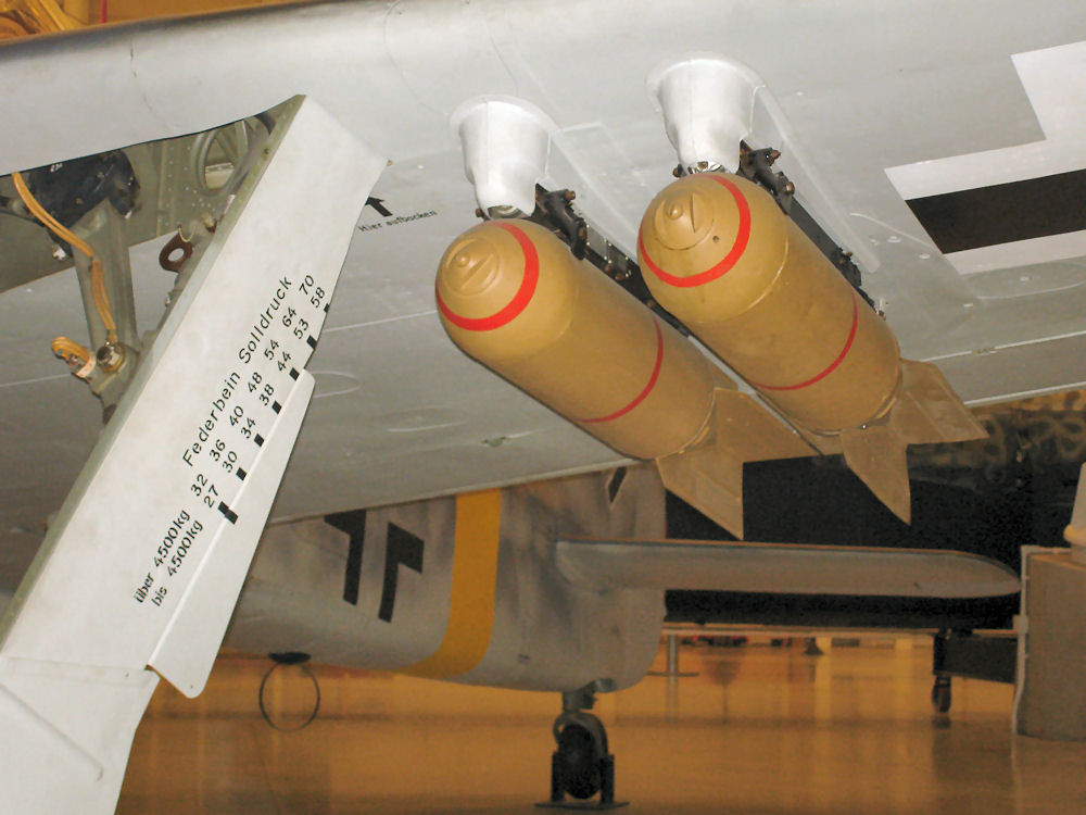
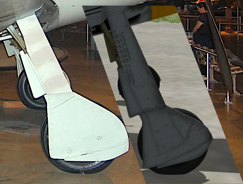
Actually, when I posted that picture with the landing gear, my idea was rather to compare with the DCS model the lower part of the gear door, where the inaccuracy in DCS model is very obvious. The gear door is not a single object, but actually 3 :) Please look at the first drawing on the left. Part 2 is attached to the lower part of the shock absorber. Part 1 is attached to the gear leg itself. As you can see on the drawing in the middle, part numbered 3 in the first drawing on the left is also connected with part 2. When the shock absorber is compressed, part 1 "slides" inside part 2, and part 3 slides up on the edge of part 1. On the drawing on the right, you can see how on the outer side of parts 1 and 3 there are check markings for various plane weighs. You can see the markings also on the picture of an F model. I specify that all drawings are from manuals for Fw 190 D-9 and not earlier versions. The difference in length that you noticed is because on the D-9 plane in US museum shock absorbers are very compressed, possibly fully compressed probably due to lack of servicing. Indeed, in the wartime pictures you posted it's visible the correct position of a serviced, airworthy Fw 190. Otherwise, there is nothing weird or wrong with the museum D-9, the gear doors are original, is just that the shock absorbers position is abnormal.
-
More about the windshield and canopy:
-
The antenna wire - the plane in DCS is fitted with a late-type, so-called "blown canopy". On this type of canopy, there is no antenna pulley system like it was in earlier Fw 190 models. The wire is rigidly attached to the canopy, so after opening the canopy, the antenna shouldn't remain straight like in the Mustang.
-
Yes, you are right, the pilot should jettison the canopy, not open it. I noticed it too, but I thought that the canopy jettison must be WIP and not implemented yet so I didn't mentioned it, I imagined that ED knows the canopy is jettisonable. In reality the pilot would only open the canopy if the jettisoning system failed. I remember I read about that in one book, the pilot had to manually open it to bail out. Opening it would normally take considerably longer than jettisoning.
-
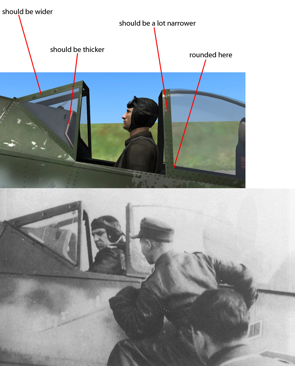
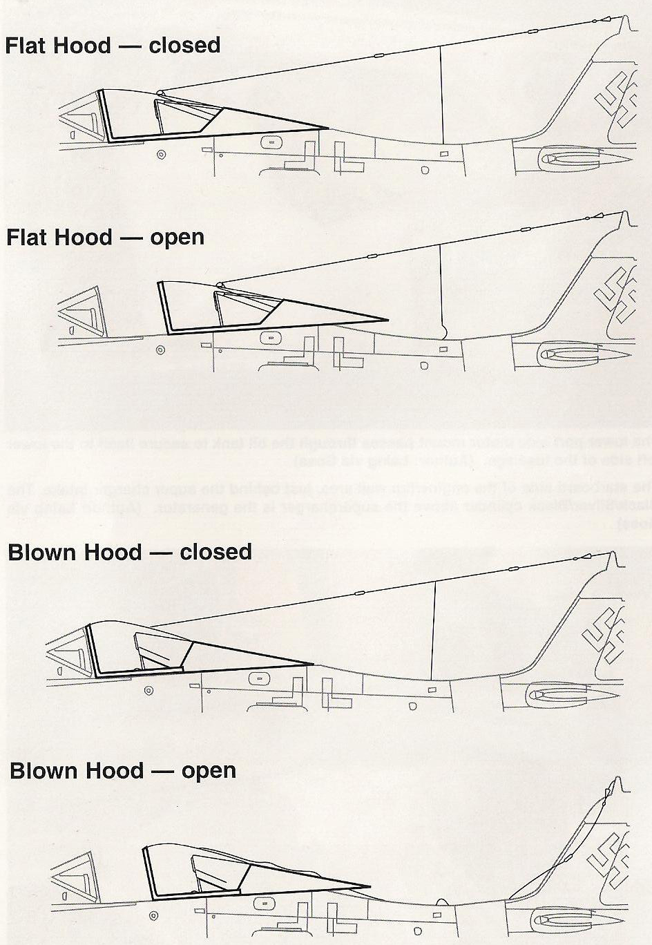
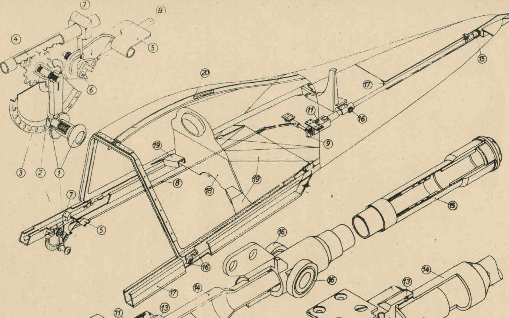
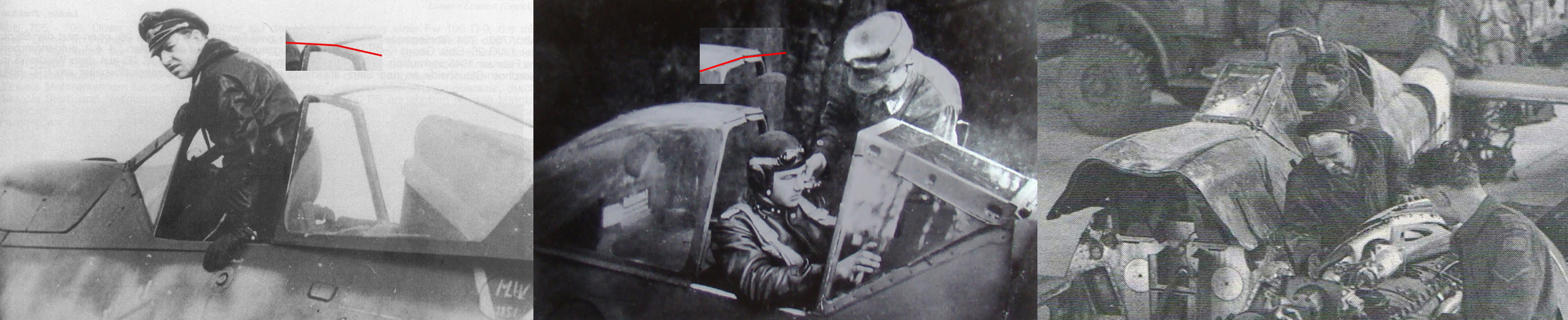
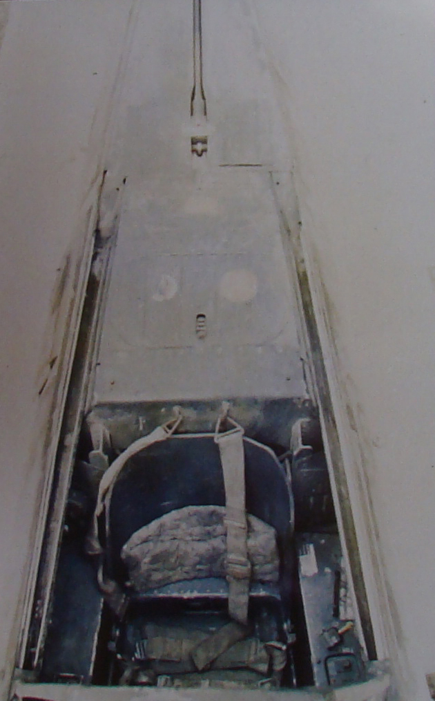
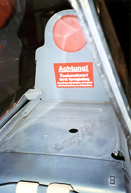
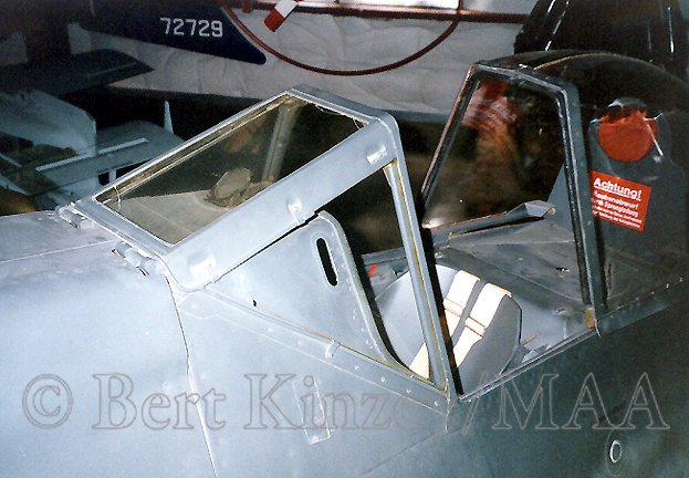
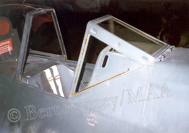
An interesting thing about Fw 190 canopy. Have a look at the drawing below, it is from a technical book. On the canopy sides there are the rollers 16 that run inside two troughs placed right on the edges of the fuselage. There are also other rollers more to the back of the canopy that run in a central trough, but that's not important now. As I said, the troughs are right on the edges of the fuselage, but going from front backwards the fuselage gets narrower. So the lateral troughs are actually not parallel, they are converging towards the tail of the plane. When opening the canopy, as it travels back, the distance between the rollers on one side and the other of the canopy gets smaller, so to be able to complete the trick the canopy actually "bends" from the middle. The forward metallic part of the canopy has a hinge right in the middle. The metallic part running through the center of the canopy has a cross-sectional shape like an H letter, and inside the H there are the edges of the two plexiglas halves of the canopy, but they are not fitted rigidly inside the H, they are mounted probably using some sort of rubber so they can tilt slightly inside that H. When the canopy is jettisoned, the shotgun in the middle of the canopy pushes it back. At the end of the lateral troughs there are some sloped parts, the lateral rollers "climb" those ramps and the canopy separates from the aircraft. It's not easy to find D-9 pictures with the late-type canopy where the "bend" in the middle of the canopy is visible. I did the best with what I could find, on the left and center pictures are D-9 with late-type canopy. On the right is a D-9 with early-type canopy, but that doesn't matter, the canopy principle is the same. You can see in this picture that, because the canopy is opened all the way to the back, the "bend" is very obvious. Also, on the technical drawing there are the articulated rods 19. Because the canopy actually gets narrower while opened, the back armor is attached to the canopy frame with 2 articulated rods similar with Fw 190 planes with early-type canopy, the only difference is that over the rods there are some metallic farings. In the last pictures you can see the lateral troughs on the fuselage of the D-9 and also the jettisoning "shotgun", and the last 3 colour pictures are actually of an F model, but obviously it is fitted wit the same late-type canopy as the D-9. The shape of the covers over the back armor's articulated rods is clearly visible, as is the slight canopy "bend" in the middle. The conclusion is - in order to have an accurate canopy in DCS Fw 190 model, the canopy actually has to basically "change its shape" slightly while opening or closing it.
-
Landing gear doors:
-
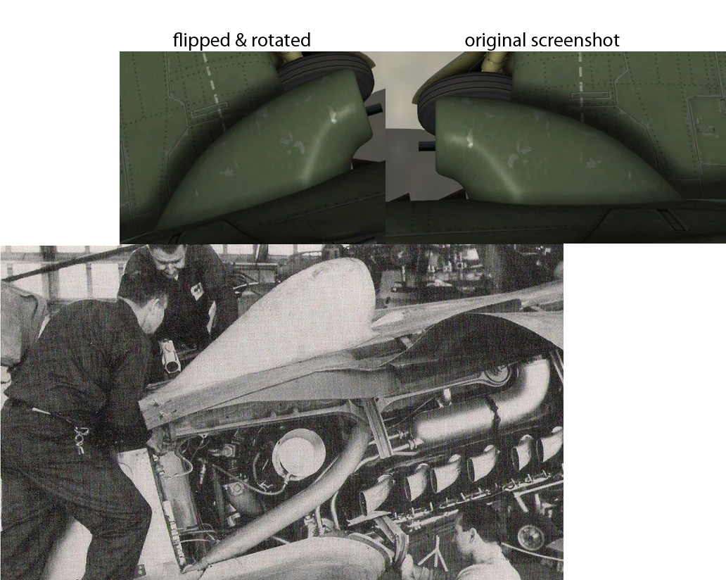
Thanks, those pictures are actually known for me from long ago. Why I have used that particular b/w picture of the scoop, despite its not great quality - it's because it depicts the scoop as it would appear in a longitudinal section through the middle of it. I honestly thought it was evident. It's not easy to find such a picture, pictures from a random angle there are plenty.
-
The plane in the scoop picture is Fw 190 D-9, W.Nr. 601088 while undergoing restoration in the US. The air scoop is original, while on the Fw 190 D-13 "Yellow 10" W.Nr. 836017 (fitted indeed with the bigger, oval scoop) that is also displayed in a US museum, the scoop is a replica (and not exactly a great one...) The point is the difference between the D-9 intake and the bigger one fitted to the later D models is pretty obvious, also in the picture the engine is a Jumo 213A with the associated engine mount, and not a Jumo 213E or F with a different (bigger) compressor intake and very different engine mount.
-
The air intake scoop. First, it is not easy to make a screenshot in DCS of the air intake from below to perfectly match what's in the picture, because the wing is in the way. So I took a screenshot from above, then flipped it. Anyway, that doesn't matter - what I'm trying to point out here is the scoop's contour shape, which is similar when seen from above or below. It is obvious the scoop is too bulky and generally inaccurate.
-
[REPORTED] Distance between MG 131 [0027499]
Fox One replied to Fox One's topic in DCS: Fw 190 D-9 Dora
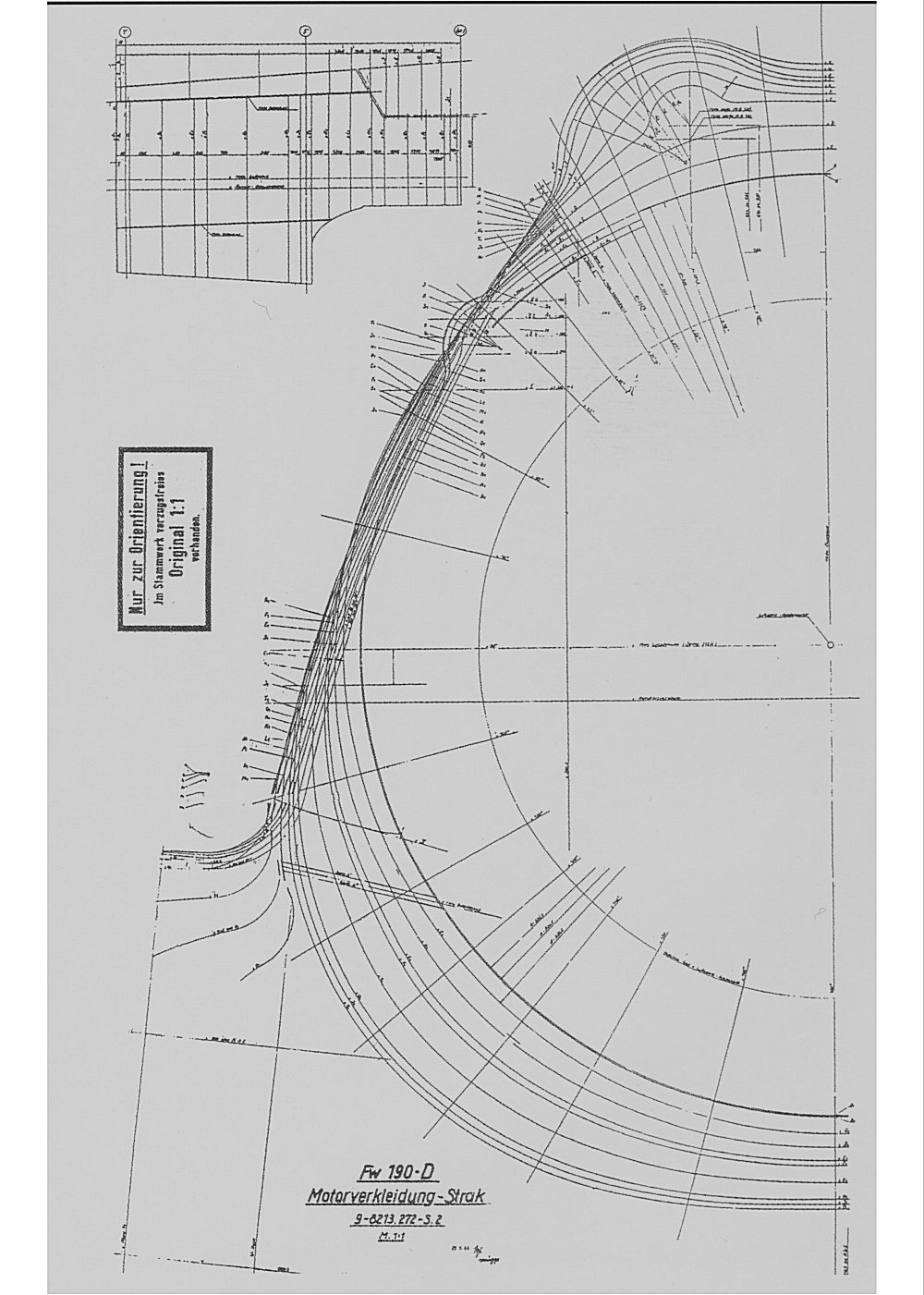
The drawing was posted on another forum. The only place I've seen that drawing is Jerry Crandall's "Fw 190 Dora" book, vol. 2. I'm 99% sure the poster scan it from the book. -
[REPORTED] Distance between MG 131 [0027499]
Fox One replied to Fox One's topic in DCS: Fw 190 D-9 Dora
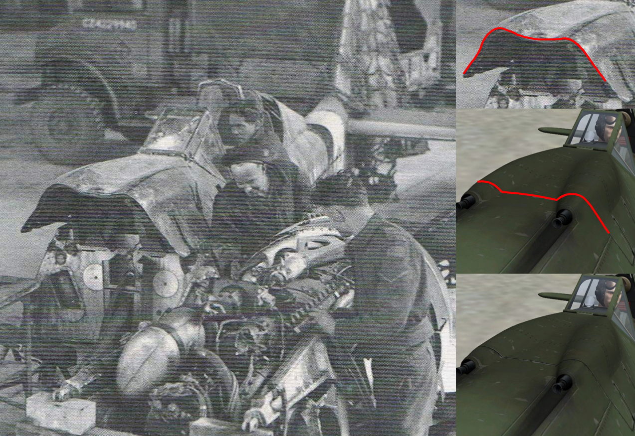
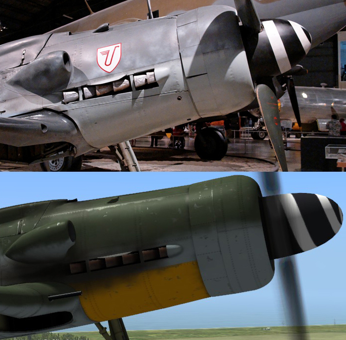
MG 131 guns cowling's cross-sectional shape. Compare the shape of the forward edge of the cowling in the picture with the screenshot from DCS. I have also posted a technical drawing showing the cross-sectional shape of the forward part of the cowling, very useful just in case someone will bother to correct it. As expected, it matches the cross-sectional shape seen in the picture.
-
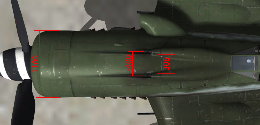
Another thing I noticed on the Fw 190 model - the distance between the MG 131 guns is too big. Personally I'm convinced of that, for me it's visible with the naked eye. However, here is my little demonstration attempt, as imperfect as it might be. The real plane radiator cowling's diameter is 1100mm. My demonstration is based on the assumption that at least this important dimension is accurate on the model in DCS, anyway it doesn't look like it's too small. The distance between the MG 131 guns should be 308mm. According to my measurements in the picture below, the distance as is now is approx. 400mm. I have drawn also how close the guns should be. While taking the screenshot used, I have tried as best as I could to minimize the errors. Anyway, the difference is too big to be put down on perspective errors.
-
I must say I was expecting more regarding Fw 190 model accuracy. I hope at least the most obvious shape errors will be corrected. Especially considering that in the future the Fw 190 will be a flyable plane, I suppose ED's intention is to try keep a high standard. It really saddens me that the person who built the 3D model, obviously didn't knew which are the most accurate scale drawings available for the plane (I mean drawings really, really close to perfect). I'm sure a lot of the errors would have been avoided. First I have a humble suggestion to ED, to change the name in the sim from FW-190D9 to Fw 190 D-9. That's how the plane's name was written in any WWII German documents. The first thing that I would improve on the 3D model is the radiator's forward cowling. Its shape is very obviously inaccurate.
-
PLAAF, you might like this La-7 technical description book: http://airwar.ru/other/bibl/la7to.html La-7 flight testing report: http://airwar.ru/other/bibl/la7isp.html La-7 technical description, book 2 (armament): http://militechlit.rusff.ru/viewtopic.php?id=123
-
I have tried the repair option, no results. Since DCS on my computer was originally installed as 1.2.1 then upgraded, and the problems only appeared in 1.2.3, I have decided to uninstall it. Downloaded World 1.2.3 and 1.2.3 modules and installed everything again. Unfortunately same thing happens. After uninstalling I haven't deleted the Saved Games\DCS folder from C:\Users, as I don't think the problem is there anyway. I noticed that in DCS World\MissionEditor\data\images\Loadout there are the textures associated with the loadout editor. It seems like, for whatever reason, my computer doesn't apply those textures where they should be, so the loadout editor appears blank as in the screenshot in my post above. Everything else works fine in the simulator, except that I can no longer choose any weapons, for any plane, flyable or not. Another thing I noticed since 1.2.3, when the problems started. When I enter mission editor, the mouse pointer has the "waiting time" rotating small circle, and this doesn't stop until I open a mission. Fortunately the clicking function still works fine despite the circle. Also when I try to leave the mission editor, I always have to click the button twice. Same thing when I first time click the "File" button to open a mission. I'm describing it because it might be related with the main problem and it might be a hint about what is wrong in case somebody more knowledgeable about computers than myself reads this. Could it be that the mouse software is causing this? Anyway I have no clue how a mouse problem could relate with loading the loadout editor textures correctly, in case this is all that happens wrong here. I mention again I had no problems whatsoever before 1.2.3, when there were changes made to ME. Before and after 1.2.3 nothing changed on my computer, so maybe the problem is not my computer after all. Im using Win 7 64 SP1. I have no idea what else could I try. Any suggestion is welcomed.