tom_19d
-
Posts
443 -
Joined
-
Last visited
Content Type
Profiles
Forums
Events
Everything posted by tom_19d
-
@StrikeEagle I am in agreement with your statements regarding the aerodynamics of the high lift devices in general, but I don’t think it applies in the case of the F5 - page 1-71 of TO 1F-5E-1 describes the mechanical interconnect between the LE and TE flaps and the horizontal stab to “minimize trim changes automatically when flaps are operated.”
-
I’m not sure that I see the relevance here, since from the perspective of our pilot there is no way to judge what is a “large” trim change regarding moment forces. By that, I mean that the trim system has zero interface with the horizontal stab, it is just tweaking the stick’s feel springs, and since no one here so far has real F5 time we are left guessing at the stick forces. We don’t even really know what the trim gauge is measuring since it has no units. Our only reference to how large an adjustment is in the amount of time the trim button is held down, which has nothing to do with forces on the airplane. What we do know is that the trim behavior seems correct at both ends of the speed spectrum; we have just enough authority to trim for very low air speeds and for the max certificated speeds (the total travel needed is present). So if it actually should require less trim say from 150 to 300 knots, you will be using even from 300 up to redline. That said, I totally agree that nothing is wrong with tweaking it for feel in a sim. Also per the -1, full aft stick 10 knots prior to calculated takeoff speed is the order of the day for the F5. Also agree with the comment that it is a joy of a module to fly.
-
Here is a link to the FAR/AIM describing the system. I believe they are always on, but if not calling inbound to the airport should ensure they are lit as long as the airbase is on your “side”. I wish I could test that without guessing but I am away from my machine.
-
What about using a runway like 13 at Batumi that is serviced by a visual glide slope aid (4 light PAPI on the left IIRC)? That way you would have your AOA for an on speed indication and the PAPI for a slope indication while you build up a mental picture of what looks “right.”
-
1. All might be true but you are not trimmed for min clean maneuvering speed nor climb speed when you start the takeoff roll. If you are saying that every jet you have flown takes very little trim to transition from the start of the takeoff roll to an enroute climb configuration, we apparently have a vastly different understanding of what constitutes a large amount of trim. 2. I agree. I haven't seen any of the videos of which you speak, but without knowing the conditions / loadout / ect and getting a good look at the trim gauge before takeoff I'm not sure how great of a source they are either, although I would be interested to watch. That being said, since I have never flown an F5, I try to stick with what I can read in the manuals because when it comes to trying to point out potential issues hard data is all ED will consider. The "it doesn't feel right" argument has never gone anywhere towards a change with ED to my knowledge. As you say, I don't think the table we need to solve this exists or is available haha. All that said, total agreement on the F5 not being perfect and the longstanding headwind/tailwind issue you have documented and raised numerous times. I wish you would get some acknowledgment there (at least the last time I followed it ED hadn't said anything about it, my apologies if I missed something).
-
Fair enough. But what jet have you flown in real life that has a 153 KIAS difference between its safe single engine takeoff speed and its normal targeted climb speed? (147 to 300 KIAS in the case we have been discussing)? I mean, say you are flying a Boeing 757 for a large US flagged carrier; to my knowledge, their difference between V2 and their climb speed until clean up is about 15 knots. Big difference from 153 v 15 knots. What kind of RL climb profile as it relates to V2 are we talking about? I'm not trying to be a contrarian or doubt your RL experience, I am just trying to make sure it is an apples to apples comparison since I am quite sure DCS has the trim setting right according to the book - and as always, if I am reading the -1 wrong, please someone correct me.
-
Sounds pretty close to me, to be honest. When I was going through your example I used KLAS (2181 MSL, 10C, 29.92). This yields a takeoff speed of 141 and a min safe single engine takeoff speed of 147. (As you said, just a little below 160). As the -1 indicates (page 3-7), 147 KIAS is your target in the worst case scenario (which was my point in post #9 of this thread) until obstruction clearance is assured. Again, if my calculations are wrong here on the numbers or the interpretation of how USAF does things, please anyone correct me.
-
To be fair to the programmers, DCS is almost dead on with the USAF in the situation you pose. Slick F5 with full cannon and 2255 lbs internal fuel (50%) yields a 13300 lb aircraft with a MAC of ~11.9%. A 10-13% MAC requires a takeoff trim setting of 8. DCS will start such an aircraft with the trim set at 7, even more nose down than specified by the USAF but close enough as they say. (This is all straight out of TO 1F-5E-1 but I am not professionally trained in the ways of the USAF so if anyone is arriving at different numbers here please point it out so I can fix it). Of course this is a sim so obviously everyone has their own way, but I think Belsimtek(now ED) is right in the ballpark with their defaults according to what the guys at Northrop and the AF laid out.
-
Thanks for planning a public release Snoopy, docs from the 476th are a gold mine.
-
Hopefully I didn't come off like I was criticizing your description, I certainly didn't mean to haha! I was merely trying to think of a different way to look at the situation. Good luck with the F5, enjoy.
-
The mission editor cold starts the F5 at pitch trim setting 0. Starts with the engines running set the pitch trim in a semblance of correct setting for loadout. As others have correctly said, large trim changes in takeoff are generally the norm for jets. Consider that recommended trim settings for takeoff on twin engine jets are generally formulated to assist the pilot in the worst case scenario; meaning that in the ENGINE FAILURE ON TAKEOFF / TAKEOFF CONTINUED situation, the aircraft will try to achieve a safe single engine takeoff speed with a minimum of pilot intervention. Different aircraft/services call this speed a different thing (often V2 for the civilian certified fleet, various names across the various militaries). This just means that prior to takeoff you have the jet configured to try to achieve an airspeed that is much lower than you are going to desire 99.9% of the time, since engine failures are so rare. This being the case, once you are airborne with both engines running it will take a lot of trim to comfortably attain your desired airspeed and accompanying attitude. It is also worth bearing in mind that aircraft are generally designed to have just enough pitch trim authority to maintain trimmed flight at Vmo / Mmo. I have never paid close attention in cruise at the F5's gauge, but I have a strong feeling that when the airspeed is at or near the barber pole, the trim will essentially be at its most nose-low position. All that said, as long as you have enough trim to fly at max certified speed, I don't know if I would say it is taking excessive trim, I would just say that it takes a lot of trim but you have enough.
-
Only exception/inclusion to Darcwaynard’s answer, Taxi/Landing Lights require the NAV lights to be powered to operate correctly. Reference TO 1F-5E-1 page 1-113.
-
Not really, we are talking about limitations here, not recommendations. The NATOPS is full of allowable configurations that will weigh much more than a collection of ITERs and mk82 class bombs. After all, a full drop tank weighs more than 2000 pounds. A great number of AV-8 loadouts are not suitable for working off a boat, but they are still published; similarly a loadout that would work on a 40 degree day might not work on a 90 degree day. The external stores limitations in question work around the functional and structural limits of the aircraft. It is up to the operational side of the house (pilots/dispatchers/ect) to ensure a given loadout will ensure safe performance margins for a given set of mission parameters. Absolutely, or like you said if we knew exactly the vintage of our Harrier, beyond just "BuNo 163853 and up." I have long wished the DCS manual for a given module would have the aircraft serial number/bureau number as appropriate and a breakdown of exactly which service bulletins, technical directives, ect had been performed (just like a real aircraft) so that between the devs and the community everyone could be starting discussions such as this from a common starting point using the correct documentation.
-
Thanks Nealius, that lines up with the TAC 050 too — it shows that with sidewinders hung and 2 TERs on each side you could only put 2 MK82s on each TER. The only way I am seeing authorized to put 3 MK82s on a TER is on the intermediate pylon, with the outboard either empty or holding another MK82.
-
I get what you guys are saying. Obviously in combat conditions rules will be bent/broken/ignored as dictated by the situation. My original question remains though, "Where is it documented?" Thanks for the comments and your service.
-
Thanks for looking Ramsey, I found the sequencing diagrams you mentioned in Chapter 1 as well; I believe it is showing the GBUs grouped in with the Mk80 group for cases in which you were carrying say an ITER of Mk82s on one set of pylons and GBUs on the other, which from what I can tell would be authorized. I agree that Chapter 5 should be the limiting diagrams, since that is precisely what the point of the chapter is. One more quick question for you, what is the date on your TAC-050 manual? I'm sure we are looking at the same diagram in chapter 5 but my page number is different. I have Change 1, dated May of 1998, I just want to make sure I am using the manuals I should be using.
-
Hi all, fairly new to the Harrier and just got the NATOPS package for the aircraft. I am trying to find out where the ability to put GBU-12s on TERs is documented (actually I can't find justification for many of the loadouts available in DCS, but I figure this is an easy place to start). Specifically, page XI-02-5 of A1-AV8BB-NFM-400 (Change 5/1 Feb 2003) shows that only one GBU-12 is authorized on both the inboard and intermediate pylon. This is backed up further by page 5-49 of the TAC-050 (Change 1/1 May 1998 ) I'm sure I'm missing something, but I can't find it. Where is it documented that we should be able to load GBU's on triple ejector racks? Thanks.
-
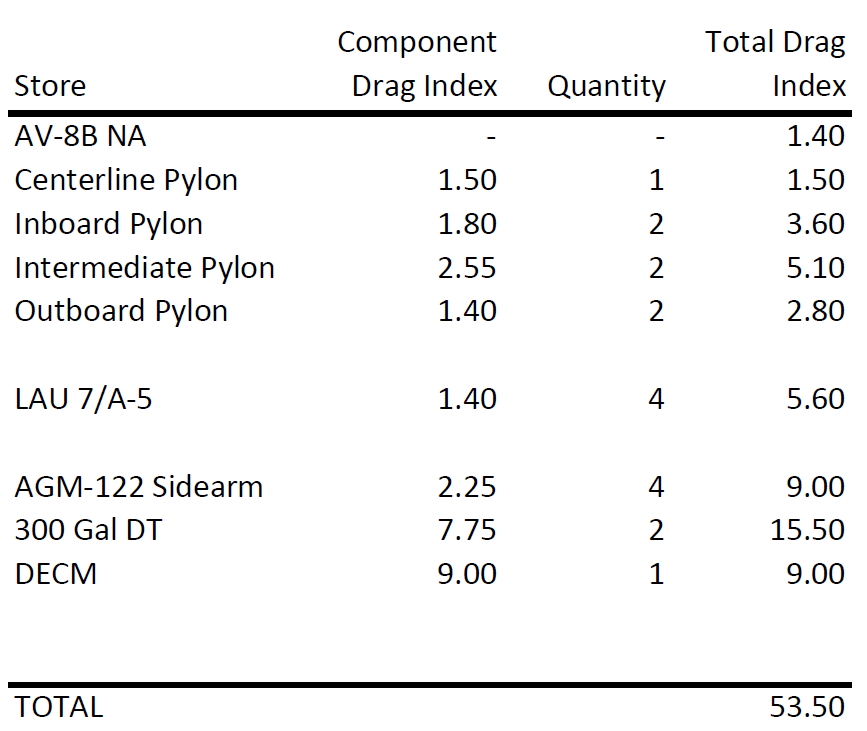
I have been continuing to think about this issue, and while I don't have access to my gaming machine at the moment, I did acquire the AFMs for the AV8. Strangely, I can't seem to find a practice problem that shows how to work out the drag index, so I'm not sure if I am calculating correctly. I'll attach my work for Capt Orso's load out though, would any of the SMEs here be able to tell me where I need to make changes? I am arriving at a DI of 53.5. The constant mach cruise charts for an AV8 using the -408 engine show that a .80 mach cruise in the original situation posed is possible, but no charts are published for a faster mach. The low altitude cruise series of charts only go up to 12,000 feet. According to these charts, given an ISA day and the load out proposed, the aircraft should be able to reach 420 KCAS but not be able to achieve 450 KCAS at 12,000 feet. (this is assuming a gross weight of ~24000 lbs, which I what I think Capt Orso's aircraft should weigh, but as I said I don't have access to my machine to check with DCS). Sources A1-AV8BB-NFM-000 15 Sept 2001 A1-AV8BB-NFM-400 1 Feb 2003

-
I kinda doubt this. In the case of the speed brakes hydraulic pressure is not used to hold the control surface in place. The control valve moves on command from the speed brake switch, directing hydraulic pressure to open or close the brake as required. When the switch is neutralized, so is the valve. The hydraulic fluid downstream of the valve holds the brake in place, since one of the greatest advantages of hydraulically operated systems is that the fluid (MIL-H-5606/83282 in this case) is incompressible. Hydraulic components drooping overnight have nothing to do with hydraulic pressure bleeding down, but rather with wear over time in the valves allowing hydraulic fluid to leak by. If the speed brakes opened simply because the hydraulic pressure bleeds down, they would start to open shortly after the engines are shut down, since hydraulic pressure drops almost immediately in that case. (I will admit that the -1's diagrams on the hydraulic system are a little weak, so if anyone has a maintenance manual that contradicts any of my statements I would really like to see it. That isn't sarcasm, I actually really enjoy systems study). We arrive at the cold airplane in DCS with the brakes open, just like in RL, because TO 1F-5E-1 directs the pilot to extend the speed brakes in the after landing checklist.
-
In addition to Herby's comments regarding IAS v TAS, I would also point out that saying you are using lower engine output at lower altitudes might not be correct; what I mean is that the engine at 100% RPM at 16k is producing much less thrust than the engine at SL at 100%. Aerodynamics for Naval Aviators shows that a fixed geometry turbojet will be capable of producing 67 percent of it's sea level, ISA rated thrust at 16,000 feet. Obviously this wouldn't be an exact representation of the Pegasus engine, but the concept is the same. Air density decreases exponentially with altitude (recall that ~ half of the earth's atmospheric mass is at FL180 and below) so as soon as you start climbing, you are losing available thrust on a similar exponential curve. All that said, I don't have the Harrier NATOPS (yet) but hitting .83 mach on an aircraft with a .90 redline while hauling 4 missiles and a pair of tanks in the teens sounds reasonable to me. I could certainly be mistaken there though, I would be interested to crawl into the books on it.
-
One common training tool for the in flight relight decision is to look for the 3 F’s - Fire, FOD, or Frozen spool(s). If one of those occurred (battle damage counts as FOD, bird strikes being a common consideration also) it may be best to secure the engine and RTB. Also, with all respect to Charly_Owl, I would be very surprised if the extinguishing agent is a foam. Every jet I am familiar with uses a Halon type gas for extinguishing. The -10 for the A10A doesn’t appear to specify- can any of the A10 SMEs with RL experience shed some light here with regards to the specific agent?
-
Working great here now Alpenwolf, instantly visible. Thanks! Hard pass. I had to really crawl into Discord while the Cold War server was down as I was flying on a server that leans heavily on it, and it is a dumpster fire of flaming, off topic conversations, negativity, and moderators having to repeat the same announcements over and over because people are too lazy to read. (And that isn't a knock at all on the sever, their excellent team of creators, or most of the pilots, just on the kind of conduct that an environment like Discord seems to bring out from people). SRS invites its users to an increase of systems knowledge in their chosen aircraft (what frequency bands can I access, what aircraft systems need to be operational for the radio(s) to work, where are the radios located physically in the cockpit and how do I key up?) and communication discipline. DCS strives for realism and SRS is currently an amazing community development that fosters and encourages it. I'm a little short on sympathy for people who are too lazy to embrace such a wonderful tool as SRS (and I'm not directing that at all to anyone contributing to the discussion here), which has been provided to us for free and has a tiny system footprint. I don't want to step backwards in realism for comms, nor do a I think a further split in the comms base is wise. As for the information distribution uses of Discord, Alpenwolf has always been very connected to the community through this thread (and the thread that came before it). It is my opinion the more measured pace of a forum and the ability to more easily compose full paragraphs, link to various sources, ect elevates the discussion, where Discord seems to devolve into SMS style spats.
-
Good point spiddx. Nothing to stop you from sliding a full drop tank down the runway during takeoff roll if you aren't careful what you touch though.
-
I tried again to get on this morning so I will share my results for your troubleshooting Alpenwolf... -launched DCS, couldn't see server, no direct IP connection -tried a PING command using the DOS command window. I was able to ping your server -launched DCS again, still couldn't see your server, no direct IP -closed DCS, launched SRS, joined your SRS with no issue -launched DCS, voila, your server was there in the browser -closed DCS, closed SRS, relaunched DCS only and your server was still right there in the browser This is such a strange issue, hopefully these notes can help as you try to track it down.
-
Darcwaynard is correct, the jettison system is tied to a hot battery bus and has no interface with the WoW (weight on wheels) system. You don't even need to have the battery switch ON to use either the selective jettison or the emer system. That is why the emer jettison has a plastic cover and the select jettison switch is the type that requires you to pull to move it from center.