BravoYankee4
-
Posts
625 -
Joined
-
Last visited
Content Type
Profiles
Forums
Events
Everything posted by BravoYankee4
-
Very interesting approach. However I have never seen any on-off-on switches with the contacts split over upper and lower set when in the middle position. Not saying that there aren't any, just that the ones I have is either up or down in the connections.
-
The easiest approach (perhaps not the best) would be to do a map of northern Sweden, Norway, Finland and Russia. Less to model (since there isn't that much of infrastructure etc.) but still open for a lot of different scenarios including NATO.
-

Cockpit temperature indication/effects?
BravoYankee4 replied to Flamin_Squirrel's topic in DCS Core Wish List
Aha, we need a cockpit temperature variable in the export.lua so we can control room heating/cooling through DCS-BIOS :) -
There was a lot of parking and maintenance areas along the road 184 (Lidköping - Skara) mainly in the Hasslösa - Vinninga surroundings. All are gone now, but if you know what to look for you can see some of them. Don't remember if that road was ever used for takeoff or landing?
-
That rear section of the KB pod was initially intended for additional electronics, however that never happend. So that unused space was then redesigned to house the flares. So that is how it became a combined chaff and flare pod :)
-
And F 16 was a fighter wing that only had JA's as far as I can see - which also cements that theory of it being used on the fighter version.
-
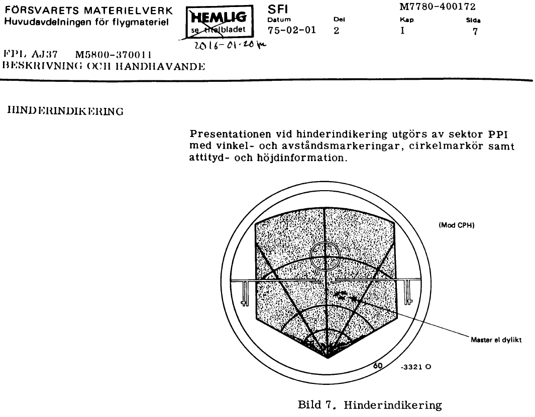
Here’s an example from the manual about the radar obstacle indication. In the picture example it is referred to as antenna towers (or similar).

-
Speaking of weight. The chaffs where originally made of silvered nylon strings and later on it was aluminized fiberglass strings. During the initial tests there was some complaints from nearby farmers about having “aluminum waste” at their land and posing a threat to their animals. There was an agreement that any animal deaths caused by this would be compensated for. None where claimed. Later on there was some official studies by the government veterinary service conducted, feeding cows and goats with the fiberglass strings. The result was that there was no harm caused to the animals by this nutritious supplement ;)
-
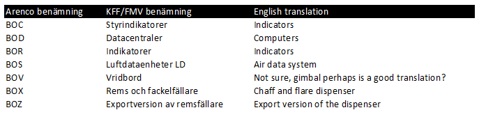
Yes, I found some information about that the abbreviations was a result of the military deliveries within the Arenco company needed to be kept secret. [ame]http://www.fht.nu/Dokument/Flygvapnet/forsv_elektro/Arenco/arenco_140811.pdf[/ame]
-
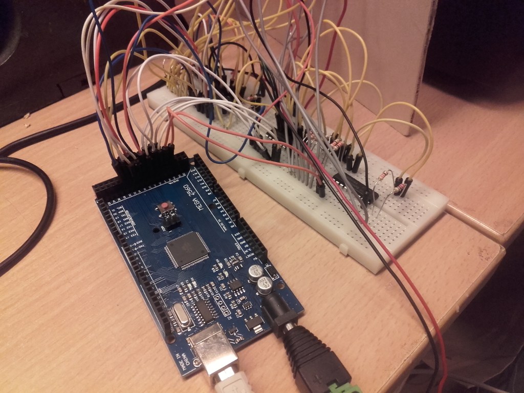
Interesting approach. Personally I'm going for a modular system having several small specialized boards. I.e one board for communication (Rs-485 interface and arduino), one board for inputs (breakout board with terminals), one board for outputs (breakout board with ULN2803 and terminals) and one board (shield for the arduino MEGA with RS-485 interaces).
-
Here is an english page about the Viggen with a pretty good summary of all variants. http://craymond.no-ip.info/awk/avvig.html
-
Hm, that pod referred to in that Italian page says 325 kg, but in the SFI document it says a total weight of 255 kg. I also found this document (yet another one in Swedish) that is really interesting - however not adding any details about the chaff amount. [ame]http://www.vikingroost.org/pdf/MMrapport__utg_2.pdf[/ame]
-
Yes, I have seen several references to a radar reflector at one of the Öland lighthouses that was used frequently for updating the navigation system (before going out over the Baltic sea).
-
The outer pylons (Robotbalk R7V och R7H)was originally hardwired for the RB 28 missile, and it wasn't until the AJS upgrade they could be used. So not just the new weapons, also the the load out capacity changed.
-
In top, it is a standard oh-film printed with a laser printer. Then I have a semi transparent film* on a plexi glass sheet. My initial plan was to use standard stage lighting color sheets and low voltage light bulbs (to get the different colors), but for the proof of concept I am using LED's in different colors. The LED's are controlled by a Arduino MEGA via a couple ULN2803 drivers. * I Have a friend working at an advertiser company and I got this film from him. It can be printed, howver I don't have that kind of printer. It is made for this purpose (backlit commercial signs, panels). http://www.orafol.com/gp/europe/en/products/inkjet-printing-solvent-based-product-details/items/orajet-3850
-
We are using DCS-Bios. A great software that makes a connection between the DCS simulator and Arduino boards. It can be used for both input (analog potentiometers, switches and rotary controls) and output (led, servo). So with this you can build a complete cockpit with "real" hardware. The downside, just a few DCS modules are supported so far. Perhaps the community can step in and help adding more eventually (and let the developer focus on core functionality). [ame] [/ame]
-
There is one big mistake in your schematic - you have connected the wires to Normally Closed. It should be Normally Open. And best practices says that you connect GND to Common. Doesn't matter with this kind of switch, but if you have a two position switch and you need two inputs it does matter.
-
Gettho style annunciator panels for the MIG. It is a card board mockup with the purpose to try different backlighting techniques for future builds. Meanwhile it gives that extra touch flying the MIG
-
Am I the only one that is flying the MIG-21 with DCS-Bios and/or HawgTouch?
-
So here is the final countermeasure part with the KA pod. There are some comments in the end of the document about updated panels. So this information might not be 100% relevant for the AJS version we will get. But the basics will probably be the same, with some updated/improved features/functionality. Other might chime in about if this system is to be regarded as complex for its time or not, compared to other aircrafts in the same era. Electronic countermeasure pod.pdf
-
If you power the MEGA board with just the USB cable, you have a maximum total current of 500mA. Each I/O pin is rated for 20mA (but can handle a maximum of 40mA). You have 54 pins available, so it is a simple math. For this kind of application you probably don't need 20mA per LED. They are visible with less current than that. Note that each GND pin can sink maximum 200mA, but there are 4 of them. The output groups can only handle a maximum ammount of current too, so keep this in mind. Here is a good page about this: http://playground.arduino.cc/Main/ArduinoPinCurrentLimitations
-
An Arduino MEGA gives you a lot of outputs. However the maximum total current is limited, so you might need some external transistor/relay if you have a lot of lights. I'm using ULN2803 for this myself. For a greater number of inputs an outputs, read about the RS485 bus with slave nodes.
-
Here is the dispenser pod, KB. I will continue with KA (electronic countermeasure) tomorrow. Chaff and flare dispenser pod.pdf
-
Here is a translation of the part with the radar warner from the SFI document. I will continue with the countermeasure systems/pods some day, since they are overlapping in some parts. Radar warner.pdf
-
Perhaps not applicable to all military service... 4-3-23. Use of Aircraft Lights a. Aircraft position lights are required to be lighted on aircraft operated on the surface and in flight from sunset to sunrise. In addition, aircraft equipped with an anti-collision light system are required to operate that light system during all types of operations (day and night). However, during any adverse meteorological conditions, the pilot-in-command may determine that the anti-collision lights should be turned off when their light output would constitute a hazard to safety (14 CFR Section 91.209). Supplementary strobe lights should be turned off on the ground when they adversely affect ground personnel or other pilots, and in flight when there are adverse reflection from clouds. b. An aircraft anti-collision light system can use one or more rotating beacons and/or strobe lights, be colored either red or white, and have different (higher than minimum) intensities when compared to other aircraft. Many aircraft have both a rotating beacon and a strobe light system. c. The FAA has a voluntary pilot safety program, Operation Lights On, to enhance the see-and-avoid concept. Pilots are encouraged to turn on their landing lights during takeoff; i.e., either after takeoff clearance has been received or when beginning takeoff roll. Pilots are further encouraged to turn on their landing lights when operating below 10,000 feet, day or night, especially when operating within 10 miles of any airport, or in conditions of reduced visibility and in areas where flocks of birds may be expected, i.e., coastal areas, lake areas, around refuse dumps, etc. Although turning on aircraft lights does enhance the see-and-avoid concept, pilots should not become complacent about keeping a sharp lookout for other aircraft. Not all aircraft are equipped with lights and some pilots may not have their lights turned on. Aircraft manufacturer's recommendations for operation of landing lights and electrical systems should be observed. d. Prop and jet blast forces generated by large aircraft have overturned or damaged several smaller aircraft taxiing behind them. To avoid similar results, and in the interest of preventing upsets and injuries to ground personnel from such forces, the FAA recommends that air carriers and commercial operators turn on their rotating beacons anytime their aircraft engines are in operation. General aviation pilots using rotating beacon equipped aircraft are also encouraged to participate in this program which is designed to alert others to the potential hazard. Since this is a voluntary program, exercise caution and do not rely solely on the rotating beacon as an indication that aircraft engines are in operation. e. Prior to commencing taxi, it is recommended to turn on navigation, position, anticollision, and logo lights (if equipped). To signal intent to other pilots, consider turning on the taxi light when the aircraft is moving or intending to move on the ground, and turning it off when stopped or yielding to other ground traffic. Strobe lights should not be illuminated during taxi if they will adversely affect the vision of other pilots or ground personnel. f. At the discretion of the pilotincommand, all exterior lights should be illuminated when taxiing on or across any runway. This increases the conspicuousness of the aircraft to controllers and other pilots approaching to land, taxiing, or crossing the runway. Pilots should comply with any equipment operating limitations and consider the effects of landing and strobe lights on other aircraft in their vicinity. g. When entering the departure runway for takeoff or to “line up and wait,” all lights, except for landing lights, should be illuminated to make the aircraft conspicuous to ATC and other aircraft on approach. Landing lights should be turned on when takeoff clearance is received or when commencing takeoff roll at an airport without an operating control tower.