gyrovague
-
Posts
189 -
Joined
-
Last visited
Content Type
Profiles
Forums
Events
Everything posted by gyrovague
-
 The weapon selector on the F-14 stick has the top position as "SP/PH", and the weapon selector press action toggles between those two missile types, so making "up" do it would not be realistic, as there is no further up position on the stick's weapon selector. I suppose if there is sufficient demand, we could add a special option to allow this, so that pressing "up" in the PH/SP position would emulate weapon selector press. (Edit: this feature has now been added) The weapon selector press action is not specific to PH/SP toggling, it has different functions in different positions of the weapon selector. In SP/PH position, it toggles between those missiles. In sidewinder position, it steps missiles (i.e. selects which one will be fired (and therefore also which one provides IR seeker tone to cockpit audio). Between off and gun it needs to be pressed (on the real stick, and VKB (and perhaps Virpil) F-14 grips) to move between those positions because of a physical detent preventing it from being moved otherwise.
 -
DCS crash during loading mission with F-14B
gyrovague replied to Razorback's topic in Bugs and Problems
The backtrace indicates something to do with simshaker. edit: not sure that's the cause of the crash however, probably not -
"PRESET" and :GUARD" ARC 159 Pilot Controls Switched
gyrovague replied to Bearfoot's topic in Bugs and Problems
Thanks for the posts, fixed internally (fix for the first post automatically fixed the second post too). -
Is this F-14 specific, or does it happen in other aircraft too?
-
[NO BUG] Removing ANY pylon removes ALL
gyrovague replied to Bestandskraft's topic in Bugs and Problems
Some of these things are by design, for example the front rails (3&6) are fitted in a pair or not at all, and the rear rails (4&5) are also a pair AND require the front rails to be fitted (i.e. rear rails cannot be fitted without the front ones, due to AIM-54 cooling IIRC). If you remove either 3 or 6 pylons(rails), it will clear 3,4,5,6. If you remove either 4 or 5, it will clear both 4 and 5. That said, there are certainly known shortcomings/issues in our implementation of the multitude of loadout combinations, and unfortunately many of these issues have no known fix right now. -
[RESOLVED] MK-20 Rockeye loadout, max 8, not 10.
gyrovague replied to Looney's topic in Bugs and Problems
This has been addressed internally now, so should hit openbeta in a few weeks. -
It should only switch to TWS-A if it was in TWS-M when a phoenix is launched. It should not switch to TWS-A when launching phoenix in STT, or BRSIT or PH ACT.
-
This is the thing that is fixed now, and sounds like nearblind and klarsnow are referring to this too.
-
This should be fixed now.
-
Spent a bunch of time investigating this the past few days, there appear to be a number of reasons causing this, and some of them are legitimate: 1) targets with large acceleration vectors - legitimate, since TWS in the tomcat only tracked position and velocity according to our info. Large acceleration changes of course lead to velocity changes over time, and if this falls outside the threshold of track correlation, it will form new tracks. Turning sharply is an example of a large acceleration change (rate of change of velocity vector). 2) rubberbanding in MP - legitimate-ish, the radar sees the target going backwards and forwards, so forms new tracks since the observations don't correlate to track extrapolations, shrug... Not sure we can solve this while still maintaining realistic TWS tracking, and not just directly using DCS object info. 3) closely spaced targets just flying constantly straight and level - bug/shortcoming I've fixed/improved the behaviour regarding #3 at least. It can still occur somewhat, as it happens at the boundaries between where clustered targets split or combine, but the effects should be far less now (no sudden massive velocities peeling off at large angles).
-
The TWS algorithm only tracks position and velocity (as change in position over time), and only dead-reckons based on that too. Acceleration is not calculated, tracked or (obviously therefore) used in any calculations, so any target with large acceleration vector (e.g. due to tight turns etc.) can cause a mis-correlation with a previous track and establish a new track. Taken together with TWS only getting observations on a target every 2s, one can see how rapidly maneuvering targets cannot be tracked. Some of the observations posted do look suspect however, but I also think there could be other factors involved in some of the cases, such as MP rubberbanding (if the position of the object jumps forwards and backwards, you imagine what that does to the calculated velocity vector).
-
I think that is one of the issues that was fixed while implementing TWS-A, so it should be better for TWS-M too. Let us know how it goes!
-
[BUG] Visual fix not working as described in manual
gyrovague replied to Bestandskraft's topic in Bugs and Problems
Fixed internally, thanks for the report. -
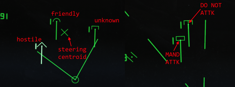
Well spotted :detective: We replaced the GND MAP button above DO NOT ATTK with MAND ATTK. Those labels changed quite a bit across F-14 blocks over the years. IRL the GND MAP feature changed radar to a shorter pulse length (IIRC) and some other presets, we haven't used that button anyway.
-
As long as you see it on own radar, it doesn't matter whether you were guided there by datalink or some other reason.
-
Track While Scan - Auto As most know, we had a TWS-Auto implementation for the F-14 at launch, but it was quite unreliable and ended up causing more trouble than it was worth, so it was disabled. After launch of course we were kept quite busy, and it was some time before we managed to revisit and eventually rewrite the TWS-Auto system. We’re finally ready to re-release it now, and this post will summarize the functionality. As you may remember, both TWS modes require the scan frame to be 2 seconds, and only support 2-bar ±40° or 4-bar ±20° scan volume modes (the radar gimbal moves at 80°/s, so you can see where the 2 second frame comes from in these two scan volume options). Very simply put, TWS-Auto attempts to keep the TWS pattern pointing where it is most useful in azimuth and elevation, while also controlling the optimum scan volume. TWS (and all the PD radar modes in F-14) uses ground stabilized (a.k.a. Earth fixed) patterns, so the azimuth and elevation angles are relative to a tangential plane on the surface of the earth at your present position, with azimuth further being relative to the F-14 longitudinal axis too (i.e. 0° is directly ahead on the imaginary plane, -20° is to the left, etc.). Function of centroid The azimuth and elevation angles are determined by a weighted centroid of targets in the scan volume. What this means is that some targets contribute more to the centroid than others, depending on a few factors outlined below. Essentially the position of each target is multiplied by its weight factor divided by the total weight of all targets, and these weighted positions are added together to give a centroid. Only sensor targets (i.e. own radar) are considered, not datalink targets. Two separate (but somewhat related) centroids are calculated as part of the TWS-Auto update procedure: a steering centroid, and an illumination centroid. The former facilitates steering cues (on HUD, VDI, TID, DDD) to help the pilot maintain optimum target coverage, and also displays a small X on the TID indicating the steering centroid position. The illumination centroid controls the azimuth and elevation of the scan pattern center by using the angles from the aircraft to the computed illumination centroid (in TWS-Manual, these are directly controlled by the radar azimuth and elevation knobs on the RIO sensor control panel). The velocities (change in position over time) of both centroids are also calculated, used to calculate steering, and dead reckoning for a short period when all targets are lost (in an attempt to re-acquire them at their expected positions). Weighting targets As mentioned, a few factors influence target weighting. These differ slightly between the calculations for the steering centroid and the illumination centroid, but largely consist of the presence of a launch zone (targets marked as friendly by RIO will never get a launch zone), whether a missile is already underway to a target, and some RIO selections on targets such as DO NOT ATTK (disregards from weights completely, shows a small vertical bar over a target) and MAND ATTK (forces evaluation and raises importance, only one target may be selected for this, and mutually exclusive with DO NOT ATTK. Shows a small horizontal bar over a target). Targets that are not displayed on the TID screen in the currently selected TID mode and range are also disregarded completely. In addition, targets which are deemed to be leaving the scannable volume are also raised in importance, if they are already deemed important by the previous criteria. For the steering centroid, the radar gimbal limits (maximum extents, basically ±65° in both azimuth and elevation) are considered, while for the illumination centroid, the current scan volume limits are considered (i.e. either 2-bar ±40° or 4-bar ±20°). This causes the illumination centroid to adjust towards important targets leaving the current pattern, and allows the steering centroid to shift towards targets that are leaving the maximum radar gimbal limits (i.e. pilot would need to steer towards that to keep them illuminated). Engaging TWS-Auto When TWS-Auto is first engaged, there is a period of 8 seconds where the manual controls for azimuth, elevation and the scan volume pattern are still in effect and can still be controlled by the RIO. After this period, the computer takes over. The scan volume pattern (2-bar vs 4-bar) is re-evaluated every 4 seconds, while the centroids are re-evaluated multiple times per second. The weights are updated at the end of each 2 second scan frame. The scan volume algorithm considers the future positions of all targets, and selects between which of the two options would give a greater total illumination weight. If they are equal, 4-bar ±20° is selected. Firing an AIM-54 Phoenix while in TWS-Manual will result in automatic selection of TWS-Auto. Furthermore, when any AIM-54 missiles are deemed to still be in flight (up to 16s beyond their expected time to impact), TWS-Manual cannot be entered (the button press is ignored). Target tracks that have a missile launched at them will also behave as if Track Hold (the button to the left of the TID fishbowl) has been selected, i.e. they will continue to be extrapolated for up to 2 minutes if their radar contact is lost. Symbology The steering cues on HUD, VDI, TID and DDD will direct the pilot horizontally only, based on the steering centroid. By default, lead collision steering is employed. If the RIO uses the CLSN button next to the TID fishbowl, pure collision steering is instead calculated. Since both the pilot and RIO can see steering cues on their respective displays, coordination of required maneuvering is made easier. The steering cue on HUD and VDI is an upside-down T (hence called a steering tee), while on the TID and DDD the steering cue is a small square. These four displays have different steering sensitivities: TID is 40°/inch, DDD is 128.5°/inch, VDI is 25°/inch and HUD is 26.5°/inch. In conclusion TWS-Auto can be a handy tool for maintaining illumination on targets under attack, even while maneuvering about 60° away from the direct path to the targets. However, as pointed out by one of our RIO SMEs, good RIOs did not make exclusive use of TWS-Auto while hunting for new contacts, as it limits your overall situational awareness. RWS is still useful for scanning huge volumes, and TWS-M is still useful while maintaining the ability to control the scan volume angles. The Track Hold function (button to the left of the TID fishbowl) is also quite important, to maintain tracking (by extrapolation) on targets that would otherwise be lost in the PD filters. Take a first look at TWS-A together with Jabbers here:

-
To be clear, the guesswork wouldn't be around how JAM/JET etc. is displayed on DDD and TID, we have good information on that (and even, interestingly, how said jamming strobes can be shared over datalink and used to triangulate a jamming source position). It's more about how to convert a boolean jamming value (the only info provided by DCS for a jamming source) from any particular aircraft into something resembling received jammer power. One could also argue that it would be unfair to apply some one-size-fits-all thumbsuck jammer power formula to all jamming aircraft, since they can have very different jamming capabilities, potentially independent of physical size even, e.g. say EA-6B compared to A-6E for example, or EA-18G compared to F/A-18F etc., but going down the rabbit hole of us trying to maintain some internal database of what fake jammer power to use for each jamming aircraft also becomes a bit ridiculous (given that AFAIK DCS itself does not model this in any way). We'll come up with something, but it just will most likely stray much further from reality than anything else in our simulation, unfortunately.
-
We can do something, but it will be venturing into very speculative territory, which is not ideal for us. Concepts like jammer strength, type, directionality etc. don't exist in DCS, and of course ECM and ECCM etc. systems are highly classified. Jamming in DCS is basically an on/off thing, so anything on receiver side (the jammee, if you will) is totally made up, in terms of how much and what type of jamming it is perceiving, and whether or not its own radar can "burn through" etc.
-
No, this was part of why the TWS-a was so delayed, we had to unentangle all the phoenix changes from the TWS-A changes, because the phoenix changes ended up not working correctly in multiplayer due to factors completely out of our control. We don't know when we'll be able to re-introduce the phoenix fixes again.
-
Do you have current openbeta? The vJoy bypass thing has already been in there for a few weeks. We did not realize some sticks (like Brunner) actually make use of FFB via vJoy, so it sounds like we may need to reconsider this then. Part of the problem is that DCS gives no correlation between input devices and FFB, so the presence of any FFB device (including vJoy) registers as it having FFB, and the APIs to set FFB have no concept of which device to apply it to. However, if you merely have vJoy installed for other purposes (combining axes, or doing various other special functions), it was causing F-14 to try to apply FFB for trim, which only works if you have an actual real FFB stick for the input device. The simplest fix is probably just for us to remove the vJoy automatic bypass altogether, and let the user control FFB fully via the special option we already have in there.
-
Yes, the DDD (and TID) visualizations for these are on our list, just pretty low priority, especially since jamming itself is so rudimentary in DCS (understandably so, since these things are very highly classified). It should get added in the coming months as we head towards exiting EA.
-
Data Link Not Showing AWACS data beyond 150 miles
gyrovague replied to Banzaiib's topic in Bugs and Problems
Thanks for the report, it is on our list to revisit F-14 datalink once more pressing tasks have been completed. The AWACS APIs in DCS have changed a few times since F-14 release, we're awaiting some info from ED on the latest correct way to now receive contacts. It seems as though we may need to implement a link16 receiver now, which is of course not true to real life, but we'll see, maybe ED can give us another way. F-14 should currently receive all contacts that are up to 250NM from AWACS, as long as they're within line-of-sight (not occluded by terrain or horizon etc.), so not sure why you were seeing only 150NM on your side, but maybe MP somehow affects this too. -
[WIP] IFF wheels must be in octal / not decimal
gyrovague replied to tacno's topic in Bugs and Problems
Fixed now, in preparation for SRS pull request for transponder support. -
[RESOLVED] Radar track files never age out i
gyrovague replied to Santi871's topic in Bugs and Problems
I've not been able to reproduce this... There was a bug like this which was fixed in October 2019 already. Date: Fri Oct 11 17:29:57 2019 +0200 Fix untracked contacts in TWS not timing out (must form track within two scan frame times). Fixes #655 -
There is still no Sparrowhawk HUD planned.