Mortisrose
-
Posts
160 -
Joined
-
Last visited
Content Type
Profiles
Forums
Events
Everything posted by Mortisrose
-
Not using VR but I've been having consistently lower fps in multiplayer in comparison to the other MiGs. On the ramp cold start no radar on, I'll get ~30 in the MiG-19, ~40 fps in the 21, and 50+ in the MiG-15.
-
Not sure when this changed but there is now a smoke trail when the afterburner is on the same smoke as mill power.
-
Yes and many if not most servers in my experience has it set to unrealistic default.
-
Yeah the behavior must have change recently. I don't understand why the unrealistic option is default and the realistic option has to be manually enabled. It seems backwards to me.
-
I just tested this in a SP mission with the realistic reticule option on - the pipper moves over target when I establish a radar lock then moves back to center when I get an IR tone.
-
Also noticed there is some light bleed on the radar mode push-button around the red lights. It can be seen in the picture in first post. At night the lights did not have any light bleed.
-
The shapes folder failed integrity check on my end. I removed it from the hotfix and all works fine so far but I haven't checked it using VR yet.
-
There's bits of information all over the place, try googling '74hc165 mmjoy'. This topic was a lot of help for my build: https://simhq.com/forum/ubbthreads.php/topics/4362821/re-mmjoy-mmjoy2-build-your-own-usb-controller My throttle project thread has two examples of homemade 74hc165 shift register boards: https://forums.eagle.ru/showthread.php?t=231145
-
Personally I would use shift registers for that many switches and leave the encoders connected to a button matrix. Button matrices can get very messy when connecting over a dozen or so switches.
-
When loaded with four sidewinders the lower rails are untextured:

-
I'd say around 6-10PM GMT, server had 20 or so players around now last two days.
-
In the briefing for Persian Gulf mission the freq is listed as if I remember correctly 215mhz not 251mhz, Viggen pilots were asking if AWACS was down.
-
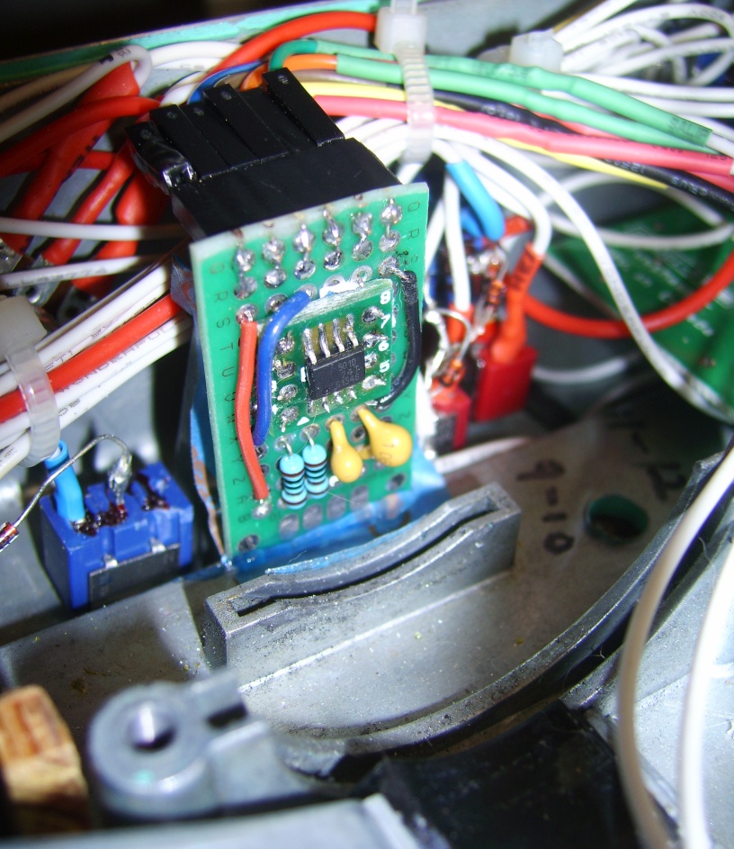
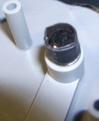
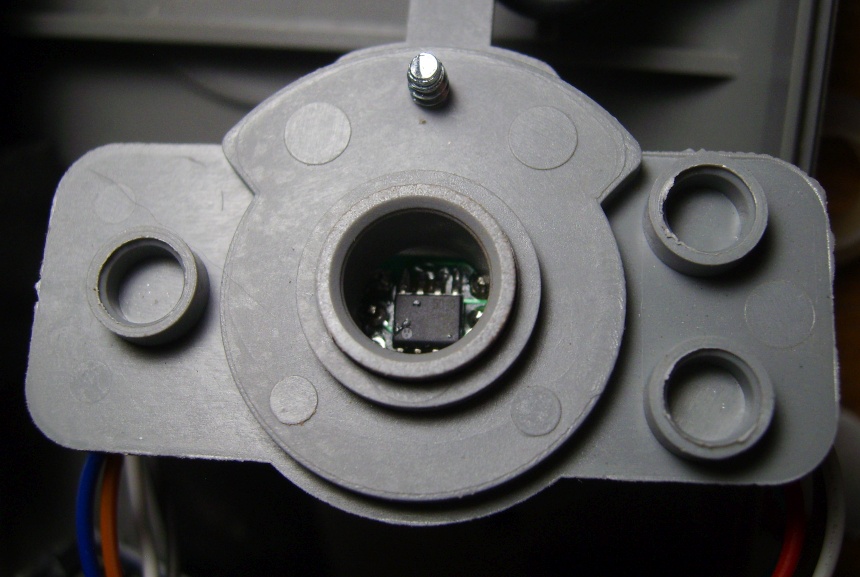
Thanks. I never could get those hall sensors to work, the TLE5010 work the first time I plugged it in. So far no misalignment after kicking rudder around for half an hour flying the P-51, maybe the setup needed some settling time. If it does continue to drift I'll try heating the inner layer of heat shrink to tighten around the magnet or maybe a bit of hot glue to the magnet as there is potential for movement in the space between the magnet and heat shrink. The force between the screw and magnet was so strong I kept it as it was just sitting on top. Goal in this project is to keep it simple with minimal destructive methods of modification. Picture below of the lever/magnet setup. The lock washer just underneath the shrink wrap is visible, this helps reduce play and the heat shrink is placed tightly over the top of screw head and snugly placed in the pot shaft opening further reducing play. There's also some magnetic force holding up the lever up from the base between the magnet and the wires/header pins on top.
-
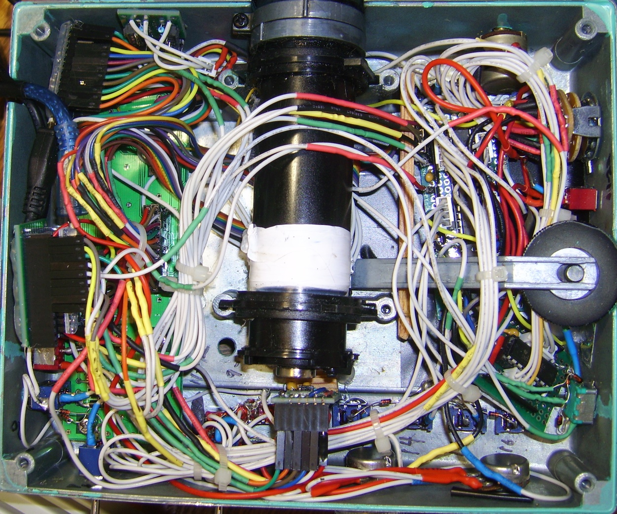
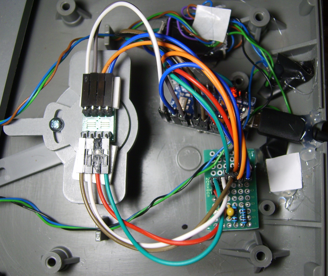
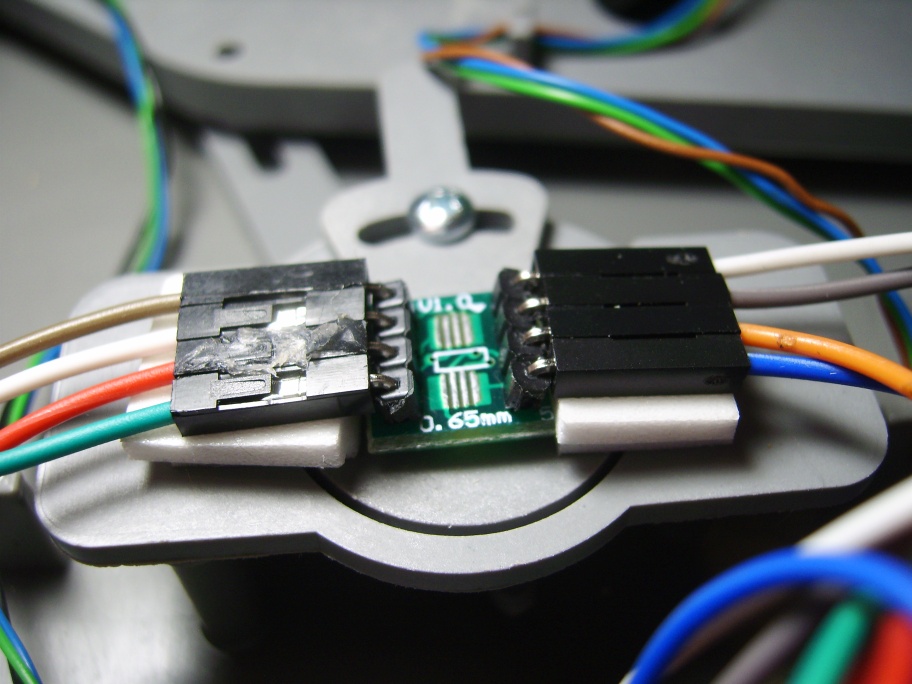
This mod changes out the old 8-bit controller and replaces it with an Arduino Pro-Micro w/MMjoy2 firmware and replaces the rudder potentiometer for a TLE5010 magnetoresistive sensor. The foot brake pots now have 10-bit res. and the rudder is set to 12-bit resolution. I had an extra TLE5010 already attached to an adapter from my throttle project and a partially completed circuit board and incorporated both into the project. After disassembly of the pedals the rudder pot was removed and a screw with washer was screwed tightly into the opening of the rudder linkage lever that housed the pot shaft. A small diametric Neodymium magnet was placed over the screw head and two pieces of heat shrink tubing was placed over the top of the screw and magnet to reduce the play within the rudder pot mount. The TLE5010 sensor adapter pins were then bent 90 degrees to the sides to lower profile, wires connected to adapter and two layers of mounting tape attached to the underside of the headers. The adapter/sensor was then attached to the top of potentiometer housing directly over the opening and then the housing placed over lever. Works good so far, thought I've noticed some drift with the min. center and max values, also I was unable to get auto calibration to work correctly and had to use manual calibrated settings.
-
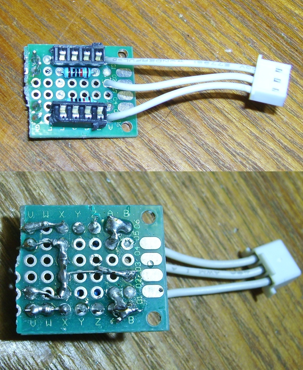
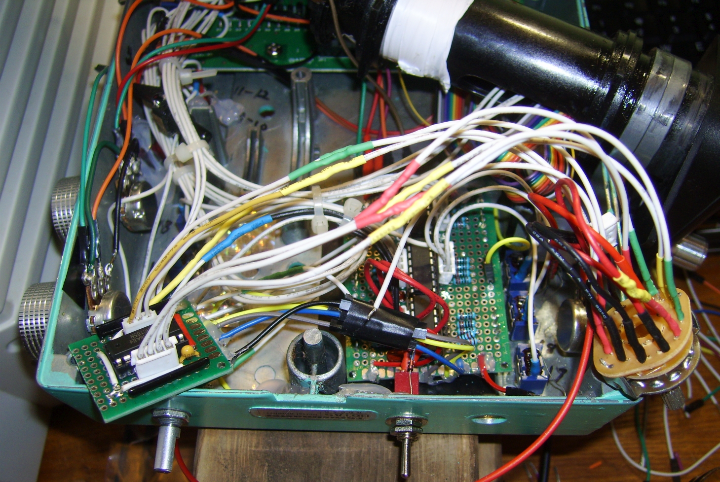
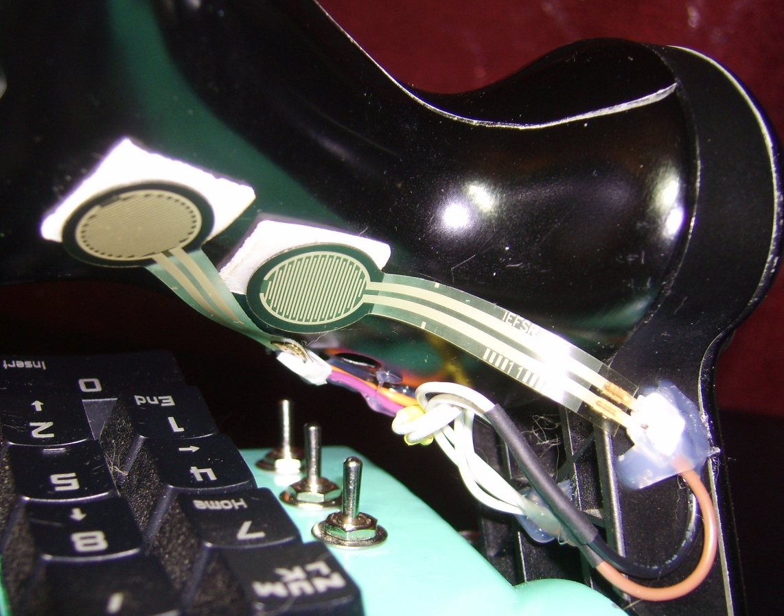
Design and construction of TLE5010 adapter and circuit board: The TLE5010 is a surface mounted chip so an adapter was used to attach to the perfboard. The adapter was mounted on top with a piece of paper sandwiched in-between to prevent short circuits since both sides of adapter contain circuits and solder points. Installation: The metal potentiometer bracket had to be cut back to fit the sensor module and diametric magnet. A piece of wood was wedged in the space between the throttle end bracket and sensor, hot glued in place and sensor wires zip-tied to hold the top. Works so far but a better installation method may be needed if it comes loose. Throttle base interior after 3rd rebuild: The Arduino Leonardo was replace with a smaller pro-micro, potentiometer wires all replaced around case, a dual pot from an old radio was installed, force sensing resistor circuit board connected to original throttle potentiometer connector, a strip of wood placed to hold the shift register board back for the throttle cylinder, and switch diodes all connected together with ground wires instead of directly to case interior.
-
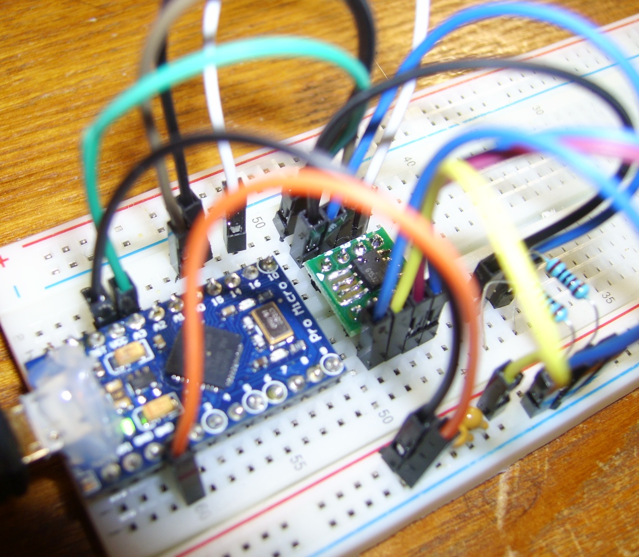
Can shift registers and and a TLE5010 sensor be daisy chained? I cannot get them to work together; the sensor stops working when the shift register board's MISO is connected with sensor. The board and sensor each have a CS pin.
-
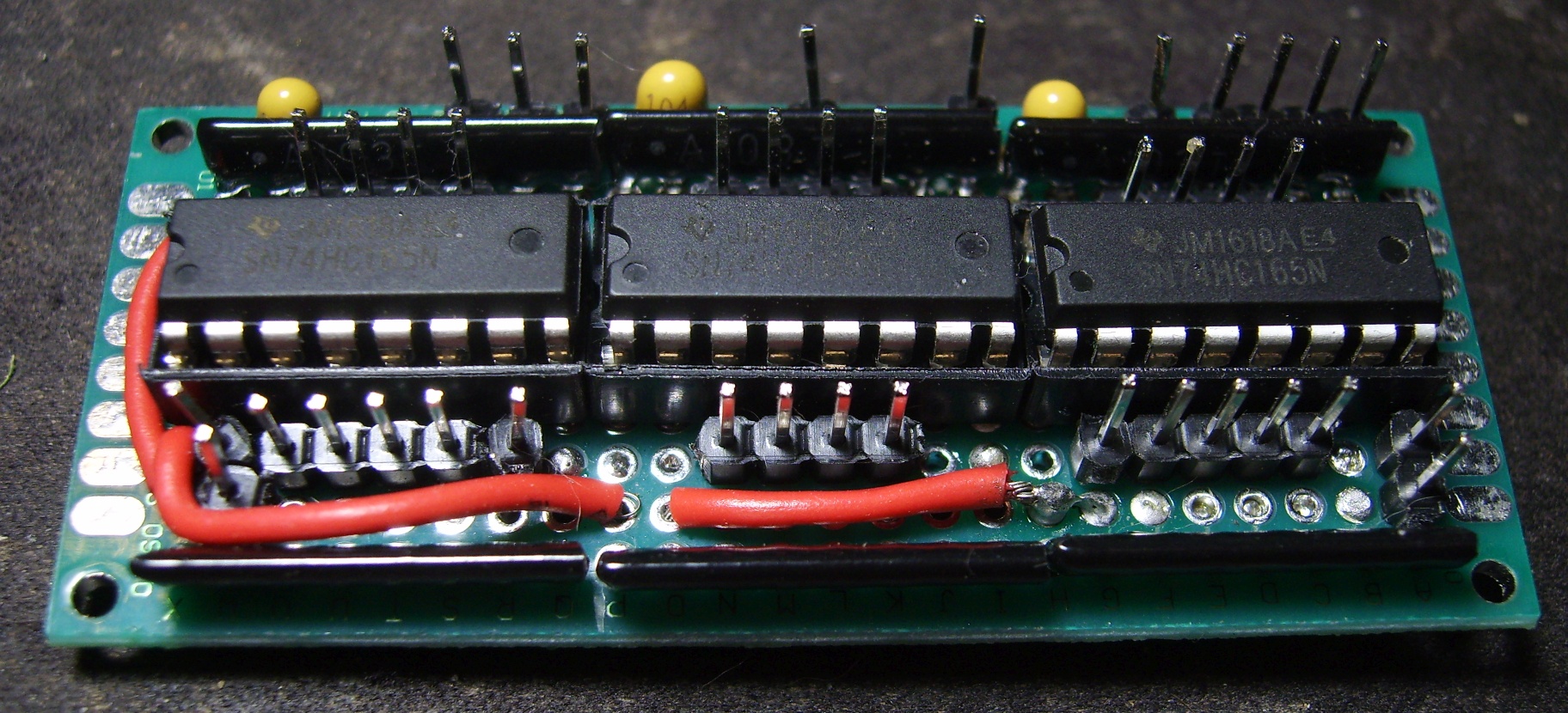
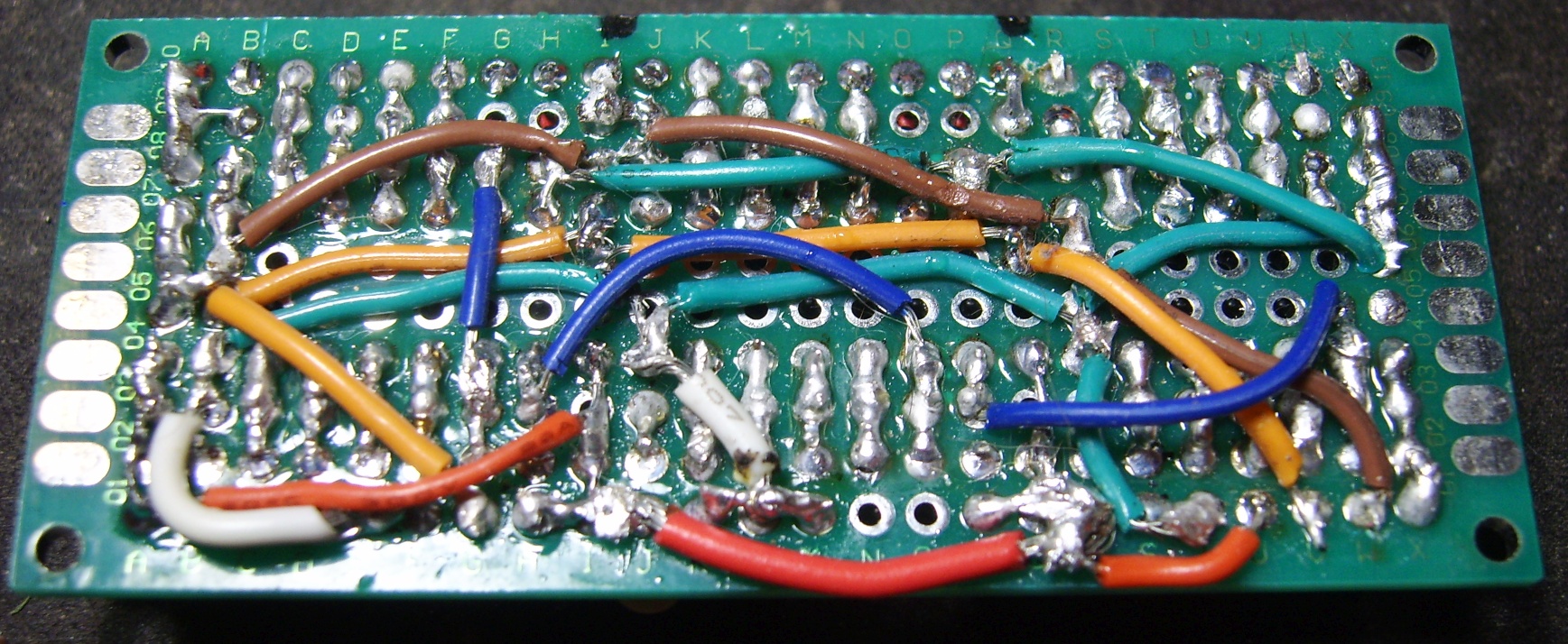
Work resumes again on the Cougar Throttle this time the shift register board was rebuilt for a new more compact design. Extra 5v and ground pins were added and resistor arrays were used for compactness. Soldering went better this time around though still tedious. Tested and works great so far. Next step is replacement of the old throttle potentiometer with a TLE5010 magnetoresistive angle sensor. I tried to replace it earlier with a hall sensor but couldn't get it to work correctly. So far this new sensor is working excellent in the test setup, it's very sensitive to magnetic fields and has good resolution.
-
Crashing on startup and yaw dampers completely glitched
Mortisrose replied to TheEmeraldSkills's topic in Bugs and Problems
I ran a repair and tried to reproduce the crash and so far no crash when using comms, so that may have fix it. Nope, crashed again -
The cougar throttle has a low resolution of 8-bits (256 values), the "generic" throttle probably has a higher resolution of 10 bits (1024) or more. I modded my throttle with a pro-micro and MMjoy2 firmware to make it 10-bit and standalone, from 8 to 10 bits it is noticeably smoother in output.
-
Crashing on startup and yaw dampers completely glitched
Mortisrose replied to TheEmeraldSkills's topic in Bugs and Problems
Couple days on the Growling Sidewinder server several other people and I had the same problem with CTD when trying to contact ground crew. It also crashed when I tried to contact AWACS, and I tried it by clicking on the screen. This started with the latest open beta patch. When I tried to contact ground crew in single player it did not crash. -
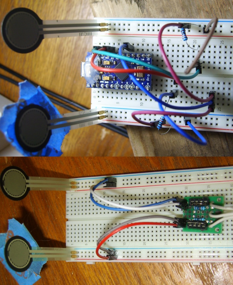
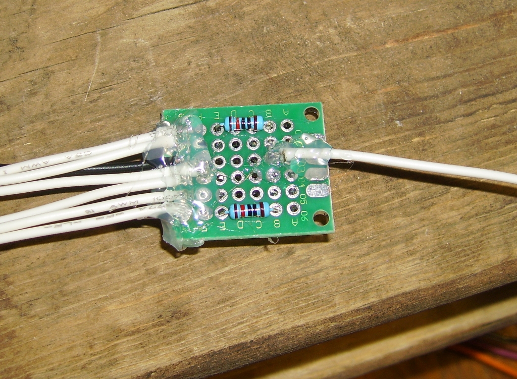
Force-sensing resistors now share an axis and work as I originally intended them to. In order to do that I had to take out the circuit board I made earlier and replace it with a newly built one. The design and testing: Sockets were installed so different resistors or a wire could be inserted and used to adjust the force needed to reach min and max value of the axis.
-
Looks like I've found the answer: https://sites.google.com/site/mmjoyproject/avto-pedali
-
Is there a way to combine two analog inputs to one assigned axis? I'm trying to combine my two force-sensing resistors so that the left one goes inverted from 50-0% when pressed and right 50-100% of the axial range when pressed. I tried the throttle double axis under spec. functions tab but it only works for one way left or right depending on setting, the adjacent input resistor stops functioning.
-
Added a fourth shift register for 7 rotary switch positions (left one position disconnected for an off state), added two force-sensing resistors under the throttle grip in attempt to replicate the function of the "rudder rocker" or "toggle rudder of X-45 HOTAS and TWCS throttle. Fourth shift register and circuit board (bottom left) Force-sensing resistor circuit board for the 10k resistors, 5v, ground and output wires. Force-sensing resistors mounted under grip with wires running down the inside of the grip support and into the base.
-
Same here, no gun sound internal or external, with or without gun sound mod.

.png.2e55d2cd8d8d4ef2bdd62aaf88d5cc8e.png)