
GumidekCZ
-
Posts
870 -
Joined
-
Last visited
Content Type
Profiles
Forums
Events
Everything posted by GumidekCZ
-
What ED and all 3rdparties should aim for is a best estimate RCS values across whole DCS sim. Problem is, that there is nothing anywhere written by ED, how did they come to these values. Did they tried co calculate its 3D models from frontal view with static RCS simulation analysis? I guess that not. Is it just base on guess made by some fighter pilot or the module developer guess? I don't know. What I know that if there is something suspicious about RCS difference, we can make simple analysis to back such claim. If my proof is not enough, than this can be done by someone from ED team, more educated (with good knowledge of composite properties, canopy material, coating), equipped with may be static RCS analysis software tool can make much more accurate result.
-
@Mike_Romeo this is not any proof of 3 sqm RCS for JF-17, this is just even less proof backed nice wish of to guys I didn't see anything from them , what might give us a hint, that they tell us the truth. @okopanjaI know that not all F-16 use the gold, the modern ones use other materials instead of gold. But we have the option in DCS to have the gold tint - so? On the other hand JF-17 is designed as a cheap fighter (when compared with its competitors) and from pictures present all the internet, not even Block 3 have black or gold tint of canopy glass - giving us clue of such feature used. If somebody want to have 3 sqm RCS, than they need for example post here any trustful document declaring use of such technology for Block 1, but according to photos, I still would be very sceptic.
-
@Mike_Romeo @AnarchyZG Seems you are very happy with RCS of JF like it is now, you making everything to stay it like it is by just trying to disproof any try to correct it. Good job guys, but first before you throw salt next time, try to gather evidence of your disprooval claim. Find better method if you can, or just leave the topic unresponded. Many thanks guys. @Mike_Romeo Not whole airframe is acting as Faradays cage. Every material other than metal (like ordinary plexy glass or composite nose cone) is just open hole to allow radar energy to go through and reflect from anythink behind it. @AnarchyZG Nobody is calculating just frontal area projection, really dont know where you get that. Why the hack you are waving here with F-22 RCS? This plane is absolute different class with astronomic price.
-
without F-16 HAVE GLASS, it would be just huge hole in airframe with so many reflective things inside/behind it. May be some day, Pakistani will also make one for its JF-17 fighter, if the technology used to made it, will be known to them. https://www.key.aero/article/have-glass-making-f-16-less-observable Another interesting cannopy and RCS info found here starting at page 16 (year 1979): https://aircraftdesignguide.com/wp-content/uploads/2020/03/10-Guidelines-for-the-Design-of-Aircraft-Windshield-Canopy-Systems-Chapter-Eight.pdf Please, if any of you want to write down here that JF-17 have to be smaller RCS just because its newer, more modern. Keep this in your mind for yourselves. Heards this many times before with none scientific support of such claim.

-
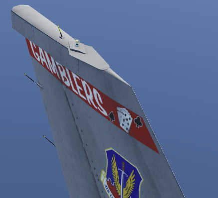
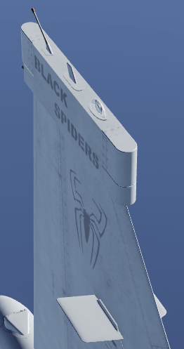
Nobody before me has introduced here more scientific method to compare RCS of two airframes, at least what I know. If you know about better one, you can show it to us. Didn't you read about the F-16 canopy Faraday cage RCS effect? Please try to Google it. Beside that, thick or thin line is a factor of sharp or round lead edge. F-16 has sharp to of tail avoinics compartment and JF-17 have round shade, more reflective. I really tried to be not biased to one airframe. I known that if I would be, this post would became just one big laugh to everyone. Materials used are same or very similar for both airframes. Nice to see & learn:
-
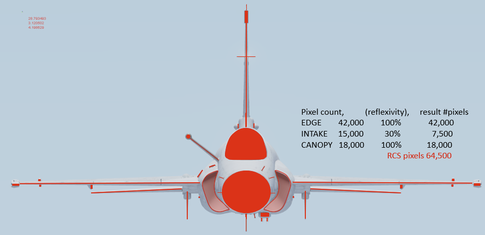
I have been long time suspitious that JF-17 RCS is to small when compared with other fighters. So I take a frontal pictures (DCS compares the frontal RCS, not any other aspect) from DCS model viewer of JF-17 and F-16C with same scale and draw a lines and areas of major reflection sources ( intake area, cockpit, leading edges, probes and sensors, wall behind radome). Than I added guessed reflectivity index in % to some special areas like GoldenF-16 cannopy with Faraday cage effect which reduces RCS, or JF-17 special intakes with same reduced RCS effect). Since DCS model viewer JF-17 is without pylons, I didnt count them. After that I took Zoner Photo studio, selected the pixels from both planes and count them. Result is little surprise to me, I thought that both planes would be very simillar, but this quick simple analysis showed, that JF-17 with all that stuff reflecting radar energy like the airframe wall behind the pilot head (no such thing behind F-16 pilot, just seat with golden plexy glass), the Jeffs RCS is even bigger than Falcons. So with this result in mind, the RCS of Jeff in DCS must have RCS = 4 NOT 3 as it is now. Both pictures are in scale! Once again EDGE pixels include not only any edges visible from front, but also Radome area. Canopy includes its airframe and cockpit back wall surface.
-
I want to report radar beeing able to detect targets inside of Doppler Filter speed gate (plus / minus 54 kts of my true speed). KLJ-7 relative_radial_velocity_min = 27,777777777778 m/s If closure rate with target is 545 kts na my true speed is 521 kts, everything in speed range +-54 knot of my true speed have to be filtered out, especialy against the ground. So with little math, notch will at this moment filter out anything inside of this speed range: 467 kts and 575 kts. As you can se from track, I was able to find my target and fire a missile on it inside of Doppler filter speed range. Shorty after launch the radar contact was lost, but still, above described error is bug worth of fixing. JF-17_detection_in_notch_BUG.trkTacview-20211204-223118-DCS.zip.acmi
-
YOU are ablsote True, "slap" ... bad Gumidek, Bad! Sorry for that! Correcting this now.
-
Bug I want to report here is about misalignment of IFLOLS – ICLS discussed in many topics here. Like this one: I searched for any evidence, how these systems were aligned in RW and surprisingly found these documents, where its described how certification process demanded to align and corelate these system to show almost exact/nearly same glideslope plane – not just angle, to provide pilot “seamless transition from ICLS needle guidance to IFLOLS visual guidance.” This was done through certification process of the systems described in documents down bellow. With this report, I want to mention, that we are still waiting for Eye-to-Hook height manual and automatic adjustment, corelated between these systems to allow to any plane in DCS equipped with hook to hit the deck with hook exactly between 2 and 3 wire or any other place decided manually by human controlled LSO station. Lack of this very important feature was also discussed many time on forum. I almost forgotten to mention here also the missing AN/SPN-46, AN/SPN-41 indication of landing aircraft radar lock on LSO screens for bad weather recoveries. F/A-18A-D Hornet Current and Future Utilization of Mode I Automatic Carrier Landings https://trace.tennessee.edu/cgi/viewcontent.cgi?referer=&httpsredir=1&article=1356&context=utk_gradthes Analysis of the Instrument Carrier Landing System Certification Process for Amphibious Assault Ships (page 24) https://trace.tennessee.edu/cgi/viewcontent.cgi?article=3528&context=utk_gradthes LANDING SIGNAL OFFICER REFERENCE MANUAL (handy document for Heatblure Forrestal class carrier) https://documents.pub/download/lso 4.2.2 Centerline Camera Stabilization And Crosshairs. There is mentioned that LSO PLAT cam was adjusted independently on ICLS and FLOLS by LSO before each recovery by aircraft Eye-to-Hook value. I dont know if the LSO PLAT cam is still adjusted independently at our Stennis class improved PALS system with new IFLOLS and whole new LSO station, when compared with the Forrestal class carrier. Nice feature to have is selectable Reticle illumination; black for day, white for night.
-
See the last 5 seconds before touch down and watch the "W" mark on HUD and AoA bracket. DCS Open beta 2.7.8.16140 and its ground effect bug, causing roughly 3 degree decrease in pitch. This nad behaviour is also present above carrier deck, causing unwated drop into wires with low AoA, many times graded by carrier LSO by "Landed on all three wheels" aka "3PTS-IW".
-
What is the angle of the vortex cone behind end of each wingtip. I personaly think, that the angle is to large and you have to fight this if in wingmen position, even if you have pretty large lateral spacing off the leads wingtip. Because the actual cone angle is more than 40°. Can any real pilot witness here, if in parade formation F-16/F-18 they need to compensate the leads vortex?
-
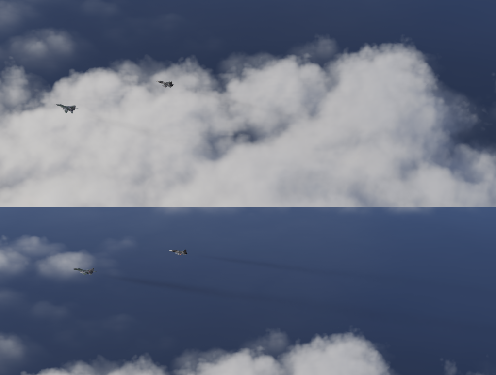
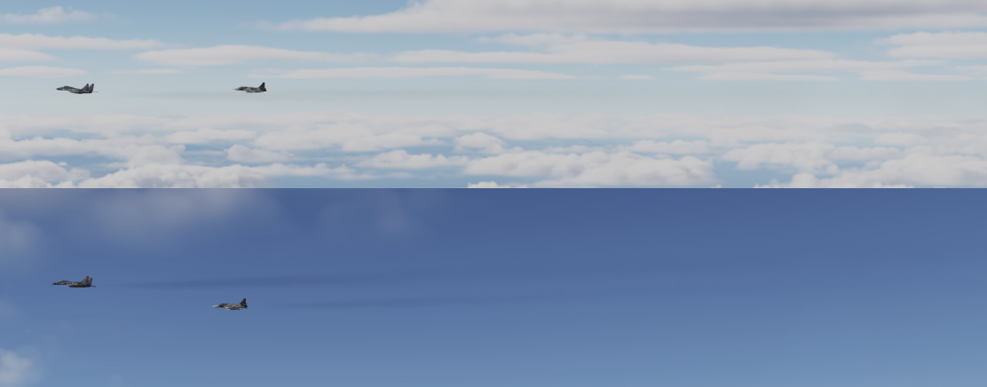
 DCS 2.7.8.16140 Bright backround sky or clouds actualy decreases smoke transparency. The transparency should remain always the same. The only thing will change is contrast effect to our eyes. (All 4 pictures taken at the same moment). Remove the light backround transparency effect. Smoke on dark backround is correct. Cloud vs Sea backround: Bright horizon vs Blue sky:
-
Weak arguments, 1foot? spine? composite? Try to create overlaped picture of all three of them with highlighted leading and trailing edges (pylons including), surface of the wall behind the radar and cockpit visivible through plexy glass - if gold used it helps to reduce RCS (F-16C). Or you can calculate monostatic RCS for all three airframes by any FEM analysis program capable of that. Like here: https://www.youtube.com/watch?v=74yQgEnCW3I If you have the info about where and how many parts are made from composite at Jeff, show us... I never found any info about that. This vid is also handy to understand RCS: https://www.youtube.com/watch?v=YvLPdtExJ0k
-
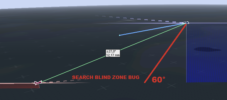
BUG STILL THERE, still radar can NOT detect any target bellow 27° look down angle. This is very important BUG. Please ED Fix it. Even F-16C with AN/APG-68 can in DCS to its limit of -30°, Tomcat can also scan in RWS to its radar elevation limit of -60° as the Hornet should! AN-APG-73_LOOK_DOWN_BUG.trk
-
Question regarding the SLAM-ER, SLAM, and AGM-62 w/ Datalink pod
GumidekCZ replied to Hammer1-1's topic in DCS: F/A-18C
Datalink DL-13 with AWW-13 pod described (notice the word about wingmen controll guidance and Datalink-13 range of 200 nm) On Hornet, there is picture from Gulf with AWW-13 carried on station 2 with Walleye carried on station 8. The imbalance was solved with wing external fuel tank carried on opposite side. -
Question regarding the SLAM-ER, SLAM, and AGM-62 w/ Datalink pod
GumidekCZ replied to Hammer1-1's topic in DCS: F/A-18C
Hi @BIGNEWY , we need budy datalink so much. There are couple of good reasons to have it asap. INRL in Hornet manual is described, that any release other than simultaneous (single or ripple) is PROHIBITED for weapons like AGM-62 Walleye / GBU-24 / MK-60 / MK-65. This is due to exceedign maximum authorized lateral weight asymmetry is 26,000 foot-pounds. EDIT: in video posted bellow, there can be seen multiple Hornet Walleye releases with only single drop from stations 2 or 8. I dont know if this was allowed only for testing purposes or not, also it cant be recognized from poor quality video, if it is Walleye I or II (big weight difference) - I suppose it was II (bigger and larger wings - so my next grey text is now not true exactly. We clearly see, that fight with Hornets trim and controls we are experiencing with every signle release form stations 2 and 8 was not alowed to do IRL. This insane flight control battle is result only of lack of Buddy Datalinked Guidance - which was promised to have so long time ago, that I cant even found the post. DCS Hornet MANUAL (page 298): "Pod Antenna Option. The A ANT option selects the aft antenna of the data link pod. It is boxed when selected. The selection allows forward and aft antenna control of the data link pod. This can be useful when self-guiding (aft antenna) or potentially guiding for another aircraft (forward antenna)." This is still not working in DCS Also would be such a great thing to have for AGM-84 SLAM/ER datalink DL13 guidance via AN/AWW-13 pod. -
Hi @IronMike, Can I reopen this bug report with one simple question? Why the HB gave us aprox exact over water 100 feet error all the time in every mission, when NAVAIR 01-F14AAP is clear with words: CAN READ and AS MUCH AS. So assume the error could be everywhere between Zero and 100 feet. If this was for example wave height dependant ... than it must be connected with wind speed ( DCS sea wave condition is dependant on it.)
-
You are true, the mass is used for damage calculation, so it should represent blast power - which is dependant od used explosive type. Many warheads and bombs than need to be revised, because the mass there fits its published explosive weight. Assuming that there is something stronger than TNT. Very nice source of information about warheads, blast power, fragment, chemicals, area of efect and many more: https://www.gichd.org/fileadmin/GICHD-resources/rec-documents/Explosive_weapon_effects_web.pdf
-
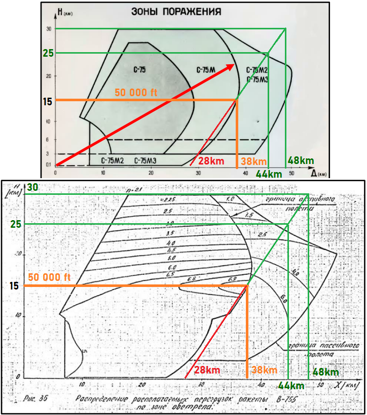
I couple of mission, I noticed that SA-2 range limits was reduced significantly - can be compared with an older SA-2 Desna system. So I went into DCS scritps and compared values there with the real world values for Volhov system with V-755 (20D) missile. SNR_75V.lua (Fan Song TR radar): beamWidth = 1.5707963267949, distanceMax = 100000, distanceMin = 1500, max_trg_alt = 20000, min_trg_alt = 25, S_75M_Volhov.lua (Launcher) ThreatRange = 43000, ThreatRangeMin = 7000, distanceMax = 43000, distanceMin = 7000, maxTargetDetectionRange = 65000 SA2V755.lua (V-755 20D missile) D_max = 40000, - Max Range at min Alt of 100m D_min = 7000, - Min Range H_max = 25000, - Max Altitude H_min = 100 , - Min Altitude KillDistance = 20, Nr_max = 17, PN_coeffs = { 2, 1000, 1, 40000, 0.5 }, Range_max = 30000, - Max Range at max Alt of 25km ccm_k0 = 3, 90° Degree Radar Beam? Wide Beam setting of FanSong radar was 20° Missile fuze was set to standard 100m, or can be set to 300m for large target like B-52. Max speed and overload capability (depending on target altitude): at 300m altitude, 785m/s (Mach2.6), 5.5~6g at 10km altitude, 910m/s (Mach3), 5.5~6.5g at 25km altitude, 1125m/s (Mach3.7), 2.7~3g at 30km altitude, 1230m/s (Mach4), 2.1~2.4g Missile guidance was able to guide via HALF-LEAD (PN=0.5) or LOS (on beam PN=0), never Pure Lead PN=1 Now to Missile limits. Lets say, that roof latitude for DCS aircrafts is 15km (50 000ft), so the aim of accuracy is to suit missile depicted Range limits to this altitude - orange lines. Green lines represent actual maximum limits of the missile with linear approximation between these values. New suggested missile values according to S-75M or V-755 20D missile charts: D_max = 28000, - Max Range at min Alt of 300 m D_min = 7000, - Min Range Correct H_max = 30000, - Max Altitude H_min = 300, - V-755 20D minimum altitude Range_max = 48000, - Max Range at max Alt of 30 km
-
- 1
-

-
More to crosswinds (NAVAIR 00-80T-104 NATOPS LSO MANUAL): Winds starboard of the angle also adversely affect recovery conditions. The burble, aft of the ramp, becomes stronger and moves closer to the ship as the magnitude of recovery crosswind is increased. The airflow disturbance requires corrective pilot technique if the recovery crosswind exceeds 7 knots for all carriers. Even with corrective pilot technique, sinking speeds 3 to 6 feet per second in excess of those experienced during normal (no recovery crosswind) operations can be expected. For these reasons, recovery headwind should be maintained as closely as possible to the optimum velocity and the centerline of the landing area. Shipboard aircraft recovery operations with recovery crosswinds in excess of those specified should be avoided. Refer to Aircraft Recovery Bulletin No. 10-10. Informative call by LSO to describe wind direction: “Winds are (slightly) starboard/port/axial.”
-
Can I ask to have at least fixed missions (Hornet 1989-OCA.miz) where carrier is traveling at recovery time with winds blowing from starbord? Or was this also common WOD direction? Slower WOD speed still can provide safe recover, but some rules needs to be kept in mind. From F/A-18's manual: "With a 30-knot wind over the deck begin the 180° turn to the final approach when approximately abeam the LSO platform." I have from Vincent Aiello confirmed, that at slower WOD speeds, they were used to estimate WOD strength according to ship wake and sea waves, all that to maintain groove time around 15-17 seconds. Here is another WOD info source from Real Hornet pilot Lex Talionis, how important WOD is.
-
Walleye II warhead have in DCS defined mass of its predecesor Walleye I, expl_mass = 365.6, mass = 365.6, Should be 900 kg (special linear shadped charge able to create multiderctional high energy basts) info about that is available here, and Wiki.
-
According to these public data : http://cdn.ihs.com/Janes/Sample-content-IHS-Janes-Weapons-Air-Launched.pdf the Dekas missile has wrong data in: Nr_max = 40, - According to data CATIC 2011 should have only 35g limit Damage = 46.75, - according to increased WH weight +1.5 kg, this should be 28.75 (AIM-9M have = 25, with warhead mass = 10) expl_mass = 18.7, - Correct value is 11.5 kg (25 lb) HE fragmentation mass = 18.7, - again 11.5 kg piercing_mass = 3.74 - also need to be lowered
-
R-73 and R-27T/ET flares resistance revision
GumidekCZ replied to 85th_Maverick's topic in Sim Research
Take a look into my report. There is much more wrong about FLARES and IR guided missile flare rejection inconsistency. Other than throttle setting, it depends on range/time to target - at close range FLAREs becomes almost useles, Why? any real physics behind it? -
Neither F-16 or F-18 have damage model simulation completed (like ww2 have). It's something will be worked on. Nobody will tell you when, but I have small whish to be completed at least at Q4 2022.