
GumidekCZ
-
Posts
870 -
Joined
-
Last visited
Content Type
Profiles
Forums
Events
Everything posted by GumidekCZ
-

reported AGM-84D Harpoon TRUE heading flight path BUG
GumidekCZ replied to GumidekCZ's topic in Bugs and Problems
Because My June 2020 report still not solved and I found even more strange BUG behaviour, Im opening new report topic. Old one: Me flying MAG 270° (Caucasus map 276,2° TRUE), Harpoon set by UFC to fly MAG 270°, but instead of that, Harpoon fly its TRUE HDG 270° New find: Me flying MAG 260° (Caucasus map 266° TRUE), (Avionics set to MAG) Harpoon in BOL mode set by UFC to fly bearing 260° Than I switched avionics to TRUE and on HSI the line of Harpoon flightpath is correct ... 260° of TRUE, but after launch, the Harpoon will fly 254° TRUE. Thats radiculous! The missile should fly on type of bearing (MAG or TRUE) selected in avionics in time of bearing enterd in UFC. If MAG/TRUE changed in A/C HSI page after that, nothing should change - the bearing is already in memory of Harpoon INS. There is no command that should change it. track attached Harpoon_BOL_bearing_BUG.trk -
Mi-8 & Mi-24 main rotor Swash Plate wrong motion
GumidekCZ replied to GumidekCZ's topic in Bugs and Problems
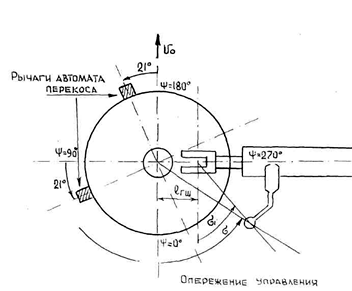
Well, this document for Mi-8 describes in more detail everything I tried to explain above. Aerodynamics_Mi8.docx Особенностью работы НВ является инерционность его лопастей. Поэтому начало взмаха лопасти отстаёт от начала изменения угла установки на угол азимута приблизительно 90° −σк, где σк − характеристика регулятора взмаха. Это создаёт неудобство управления, так как не обеспечивается независимость каналов управления вертолетом. Конструкция системы продольно- поперечного управления вертолетом включает в себя так называемое опережение управления, назначение которого: -обеспечить полное соответствие наклона равнодействующей НВ Rн отклонению ручки циклического шага (РЦШ); -исключить взаимовлияние продольного и поперечного каналов управления, вызванное инерционностью лопастей. Опережение обеспечивается: смещением пальцев крепления тяг продольно-поперечного управления на 21° против вращения НВ (рис. 32), а также подбором характеристики регулятора взмаха (угла σ). TRANSLATED: A special feature of the main rotor operation is the inertia of its blades. Therefore, the beginning of blade sweep lags behind the beginning of attitude angle change by an azimuth angle of approximately 90° -σk, where σk is the characteristic of the sweep regulator. This creates inconvenience control, as it does not provide independence of helicopter control channels. The design of the system of longitudinal and transverse control of the helicopter includes the so-called control advance, the purpose of which: - provide a full correspondence of the slope of the equinoctial force of main rotor disc Rn to the deviation of the cyclic pitch stick; - exclude mutual influence of longitudinal and transverse control channels caused by blade inertia. The advance is provided by: shifting the longitudinal-transverse control linkage pins by 21° against main rotor rotation (Fig. 32), as well as by selecting the sweep regulator characteristic (angle σ). Fig. 32 Control advance mechanism
-
Mi-8 & Mi-24 main rotor Swash Plate wrong motion
GumidekCZ replied to GumidekCZ's topic in Bugs and Problems
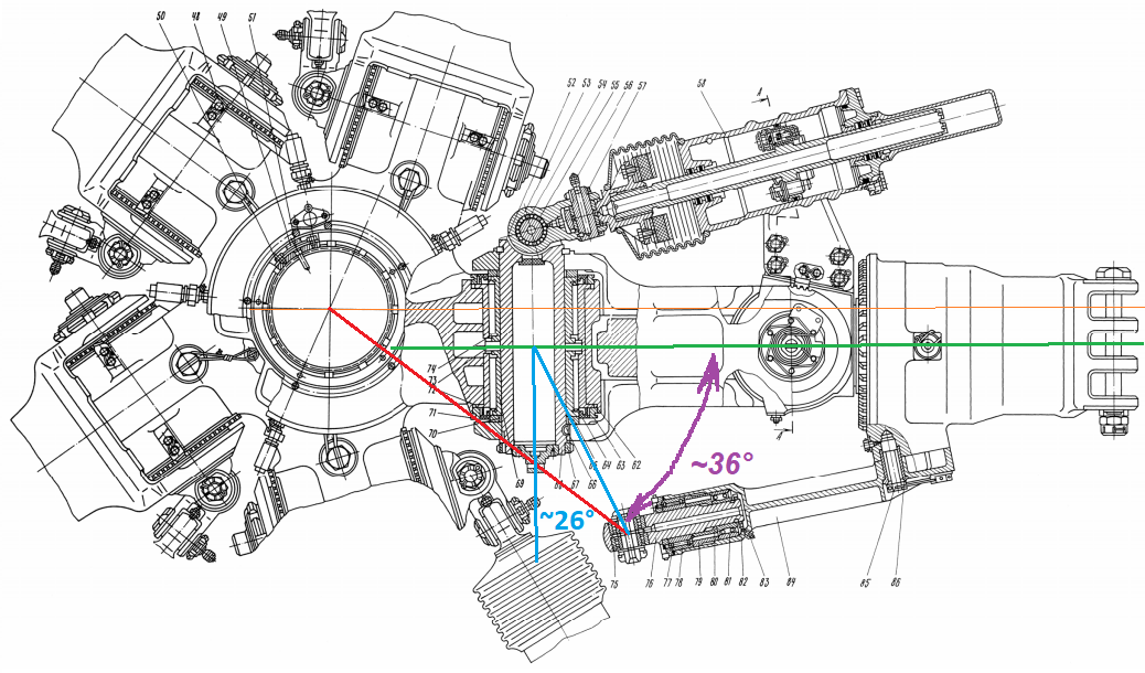
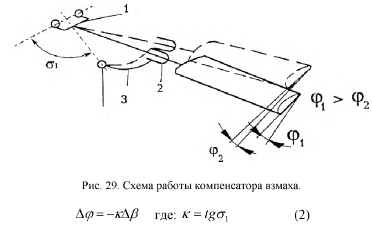
Drawing from which I measured the angle of pitch horns 36° (Tau) and falp stiffening angle 26° (Sigma) HOW THE ANGLE σ1 BETWEEN PITCH HORN AND HORIZONTAL (FLAPPING) HINDGE IS AFFECTING THE BLADE ANGLE ф : (ΔΨупр - is the offset angle of swash plate control = for Mi-8/24 it is the 21° ) Угол опережения изменения циклического шага лопасти определяется коэффициентом компенсатора взмаха лопасти (к), углом поводка лопасти σ11 и средним углом поворота (отставания) С0 лопасти относительно вертикального шарнира [6]: ΔΨупр =< σ11 - С0 - arctg(k) (1) Компенсатор взмаха в системе управления лопастями несущего винта (рис.29) - это особая кинематическая связь угла установки лопасти ф от угла взмаха лопасти β НВ при ее вращении в своей плоскости, обеспечивающая автоматическое уменьшение угла установки лопасти при взмахе вверх и увеличение его при опускании лопасти. Это нужно для регулирования и ограни чения взмаха лопасти в плоскости ее вращения. DeepL translation: The advance angle of the blade cyclic pitch change is determined by the blade sweep compensator coefficient (k), the blade leash angle σ11 and the average angle of rotation (lag) С0 of the blade relative to the vertical joint [6]: ΔΨупр =< σ11 - С0 - arctg(k) (1) The blade sweep compensator in the main rotor blade control system (Fig.29) is a special kinematic link between the blade setting angle ф and the blade sweep angle β HB during its rotation in its plane, which provides automatic reduction of the blade setting angle during upward sweep and its increase during blade descent. This is necessary to regulate and limit the blade sweep in the plane of rotation.
-
Mi-8 & Mi-24 main rotor Swash Plate wrong motion
GumidekCZ replied to GumidekCZ's topic in Bugs and Problems
Better drawing, with Mi-8/24 offset angle of wash plate precceding control ΔΨупр = 21°.
-
Mi-8 & Mi-24 main rotor Swash Plate wrong motion
GumidekCZ replied to GumidekCZ's topic in Bugs and Problems
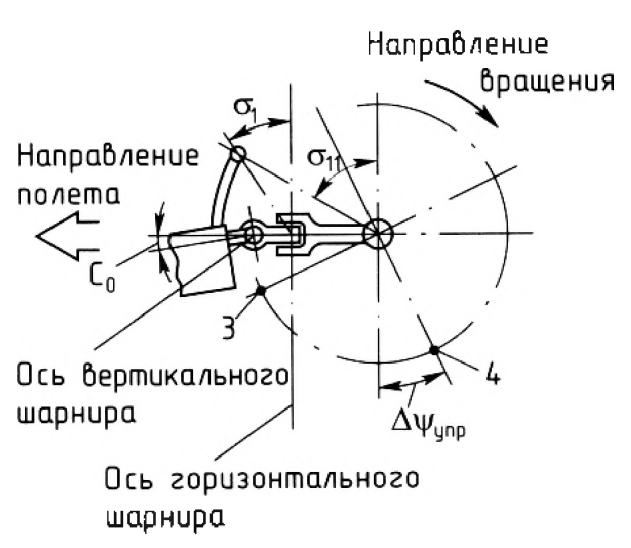
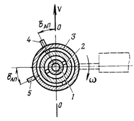
in attached doc on page 28 (this graphic not representing Mi-8 control) Рис. 8.18. Угол опережения автомата перекоса: Величина угла опережения автомата перекоса у разных вертолетов различна и находится в пределах 20-26° (у вертолета Ми-8 dАП =21°). При отклонении ручки продольно-поперечного управления, например, вперед наружное кольцо с тарелкой ввиду наличия угла опережения отклонится вперед и влево, а конус вращения несущего винта в результате циклического изменения установочного угла лопастей отклонится строго вперед. Translation: Fig. 8.18. The advance angle of the automatic skew control unit: The value of the advance angle of the automatic tilt control unit varies from helicopter to helicopter and is in the range of 20-26° (Mi-8 helicopter dAP =21°). When the longitudinal-transverse control handle is deflected, for example, forward, the outer ring with the plate, due to the presence of an advance angle, will deflect forward and to the left, and the cone of rotation of the main rotor will deflect strictly forward as a result of a cyclic change in the installation angle of the blades. Source: 8. Управление вертолетом Ми-8.doc
-
Mi-8 & Mi-24 main rotor Swash Plate wrong motion
GumidekCZ replied to GumidekCZ's topic in Bugs and Problems
From the swash plate actuators position. Red - pitch control Blue - transversal (roll) control Both channels works independently on each other. Not like in DCS now, where if you push cyclic forward - both with actuate = wrong.
-
Mi-8 & Mi-24 main rotor Swash Plate wrong motion
GumidekCZ replied to GumidekCZ's topic in Bugs and Problems
I´ve got it! I have found explanation in Czech Technical University Bachelor thesis (Google translator or any other comes handy): https://core.ac.uk/download/pdf/30291859.pdf There is an angle between axis of (flapping) horizontal hindge and pitch horn (point A) - in picture angle designated as Delta According to Mi-8 aerodynamic manual 0,5 = tan(Delta) , so the Delta = 26,6° This angle decrease desired 90° angle. As measured by myself from drawing, it equals roughly to 36° So well known Mi-8 swash plate offset angle 21°(Delta) + Angle of pitch horns 36° (Tau) + above described lag angle 26,6° (Sigma) = 83° almost our desired 90° Note: my angular measure were dony only on my laptop screen with help of some tools and probably have some errors. SWASH PLATE BUG - fix axis of movement for lateral and longitudal tilt by 21° CCW. Keep rotor disc animation as it is now. Mi-24 Hind have identical main rotor hub and swash plate machinsm with same angles as described above. -
Mi-8 & Mi-24 main rotor Swash Plate wrong motion
GumidekCZ replied to GumidekCZ's topic in Bugs and Problems
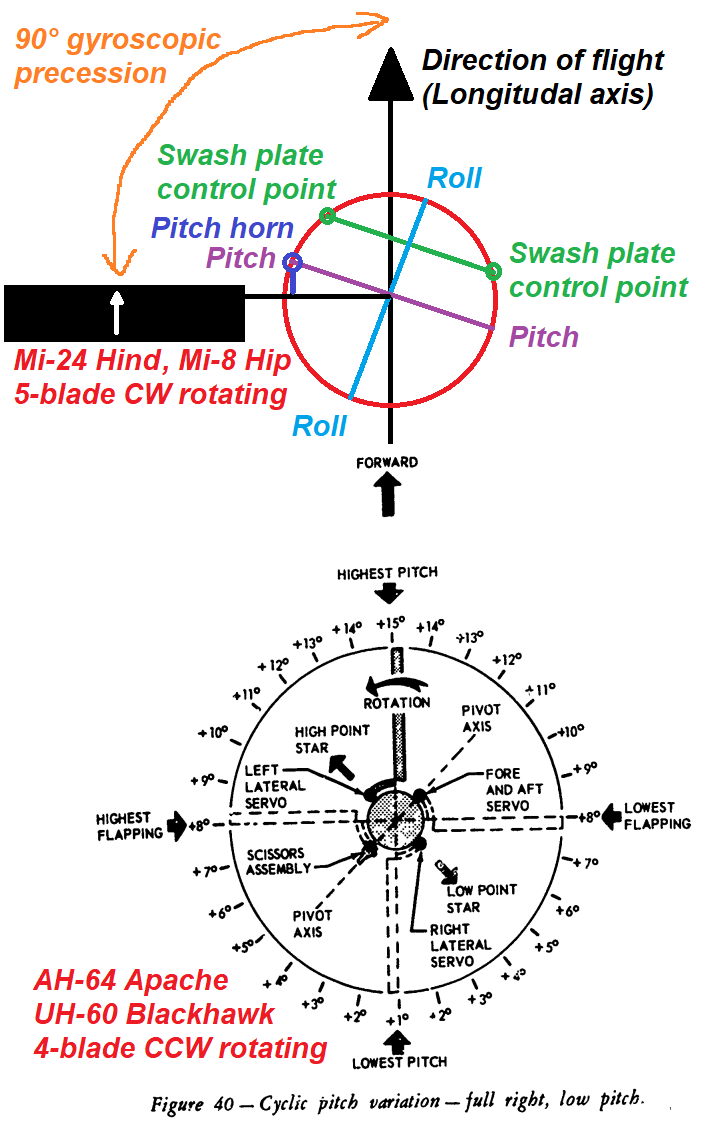
Swash plate never have 90 degree tilt offset because part of 90 degree angle will account to pitch horn angle offset. At Apache and Blackhawk it's exactly 45 degree swash plate +45 degree pitch horn. Gyroscopic momentum Always act in axis perpendicular to rotation and force applied. The swash plate have most common tilt offset of 180 divided by # of blades. Look at 3, 4 or 5 blades rotors and you will see that it's matches. -
@NineLine, please move this topic into Mi-8 Bug reports forum section. My mistake. Many thanks.
-
Simply, the swash plate is controlled so its tilted 90° precceding the tilt of rotating blade disc due to compensation of Gyroscopic precession effect. !!! EDIT: NOT EXACTLY TRUE - SOLUTION IS DESCRIBED BY ME IN THE TOPIC DOWN BELLOW !!! In DCS the movement of swash plate and rotor blade disc is in same plane - WRONG. SIKORSKY_HELICOPTER_FLIGHT_THEORY FOR PILOTS AND MECHANICS - ADA119096 - starting at page 27 Mi8_swash_plate_BUG.trk Mi-24_swash_plate_BUG.trk In the video bellow, when the swash plate tilted to the side, the blade disc in flight will be tilted forward or aft - controlling the PITCH.
-
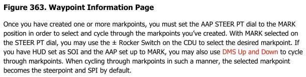
reported CDU MISSION dial page shows created Markpoints
GumidekCZ replied to GumidekCZ's topic in Bugs and Problems
I think, that it is still a BUG, proper way how it should work can be now achieved only by selecting WP FSK - then STEERPOINT - then WP FSK again - and now WAYPOINT ... here the created mark points and waypoints can be cycled as they should from the start, not only by going through here described process. In my track, Im again trying cycle to saved waypoints, but without success, but then I use the above described process and voala, CDU WAYPOINT page working like it should be. A-10C_CDU_WP_page_BUG.trk -
reported CDU MISSION dial page shows created Markpoints
GumidekCZ replied to GumidekCZ's topic in Bugs and Problems
@Lord Vader I mentioned OTHER just as additional description of CDU setup. The bug report is about WAYPOINT page and inability to cycle through waypoints by +/- rocker (as described in both manuals) after Mark point is created. -
reported CDU MISSION dial page shows created Markpoints
GumidekCZ replied to GumidekCZ's topic in Bugs and Problems
@Lord Vader My problem is, that when STEER PT dial set to MISSION, than when markpoint created then the CDU screen somehow (bug) switch like if the STEER PT dial is set to MARK, without abylity se cycle there by +/- rocker between waypoints, only markpoints can be selected there. Now switching STEER PT dial between MISSION and MARK show the same and have same behaviour - acts as identical page. No waypoints shown. I've been going through the Baltics TEW 3.0 campaign for the past few months and I'm pretty sure this behavior wasn't there before the 2.9 update. I had been able to cycle through all waypoints AND markpoints. As RW and DCS manual says: - Not able to do so, after markpoint created.
-
reported CDU MISSION dial page shows created Markpoints
GumidekCZ posted a topic in Bugs and Problems
CDU STEEP PT dial set to MISSION and PAGE dial set to OTHER, Waypoints suddenly dissappear, only Markpoints there. It should appear only when STEER PT se to MARK as manual says. A-10C_CDU_Waypoint_page_BUG.trk
-
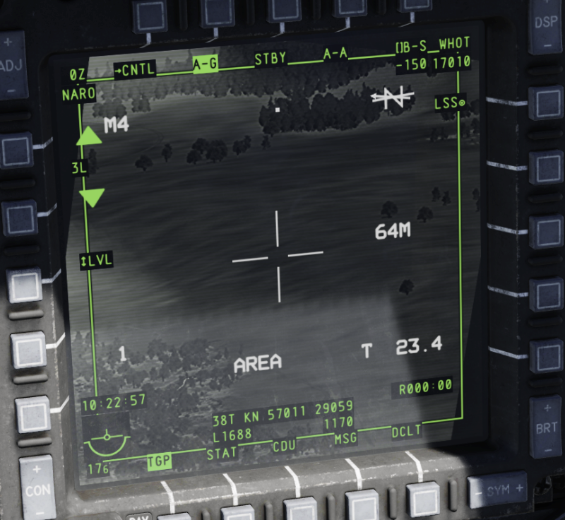
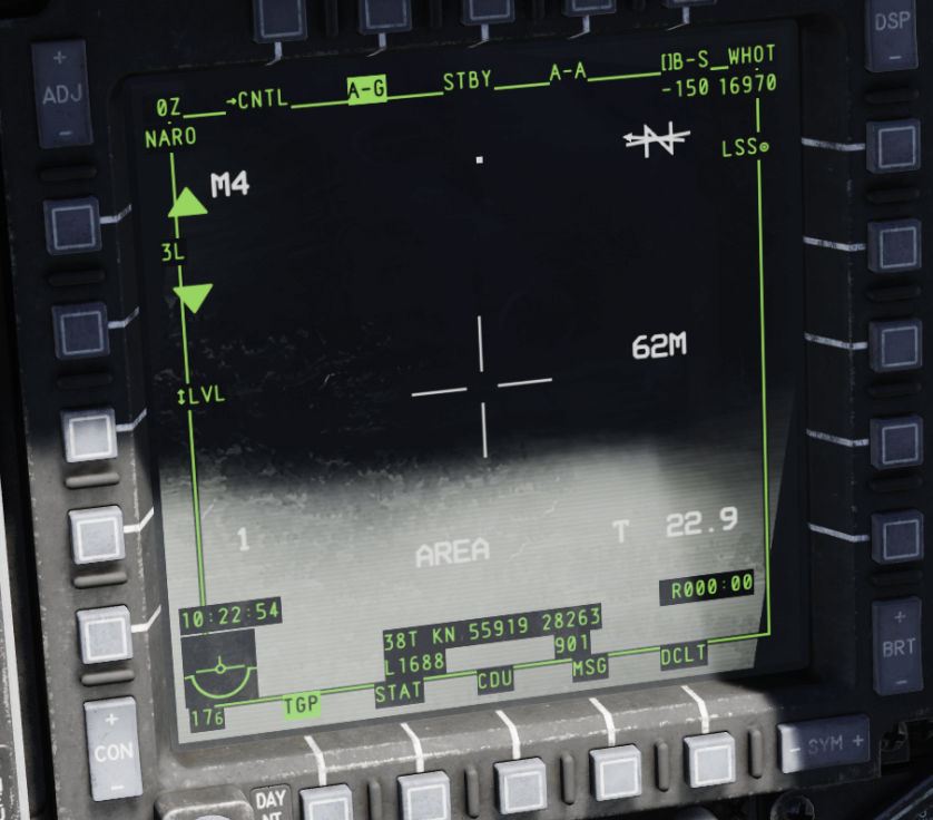
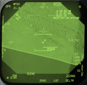
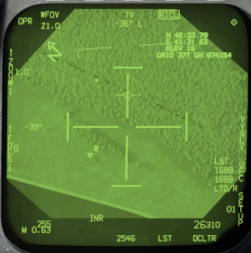
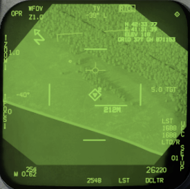
wip LITENING pod non-existing auto gain with DCS clouds
GumidekCZ posted a topic in Bugs and Problems
I have found NO evidence, of LITETING pod ability to Auto adjust the Gain & Level like Im experiencing today in DCS A-10C. When Im working on targets and clouds near by, Im about to Quit the mission, because this bug will spoil my enjoy from the mission. A-10C_LITENING_IR_BUG.trk This bug can be found across entire range of DCS IR sensors. EDGE OF CLOUD (Black&White BUG ): THEN I SLEW UP A LITTLE (now without the cloud its correct again):
-
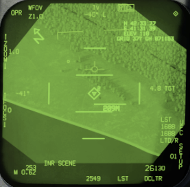
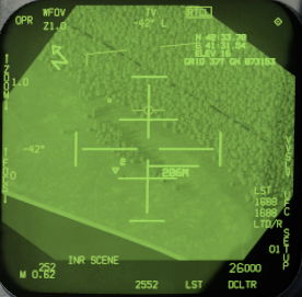
ATFLIR_UNDESIGNATE_from_SCENE_then-slew_to_WP.trk When ATFLIR is at SCENE mode and UNDESIGNATE is pressed it will make snowplow mode (according to a1-f18ac-746-100-atflir-principles-of-operation I think point mode should be engaged (diamond)). But this is not the reported bug yet... -> Then if you designate a waypoint as a TGT and press TDC SLEW, it will make INR SCENE mode - this mode cannot be made by any other method. -> Then if UNDESIGNATE is pressed, it will become Snowplow SCENE = first bug, if you pressed UNDESIGNATE again, it will go to designated SCENE mode - which will be NOT ground stabilized and will drift away as snowplow mode = second bug. The Snowplow mode now cannot be angaged by pressing UNDESIGNATE = third bug. To do so, you have to press TDC to gound stabilize the drifting diamond and then press UNDESIGNATE. ->
-
When you have slaved ATFLIR to waypoint, TGT boxed on HSI or SA page (ATFLIR diamond), and you want to slew designation - so IF you will press slew command to any side before actualy pressing TDC button, than your point INR track will change to snowplow mode and will run away from target area. This need to be fixed, and slew command need to only slew designation. ADVICE for players at current BUG situation: To successfully slew, YOU HAVE TO NOT PRESS SLEW BEFORE TDC PRESS. If you press TDC and only then SLEW, it will work fine ATFLIR_slew-at-WP-boresight_tdc-depr_slew.trk
-
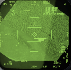
When you designate target by ATFLIR, and cycle through SCENE or AUTO modes, then pressing single UNDESIGNATE (not to engage VVSLV), ATFLIR will stay in INR diamond designation - only the boxed TGT will change to WPT as seen on picture bellow. THIS BUG IS AGAINST THE ED HOW ATFLIR SHOULD WORK, BUT I THINK THING THAT SNOWPLOW MODE SHOULD BE POSSIBLE TO ENGAGE ONLY FROM VVSLV MODE AND THIS REPORTED BUG IS ACTUALLY WAY IT SHOULD WORK IRL - unfortunately I have no evidence for that - You can help to find some. ATFLIR Manual: a1-f18ac-746-100-atflir-principles-of-operation is mentioning, that undesignate from designated target commands ATFLIR to point. null
-
When Mk82 / 83 / 84 selected, target designated (CCRP mode active) and then if you press UNDESIGNATE at any of ATFLIR track modes, or without them -> ATFLIR will imediately SLEW hundreds miles away instead of following computed CCIP point. Works fine for other types of weapons. ATFLIR_not_floowing_bomb_CCIP.trk
-
1) Acquisition box is completely missing (from day DCS ATFLIR release) when engaging or adjusting auto track. From video bellow can be seen, how it is changing its size while trying to acquire the contrast shape to track. It is also mentioned as a picture at ATFLIR Manual: a1-f18ac-746-100-atflir-principles-of-operation. 2) Pressing and holding TDC button for offset is wrong in DCS. There is no tiny little cross, and ATFLIR offset focus is cross centered. OFFSET behaviour also here, in very well known video... little horizontaly stretched, but still good enough.
-
My question for all Hornet users and players: DO YOU THINK, DCS HORNET HAVE ENOUGH RUDDER RESPONSE IN ITS CURRENT FLIGHT MODEL??? Can you do same things as these guys -- without asymetric thrust -- : Just if you fly straight and apply full rudder, the nose will slide at the start about 4 deg to side and seconds after only 3 degress off the flight path. Over all the plane will still be flying almost straight ahead without rolling or yawing because the flight computer will be against you, even if FCS GAIN OVERRIDE switch engaged of paddle pressed.
-
In "MANY" DCS Hornet missions in editor # of CHaffs and Flares is LOW, ...check numbers in mission editor or in mission on MFD page... PLEASE ED, FIX THIS- NOT only for player Hornet, but for all AI Hornets in missions as well. THX BVR 8vs8 BFM MiG-29 missions ACM 4 vs 4 MiG-29 Any Hornet 1989 mission is 30 Flares less DACT Gauntlet Magnum Force Caucasus FA-18C Defensive Systems.miz - Really funny that here you have just 30 CHAFFs and 15 FLAREs Red Flag Iron Hand ... ... null
- 1 reply
-
- 1
-

-
As title say. Really STUPID action can result from this bug, if two tankers fly near by one is low on fuel with "RTB on bingo fuel" but the AI will command to refuel at nearest tanker instead of RTB. Bingo tankBINGO RTB BUG.trker is parasiting on next tanker
-
Track needed, do you remeber?
-
Main wheels rotates wrong speed when rolling
GumidekCZ replied to GumidekCZ's topic in Bugs and Problems
Fw-190D opossite issue. Wheels spin Too Fast. Bf109 OK.