Dropship Pilot
-
Posts
255 -
Joined
-
Last visited
Content Type
Profiles
Forums
Events
Everything posted by Dropship Pilot
-
I think it's this kind of switch: interlocking-latching-push-button-switch However, the F-14 version has the additional rotating square collar. Cheers, DSP
-
Great job on the new cockpit! :thumbup: This is surely no gamebreaking bug. However, as you are currently working on the A-10C I'd like to point it out: If you look at the comparison picture below, you'll notice that the real light panel as well as the DZUS studs are much higher than in the model. The original backplate is 0.064" (1.6mm) thick. This seems perfectly ok in the model. The light plate in the model is only slightly thicker (like maybe 2mm). The original light plate however is about 3 times thicker than the one in the model. Typical light plate thickness is 0.25" (6,35mm). Some panels have even thicker light plates (the CDU is an extreme example). The same goes for the DZUS studs. The original ones are 0,375"diameter x 0,285" high (9.525mm x 7.24mm) as shown in MIL-F-25173. In the model it looks more like 9.525mm x 3mm. This may be old news and there may be reason why the panels are modeled like this. However, I think it takes some of the 3D effekt out of the cockpit which is especially noticeable in VR. This isn't limited to the A-10C by the way - I noticed it on other western planes as well as the Huey. I hope this helps. Cheers, DSP

-
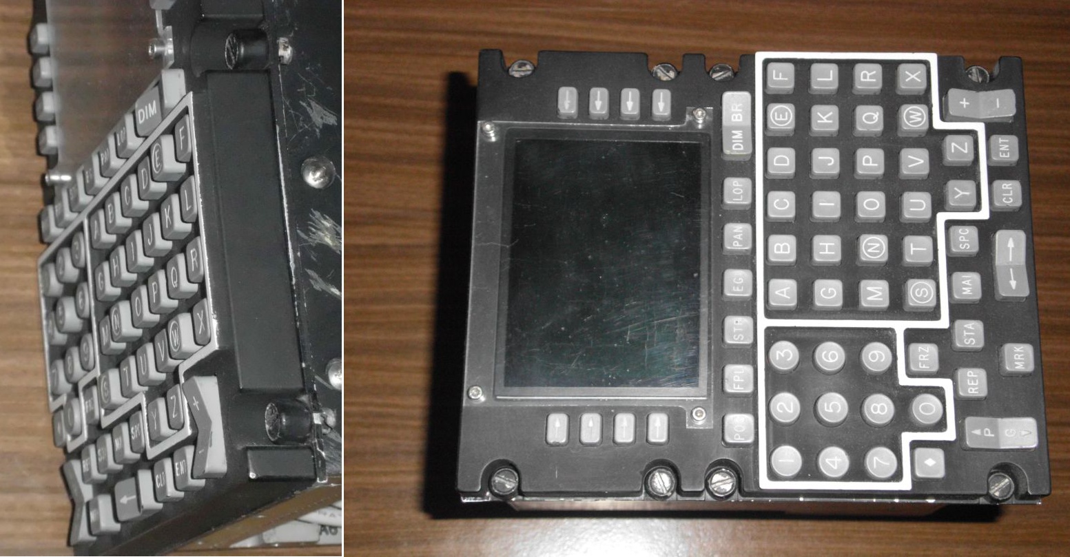
Here's a picture of the CDU I have. The NSN number is 6605-99-126-3140. On the left you can see that the number keys 5 and 0 as well as the letter keys W, E, S and N are raised. If you look closely you can see this also here: Sadly, I don't have an image that shows an A-10C cockpit at night. So there's no way for me to prove the claim about the frame being just painted white. Cheers, DSP
-

[REPORTED]New Cockpit: Windscreen Center Glass
Dropship Pilot replied to Snoopy's topic in Bugs and Problems
Hmm, maybe I'm looking for the wrong thing. Are the red marked stripes actual parts or an optical effect from the cannopy glass/frame (somewhat like on the 190)? Cheers, DSP -
[REPORTED]New Cockpit: Windscreen Center Glass
Dropship Pilot replied to Snoopy's topic in Bugs and Problems
Hi Snoopy, do you have other images showing this or do you know what it is for? I ask because had a look at several youtube videos and none showed this. Could it be just momentary (e.g. servicing)? Cheers, DSP -
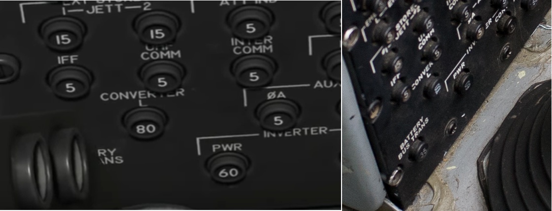
As you are working on the new cockpit (great job so far! ) I thought I'd point out some details that seem off: There's a small details that is wrong even in the flight manual - the CONVERTER L and the PWR circuit breakers are rotated 90 degrees counterclockwise compared to the other circuit breakers. Circuit Breaker.jpg The reason for this is that these high amp breakers are much larger and won't fit in the normal orientation. This is true for the A-10C as well as the A-10A. Also, as can be seen from the picture, the A-10C has the CONVERTER L Circuit breaker updated to 100Amps form 80Amps on the A-10A. Hope this helps. Cheers, DSP
-
As you are working on the new cockpit (great job so far! ) I thought I'd point out some details that seem off: The white border around the keypad and the number pad is NOT backlit on the real CDU. I have an original CDU of the same series and the front panel is solid black plastic with the white border painted on. Only the buttons are backlit! Please check this with a subject matter expert, but I'm very sure that it's the same for the CDU of the A-10. The indent on the keys is barely noticeable on the original keys. Its quite exaggerated (too much bump-mapping with a too hard border) in the new model which makes the lettering hard to read especially in VR. The Number 5 key as well as the W,N,S and E keys are about 1mm higher than the other keys. It's barely noticeable if you don't know about it. Hope this helps. Cheers, DSP
-
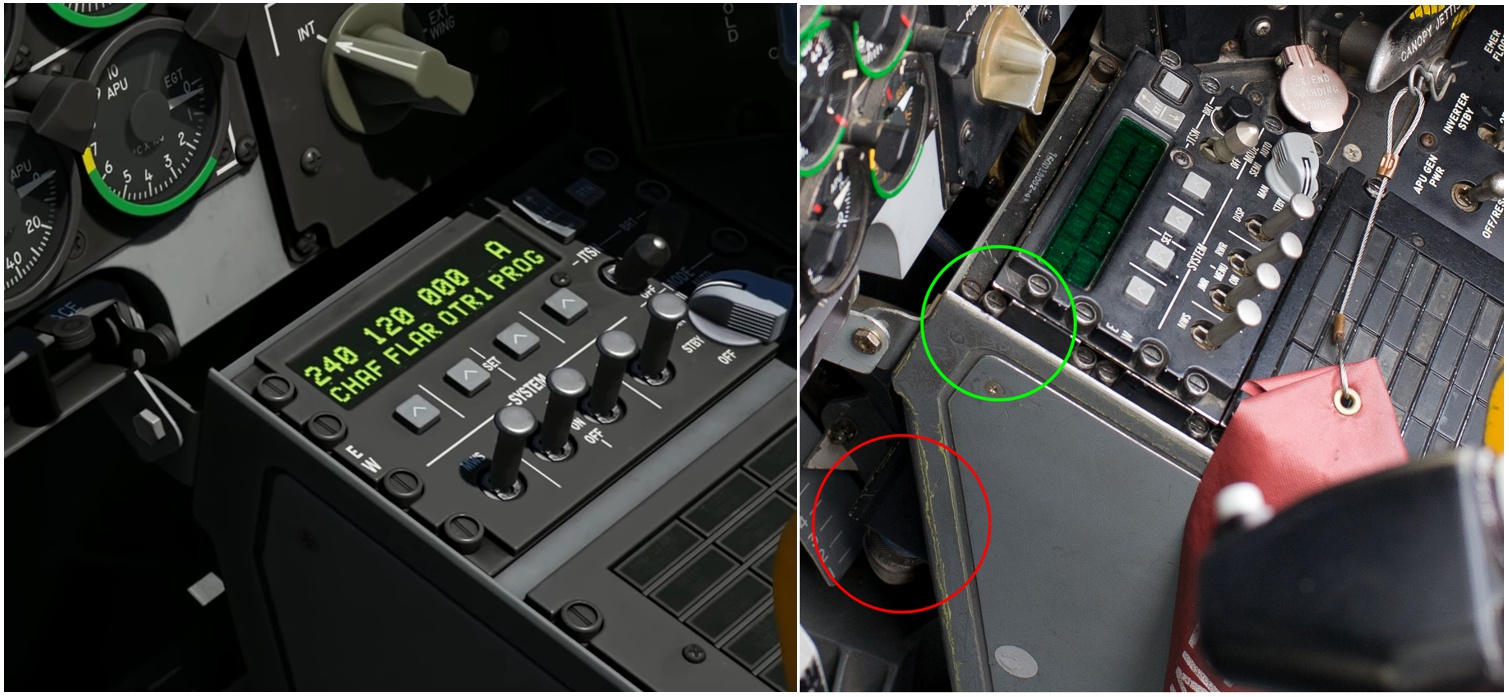
As you are working on the new cockpit (great job so far! ) I thought I'd point out some details that seem off: The following comparison picture shows, that the EW-Panel in the new model is 1 DZUS unit (9.525mm) too far to the front. There should be a blank 1-DZUS panel first, then the EW panel which meets directly with the Caution Lights panel. Also, both the Caution Lights panel as well as the EW panel are placed on Spacers that are about 15mm high (green circle) EW-Position.jpg The reason for these can be seen in the red circle: The housing of the EW-panel is so long that it will interfere with the rudder mechanics if mounted without spacers or in the first position of the DZUS-rail. Hope this helps. Cheers, DSP
-
[REPORTED]New Cockpit: Emergengy Chute safety pin
Dropship Pilot posted a topic in Bugs and Problems
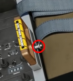
As you are working on the new cockpit (great job so far! ) I thought I'd point out some details that seem off: The Safety Pin for the Emergency Manual Chute handle should be removed during flight. :smilewink: Safety Pin.jpg Cheers, DSP
-
As you are working on the new cockpit (great job so far! ) I thought I'd point out some details that seem off: The Shoulder Harness lever on the left side of the ACES II is spring loaded so that it is either in the full forward or full back position. The center position (as shown in the new model) is not possible without holding the knob in this position. Hope this helps. Cheers, DSP
-
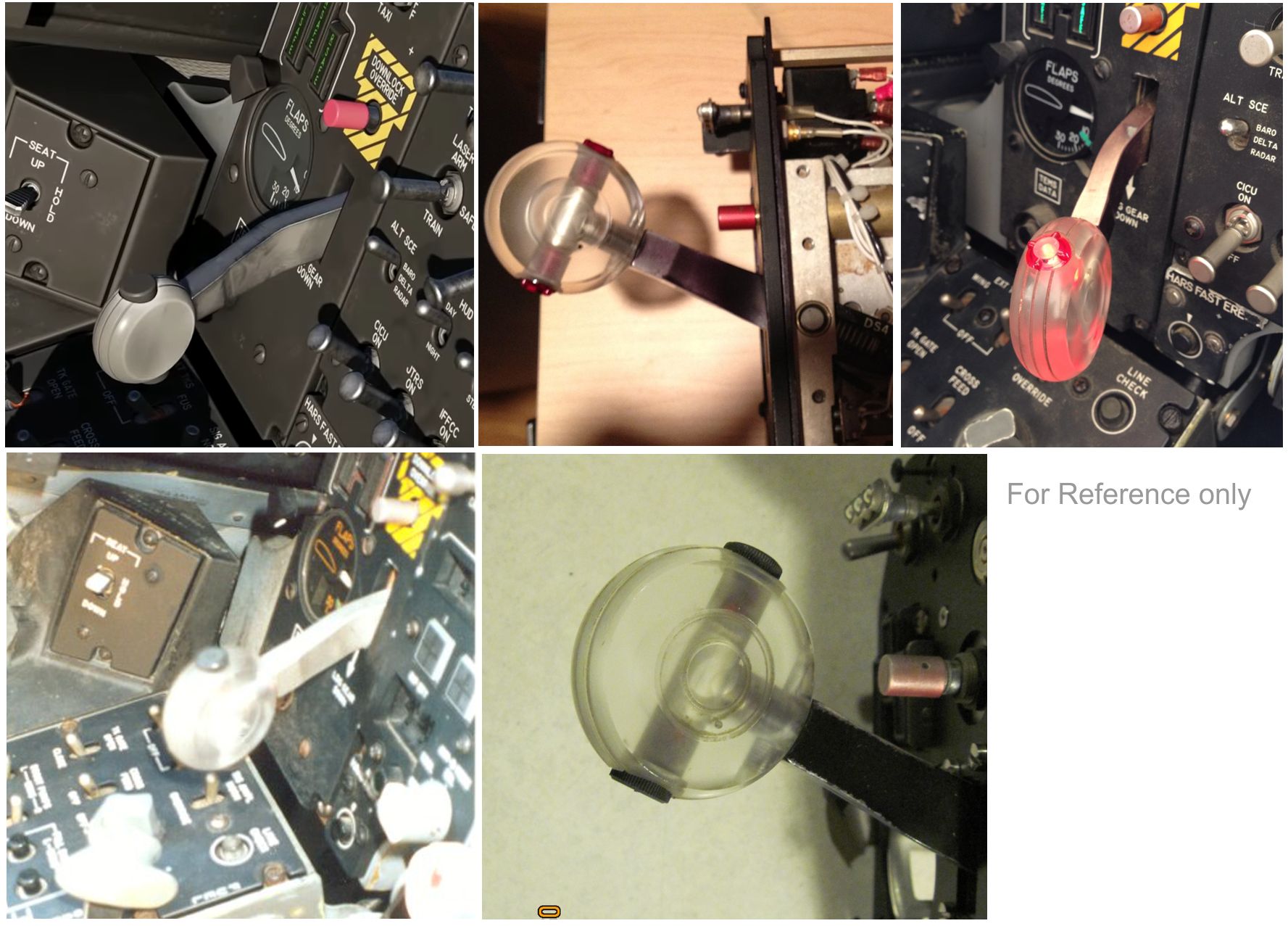
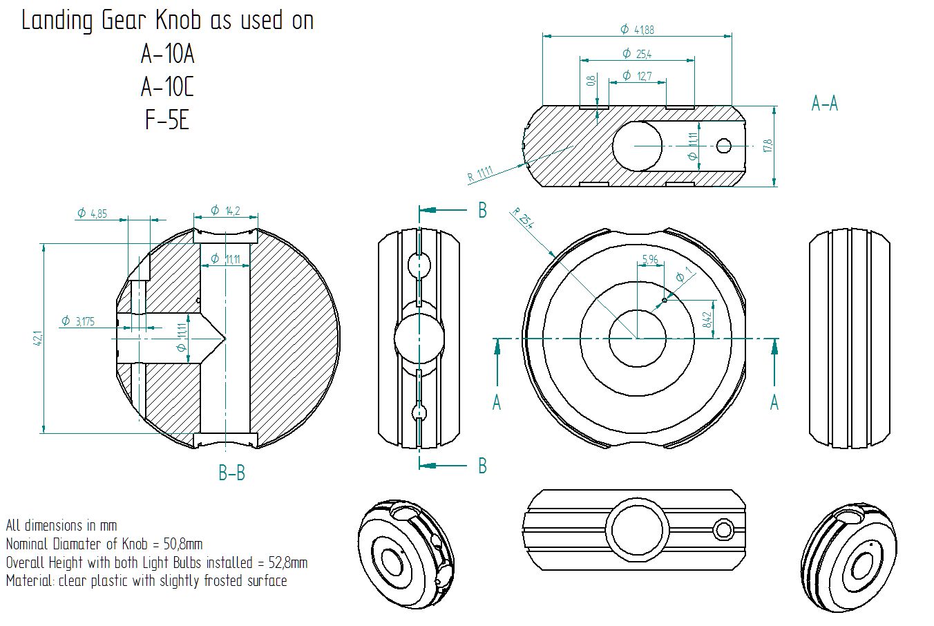
As you are working on the new cockpit (great job so far! :thumbup:) I thought I'd point out some details that seem off: In this case the proportions of the landing gear lever/knob. The following picture shows a comparison of the new model with some the real deal. Landing Gear Knob References.jpg As you can seem the round knob seems to be too small compared to the lever and the black inserts (light bulbs). Also the circular cutouts on the sides of the knob are missing (texture?) as well as the whole knob doesn't appear transparent. The following drawing was based on dimensions taken from a real knob with a caliper - so these should be quite accurate: Landing Gear Knob.jpg Sadly, I don't have the complete lever assembly, so I can't provide any dimensions on the lever itself. User Gadroc had some on this website, but the link has gone dead. Feel free to contact me if I missed a dimension or if you need pictures/details on the knob. I hope this is of some help. Cheers DSP
-
Ah, now it starts making sense - so you operate the switches at the at the end (top/right) with thumb stretched out and the ones on the bottom with the bend thumb. Thanks a lot! :thumbup: Cheers, DSP
-
Marcq, I see where you come from as there's no arc section on the throttle lever, while there's one for the nozzle and nozzle stop levers. However, if you have a closer look at the lever of the throttle, you can see that it points toward the same axis as the other levers. For the nozzle stop lever, you need the arc to make it lock into position. On the throttle, there is no need for the arc and that makes it look like its linear actuated. The reason for most throttles to be rotation based is that it's much easier to build a smooth and reliable rotational axis compared to a translational axis. A rotational bearing can easily be completely sealed, while it takes much more effort/space to protect the linear rail from dirt and damage. You should also keep in mind, that the real throttle levers are usually much longer (3-4 times) as on "our" setups (TM Warthog for example). This makes the motion equally much more linear (you can think of a linear motion as a rotation about an axis that is at infinity). What puzzles me more about the Harrier throttle is how you operate the switches at the bottom of the throttle handle (e.g. Comms and Air Brake). How do you reach those? Your fingers won't reach that far around the throttle grip and could interfere with the switches at the front and for the thumb it's also no easy to reach position. :huh: Cheers, DSP
-
There have been several downloads of the mission files - can anyone confirm this behaviour? Cheers, DSP
-
Hi, everyone! I'm using DCS stable version 2.5.5.34864 and the Huey. For my Huey missions I'd like to play some random background music. So I was experimenting with the Radio Transmission function and found the following behaviour: 1. Start radio transmission for tigger zone A 2. Stop radio transmission after 9 sec (short length for test) 3. Start radio transmission for tigger zone A 1 sec later 4. Stop radio transmission after 9 sec This works 3 times for trigger zone A. In the 4th cycled no more sound is played! If I then use a differend trigger zone B, the sound is played again. See the attached RadioTestB3.miz Things become even more interesting if I cut the sound file down to 20sec. Thus it is still longer than the 9 seconds play time, but now I can repeat it 5 times (maybe more) without problem. See RadioTestB4.miz Can anyone please explain what's going on? Is there a way to make this work consistenly? Cheers, DSP RadioTestB3.miz RadioTestB4.miz
-
Here's some data for the F-18: Left/right: +/-3" on a radius of 12.493" Front/Back: +2.5"/-5" on a radius of 18.529" The radius given is from the point of swivel to height of the middle finger. As you can see from the data the F-18 has two differend points of swivel 6.036" above each other. Cheers, DSP
-
The seat angles for the differend ACES II (A-10, F-15, F-16) versions are given here: https://apps.dtic.mil/dtic/tr/fulltext/u2/a133628.pdf It also has some other usefull dimensions.... :smilewink: Cheers, Stefan
-
Hi John, you are doing a great job with your panels! :thumbup: There's one thing I don't understand, however - why are you using two pots for the temperature control instead of a double shaft pot (like the Bourns PTH901-030S-103B1) ? Cheers, Stefan
-
Great stuff! :thumbup: Cheers, DSP
-
Ah! Cool! :thumbup: Cheers DSP
-
Hmm, interesting! :book: I would have suspected that the main display (HDMI) as well as the AMPCD and the left and right DDI (3x Display Port) would be powered directly by the main graphics card (assuming a 1080ti). What software are you going to use to get the graphics to the Rasberry Pis? Cheers DSP
-
I really like what I see :thumbup: The VID28-05 is a coaxial stepper motor from that series. It might do the trick. Cheers DSP
-
Dimension 1: 156mm (measured to the bottom of the right handle) Dimension 2: 92mm (measured from the top of the light plate to the bottom of the right handle) Full range of travel (incl. Cut-Off): 50° Cheers, DSP
-
DCS Bios - Windows 10 UDP communication
Dropship Pilot replied to Regnad517's topic in Home Cockpits
Regnad, are you using a 3rd party firewall (like something from a security package)? If that's the case, be aware that disabling the 3rd party firewall may automatically enable the Windows firewall. This may be old news, but I thought it might be worth to mention. Cheers, Stefan -
Great stuff! :thumbup: Will there be a drawing/dimensions for the seat too? Cheers, DSP