bogusheadbox
-
Posts
331 -
Joined
-
Last visited
Content Type
Profiles
Forums
Events
Everything posted by bogusheadbox
-
Well if we are being pedantic, bottom of page 13-26 it says, "PVI-800 Navigation Control panel – this is the primary panel to control the PrPNK and it provides mode selection and interaction with the other PrPNK systems. The PVI-800 panel is located on the wall panel. " And we know the PrPNK is a lot more than just the PNK-800 Anyway, back on topic. For the life of me i cannot find anything that confirms the INU alignment time. I have scoured the mission editor for options of INU alignment and found nothing. I have also tried various combinations of start up whilst looking for the hud cues as listed in the manual and i cannot get them to show. On the PVI-800 there are buttons for precise and normal alignment and i cannot get them to operate. This is an important bit i think. As soon as power is activated to INU and nav switch on, the PVI-800 will instantly display SELF co-ordinates that match correctly with INU initial co-ordinates. Reading on page 138 (6-64) button #18 it says that the initial point co-ordinate comes directly from the mission editor. Taking this into consideration i am under the impression that INU alignment time is not modelled. I have tried to confirm this by buiding a simple mission with a couple of way points. Using the PVi-800 (as soon as power is established to INU) it gives me bearing and distance that corresponds correctly with abris and i have not allowed time for INU alignment Add to this that the 1. magnetic variation dial 2. INU errors over time 3. Navigation tape on HUD don't work correctly, i can only say that this section of navigation isn't implemented in the game despite what the manual says. Unless anyone has better information.
-
I used in this instance the downloaded english manual from DCS website. It is listed as 6-60 in the contents. Yes, as the PVI 800 is inertial, it will require INU on and alligned (which happens by default when power to INU is turned on. Assumed this is complete as part of start up actions. I am also unsure of INU allignment time, however the manual does mention a precise alignment option which can take up to 30 mins. Looking further into the allignment time, i have found the following, on page 304 (8-8 ) there are hud cues for INU normal warm up, INU fast warm up, INU Emergency warm up. There is also the pnk-800 which under navigation functions is described as doing the following "Autonomous initial on-ground heading setting at extreme, accelerated, and normal with directional gyro alignment of the inertial navigation unit (INU) IK-VK " Reading further into the PNK 800 it says "Full stand-by readiness time in normal preparation is 15 minutes Accelerated preparation mode is 3 minutes Directional gyro mode is 2 minutes " I have personally not looked for the hud cues nor have looked into changing the inu allignment speed. It may be something to look into. Though we do know that inu misalignment (INU becomming inaccurate during flying) is not modelled and am therefore wondering if INU allignment time actually has any relevance on the performance of the instrument (though it did in the SU25t in flaming cliffs - IIRC needed 3 minutes)
-
page 134 of the downloadable manual. Switch #11 is the one you are looking for. Refer to the rest of the section on how to use PVI 800. Remember PVI 800 and abris work in parallel but are independant of each other.
-
there is a lot of good advice in here. One bit of advice i can give is to take some time before you take off. Just sit in the cockpit on the farp (which should have you positioned in the middle) and look straight ahead. Now take this picture and memorize where the farp's landing pad edges reach up the window in your peripherals and straight ahead. Once you have this picture in your mind you will know what it should look like for you to land correctly at the farp. I use this technique for night and day landings (especially for new/unfamiliar types) in real life. To consolidate on others good points, i would also recommend the following. 1. Landing into wind - Definitely very helpful. 2. Spot run on landings on a runway. Try to reduce your roll out once you can hit your spot. The biggest thing is you need to have confidence in your control ability to not only hover but to manouver the vehicle at slow speed where you want it. What i did (and it was a personal preference only) was to use the farp pad for hovering practice and landing practice together. Use the farp pad as a "hover box". Approach the pad nose in first and maintaining constant direction slow hover around the periphery of the box. Then try again but always keeping your nose aligned with the box edge. this will improve your sideways controllability. The best thing is to find something that works for you and stick with it to improve it. I am sure with all the good tips mentioned here, you will be doing great in no time. :-)
-
Engine start sound bug http://forums.eagle.ru/showthread.php?t=63836
-
Added to updated for black shark thread.
-
Also don't forget the moment arm. The top rotor asymetry will have a greater effect than the lower due to the greater moment arm. The Chinook is a good case to look at and would be an interesting topic all by itself. I believe that the rear rotor is higher than the front rotor and though they don't officially overlap the blades do intermesh and this would/should have some effect? Interesting discussion
-
I think i am getting what the original poster is asking and i think SOBEK hit the nail on the head with it. If we break down Cl (co-efficient of lift). It basically for low speed flight comprises of wing shape (planform) and alpha. As the lower rotor will be influenced by the higher rotor, it makes sense to note that alpha will be changed for the lower rotor. Using the formula of lift it makes sense that if we increase alpha (not beyond critical alpha) we will increase lift. Therefore if the lower rotor has a changed alpha from the higher rotor then there would possibly be asymetric lift from the two seperate rotors even though they are contra rotating. Add to this the different moment arms and yes, it is far from symetrical.
-
Well Bucic. Lets break it down. You said. "you confuse mechanics of flight with dynamics of flight and dynamics behind the working of a certain instrument". I know how they work, and i corrected you. Now you think i am confused, and i mentioned my credentials to show you that i am not. You said, "I'd suggest you refresh your ability to distinguish between force and acceleration ("and "g" is the force of gravity (9.81m/s2)". If you read my post correctly and bothered to understand it you would have known that i do not need refreshing. But seeing as you still want to come after me (probably because you are not happy that i rightly corrected you), i mentioned my credentials to show you that i know what i am talking about. I have no problem with being wrong and i have been (Frederf kindly corrected me on an item and i agreed with it). And i am more than happy to discuss and exchange knowledge. But if all you can do is get peeved that you are wrong and just throw insults then perhaps an adult discussion is not for you. You said, "rubbing one's credentials in people's faces usually backfires nicely" I am not rubbing in your face. I am just showing you that i do know what I a talking about - - - sometimes.
-
The confusion is all yours Bucic. I have described load factor and Tas and bank angle and the correlation between them all. All equations are correct. If you have a problem with what i have written, then please point it out. As for personal attacks at the lenghts of my posts, that is unwarranted. I am forced to make long posts to help those like yourself that do not understand. As for not understanding mechanics with flight dynamics well i am afriad, my credentials say otherwise... do yours ? I hope this post is short enough for you.
-
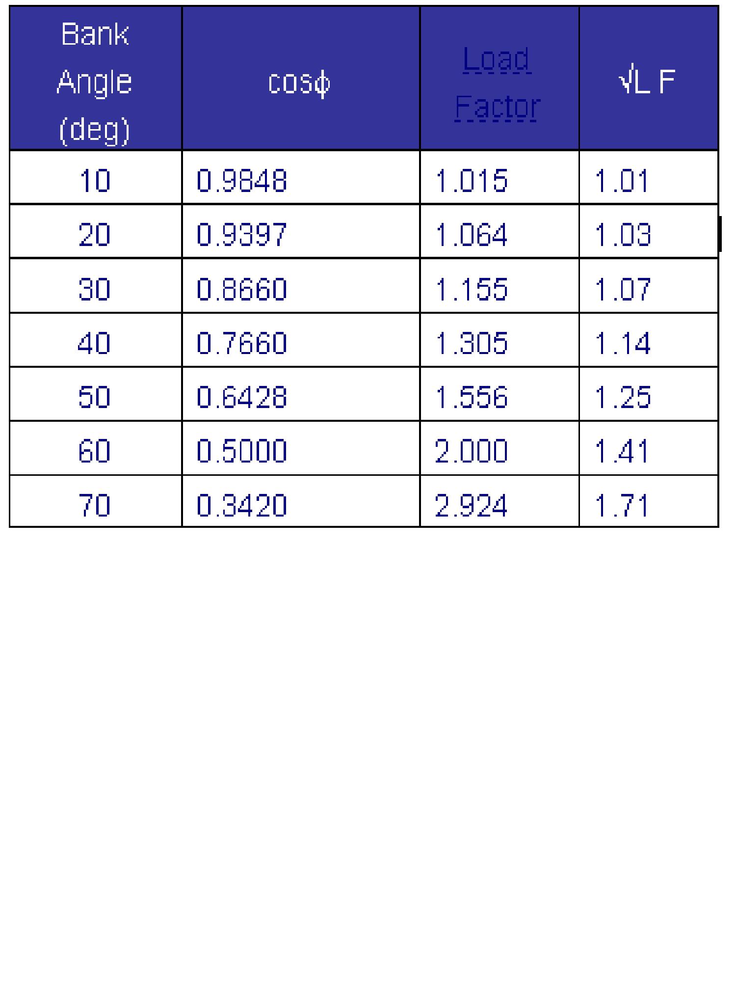
Ridiculous statement. I am sorry mate, but you are totally incorrect now. Turn co-ordinator and turn indicator are used PRIMARILY FOR RATED TURN PURPOSES !!!!! For simplicity sake, this is what the little marks on the face describe. RATED TURNS !!!! Seriously mate, you boggle me sometimes. There are two small equations to work out radius of turn and angle of bank. Radius of turn = TAS/rateX60pie TAS in knots and Rate as Rate1, 2, 3 etc. gives you radius in nautical miles. Alternatively = TAS2 ÷ (g x Tanφ) or Tanφ = TAS2 ÷ (g x Radius) SI units must be used and "g" is the force of gravity (9.81m/s2) From this we can see that TAS has a direct correlation to radius of a turn. Angle of bank (approximation) for rate 1 turns only. = TAS/10+7 If you know anything about flying, angle of bank will mean a reduction in lift, to compensate we need to increase lift therefore increasing load factor. As load factor is respective of G and G is referenced to gravity then anyone who is not a retard will know that a turn will increase G. Its pretty common stuff. For you not to be able to correlate that into my previous arguments shows me you either do not understand or you are deliberately not seeing what i am writing. for added benefit see attached for a table of bank angles and corresponding load factors Again we can see that angle of bank has a direct relation to G loading. Therefore when we are doing a RATE 1 TURN whose angle of bank will be dependant on TAS, we can show that TAS has a direct correlation to a rated turn. I am trying to keep it simple for others to follow, but if you want to bang on about precession trying to discount me then go ahead. I have passed my ATPL's and i can carry anything you want to say regarding gyroscopes. Lets see, the fact that precession works 90 degrees in the direction of rotation. The turn indicator is a rate gyro, with two planes of freedom and one gimbal. It may be air driven or electrically driven. The axis of rotation is in the horizontal plane; the direction of rotation has the top of the gyro moving away from the pilot. When the aircraft is turned the change of direction appears as a yaw rate. This is precessed to act on the top or bottom of the gyro, which rotates in its single gimbal, pivoted on the aircraft fore and aft axis and compresses or extends a spring. When the spring force balances the precessed force the gyro remains tilted away from the aircraft vertical as the instrument yaws with the aircraft. The gimbal moves a needle that indicates the rate of turn I can bang on and bang on about it ...... BUT MATE, YOU REALLY SHOULD KNOW THE OBVIOUS ! Again to bang on about it. You know how a gyro works but you fail to see how it works with respect to an aircraft. I have already proven that TAS in a rated turn will dictate angle of bank and that in turn will dictate load factor and that matey is all the bits you mentioned above that affect the turn indicator as we mentioned above. How can i be wrong. I said and here it is for emphasis "Nowhere in the JAR ATPL theory is the term inclinometer used" JAR ATPL is European and FAA is American. So i was right that it is not mentioned in the european syllabus. The fact you are referencing a slip ball, then i will say slip ball again for simplicity as others can follow.

-
I have posted a track of balanced climbing and descending flight and level balanced turning flight. Please note that due to bursts of sunlight my trackIR was jumping around a bit. But you should be able to follow it ok, just bear with the jumpy bits I have changed the ABRIS to display degrees magnetic to keep in line with compass. You will see that i have highlighted that the compass agrees with the abris direction and we cross reference against track to find the difference between heading (where the nose is pointing) and track (where the aircraft will go) In the climb at the example speed we were only 3-4 degrees off between heading and track In the descent we were only about 2-3 degrees. _LastMissionTrack.trk
-
Yes that is correct, the feature is not implemented. Would you mind kindly putting this feature into my thread "Updates to Black Shark"
-
I am sorry frederf, i think you have misread some of my post and possibly not understand what is meant by a rated turn. A rated turn is also referenced as a rate 1, 2 or 3 turns, most notably rate one turns as they are most common. A rate 1 turn will show show a change of 3 degrees per second. Therefore a rate 1 turn will take 2 minutes for 360 degrees and 1 minute for 180 degrees, no matter what speed you are going. This is what is defined by a rated turn. For simplicity i will use definition of rate 1 turns now to avoid further confusion. Forward velocity will have an impact on the bank angle needed to attain a rate 1 turn. That is why my previous statement was 100% correct. Just to prove to you that I was correct, i will qoute directly from commercial pilot study material. Listed under errors for turn indicators "...the indicators are calibrated to show rates of turn correctly in balanced turns for Rate 1, 2 and 3 turns at specific angles of bank and TAS. Although the indicated rate of turn will be incorrect at speeds away from these datums..." Nowhere in the JAR ATPL theory is the term inclinometer used (well not when i studied for it anyway). however, through a little research, i now know you are referencing the slip ball. If you obtained the term inclinometer from wikipedia then you should not be referencing this material for aeronatuical purposes. For one wikipedia mentions "inclinometer-like". Just to prove a point with wikipedia. Even though it says the author has used FAA material for his article, it has a picture of a turn co-ordinator but it is listed as a turn indicator. However, on the instrument it clearly says turn co-ordinator. LOL Ohh dear. The two instuments are not the same. For simplicity and as the european commercial text does not refer to inclinometers, i will make reference solely to slip ball. Aside from my mis-interpretation of the term inclinometer, what is the point of the above qoute? You are correct, I agree on this.
-
Just for confirmation Jazjar, You can fly wings level, and have the balance ball centered. I have done some indepth testing and as follows. In "wings" level flight with the ball centred and at speeds tested between 210 and 250 klm/hr the difference between track and heading can be minimuzed to about 6 degrees. Here are some some videos or helicopters in flight (both different types) with the ball nicely centred. Volume off for first one. The second shows the ball remaining centered during light manouvres.
-
Easiest way to test it out is to take off at the airport and enter a hover. once in a stable hover uncage the skval. Move the skval over a anything you want to look at and on the left hand console just in front of the engine fuel condition levers are 4 buttons. One is slew to target. Press this and your helicopter should automatically turn to face the direction you are looking with your skval Then move the skval anywhere you like and the helicopter will follow. You can combine this with the helmet mounted sight, and also datalink to automatically slew your nose onto a predesignated target.
-
x52 locks up no pitch/bank then releases...
bogusheadbox replied to lineman55's topic in DCS: Ka-50 Black Shark
I have an X-52 and use the SST programming software. I don't have any of the lockups that you describe. Have you tried looking at the calibration or even recalibrating the X52. Look to see if its spiking or its centre is not aligned. That could prevent the trim system from giving you back control. Have you tried the other trim system incorporated in DCS BS, maybe this will work more to your liking. -
Well for added bump, i will add a few more items that i would like to see rectified - Magtnetic variation dial - Hud tape in nav not showing degrees magnetic. (well if it is, its certainly not corresponding to the magnetic compass nor Abris slaved to degrees magnetic) Is there a problem with the DCS BS or LO2 engine with magnetic variation ? Does DCS hog suffer the same fate ?
-
@ Frederf, You have got the basic idea. However, let me define the two. A turn indicator will show rate of turn however this needs to be established at a given tas and given angle of bank. Usually requiring the use of more than one instrument to perform the task. Away from the set datums of TAS and angle of bank the turn indicator will not correctly show rate of turn. A turn co-ordinator will show you a rate one trun at any given TAS and you can use this instrument solely to perform the task. I am not sure of you term inclinometer and no where through my studies has the term inclinometer been used. Basically the turn co-ordinator has its gimbal raised at the front by 30 degrees which through precession will make it sensitive to roll and yaw. @ Bucic So as i said, they are two different instrument that can show the same information. However, they perform differently, are different and that is why they are not the same. To call them both indicators, well yes, we can in the loose sense of the word call them indicators. Just like i can call an FMS an indicator as it will indicate various parameters of the aircraft for me (if correctly set). I am not after a response from you. However i have replied to the innacuracies you have portrayed. The information you have copied and pasted is correct. The way you described it is not. For the benefit of people who do not know better, i thought it would be good to let them know. In any event and the main point that sparked my discussion is.... The KA-50 does not have either a turn co-ordinator nor a turn indicator where you said it does. I have also clarified the differences between a turn co-ordinator and a turn indicator which you seemed to not know. I have also explained that the balance ball is not a flawed instrument and is quite useful. ----------- Just as an addendum, as it was late last night. I mentioned that the KA-50 only has an ADI with slip ball..... That should read AHI with slip ball.
-
I am not at any point debating whether the KA-50 can do that or not. I am just referring to inferences towards what a turn-co-ordinator, turn indicator and balance ball are, what they are used for and how useful they are. Also i am wondering why these are being referenced as the KA-50 does not have either aside from balance ball
-
First and foremost i am not trying to start a war or a "holier than thou " tug of war. So forgive me if my reply insinuated such. This is incorrect. Both perform differently. A co-ordinator is not an indicator. They can both portray the same information in certain parameters. You can clearly see from the pictures you have posted that they are different designs. Both have advantages over the others. I will let you delve into it a bit more. I do understand that you are referring to the KA-50. However Slug mentioned Asymetric lift and i gave an example of asymetric lift. The same principles apply to rotor as fixed wing in forward flight and hence i used that example to show that you can fly in balance even with asymetric lift. I have no problem with the publications from the FAA that you have posted. I was (and probably being a little finicky) pointing out some misgivings in the way you portrayed that info. Maybe it was the way i read your post perhaps ??? Ok i have read and re-read this part of your post trying to think of all permeatations towards interpretation that i may have missed your meaning. If you are referring to how turn co-ordinators work then..... Flight characteristics will change with respect to pitch and power datums as well as speed changes. For a change in any of these you will need a different input on the controls to maintain balanced flight. A turn co-ordinator will advise you of the INPUTS NEEDED to gain co-ordinated flight level and in the turn. However, if you are referring solely to the the KA-50, then it does not have either a TURN CO-ORDINATOR or TURN INDICATOR so i therefore don't understand why we are mentioning it. Are we discussing how an Turn co-ordinator or indiciator works, or are we talking about the the ADI with slip ball? (though you can work out a co-ordinated turn approx with a bit of mental calc using the ADI and slip ball). I have no problem with you trying to talk down on me. But at what area are you referring to. My knowledge of the black shark that i have utilised since its release or my real life knowledge (professional pilot)? You have not understood the point i was trying to make with my food for thought questions. I totally understand what you have writen, however you do not understand the ball fully. It is not a flawed instrument. It is a callibrated instrument that will show deviations in the flight regimes outside of "balanced flight". If it is not central, you are either 1. Not level in flight 2. Skidding 3. Slipping. This is what it does, it works perfectly. If you choose to fly with the ball not centered, fine, it is telling you that the aicraft is performing one or more of the 3 items above. This does not make it flawed, this makes it useful. Lets face it, a helicopter does what a fixed wing can't. It can move sideways, vertically and backwards. Any compbination of these to the smallest extreme will deviate the ball from centre. Like i said, there if no TURN CO-ORDINATOR or TURN INDICATOR (either of the two instruments in the picture you provided in your previousl post) in the ka-50 so i am unsure why you have referenced it in you post at all. Unless i am a twit and missed this instrument in the cockpit.
-
Not entirely accurate. In a twin engine aircraft, and lets use a prop plane to emphasize. With one engine shut down the thrust of the remaining engine over its wing will cause "asymetric lift". More lift on the wing with the live engine. I can still fly this aircraft in balance (wings level). Depending on the aircraft, angle of attack and amount of thrust used, this can have trade offs. (i can go into more depth here if you would like) For navigation with asymetric thrust (simulated engine failure), we are required to fly balanced, wings level in order to minimize drift that can occur flying out of balance. On a different note, from the first picture, i beleive Bucic may be confusing a turn and slip indicator with a turn co-ordinator. We are mentioning turn co-ordinators and indicators. with respect of the KA-50, unfortunately it has neither. It is only an ADI with slip ball. On the right front panel its a standby ADI with slip ball. There was this statement "You can't tell what control inputs to maintain to achieve reasonably coordinated flight because it all changes dynamically" The first part is not true however the control inputs changing dynamically is. And this IS what the instrument is used for, for you to acurately judge the inputs needed for balanced flight and trim for such. Of course, constant speed and heading changes will necessitate constant different deflections of the controls. Anyway, its all a moot point as the KA-50 does not have either an indicator or co-ordinator. It does have a slip ball and it is there for a reason. And food for thought. The KA-50 has contra rotating blades. therefore does it suffer from large amounts of asymetric lift? Does the KA-50 in reality hover "one skid low" (with bank), is it designed to fly at cruise with bank? My point is, the ball is not a flawed insturment, it is a very useful tool in both asymetric and non asymentric flight (provided you understand how they work)
-
@ Bucic, Sorry i can't agree with your statements of the turn and slip Co-ordinator or "ball". Quite simply this, is a very important piece of equipment. Having the ball centered means you are in co-ordinated flight. I am a professional pilot and some of what you have said is incorrect or misleading at best.
-
You know, that no matter how valid your point may be........... ................. Somethings are better off not said.
-
basically, the X-52 is the best bang for your buck. I love mine