Duckling
-
Posts
606 -
Joined
-
Last visited
Content Type
Profiles
Forums
Events
Everything posted by Duckling
-
Hi Pete A muddigger in disguise in other words :-) how do you manage to get room and time for this beauty ? I recognize most of the stuff on your frame but what are the the HSI and ADI 'stuff' in there, TFT/LCD's or something custom built ? And while I have chanse, a thx.. One of your early pit's and documentation are one of the main reason I was drown into this never ending 'hobby' Those fire-pull handles, where you got them (or did you build'em ?) Gus
-
@Derk, I'm on on Monday evening @Roiegat, great pics (I have a better cam on the to-do list ;-) Anyone have a link (or pic) of a detailed wireframe/'exploded view' of the Huey ? ps. anyone welcome to post info oc. Wish I got some more time for an additional pit. Idea of a three 'seat' Huey pit in a projector 'box' sounds kinda thrilling, and add a 3-DOF base to that (weight would be a main issue though 8) .ds
-
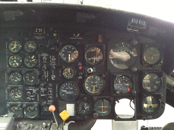
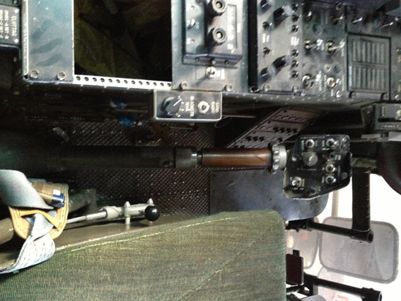
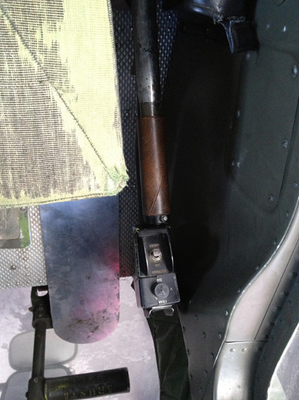
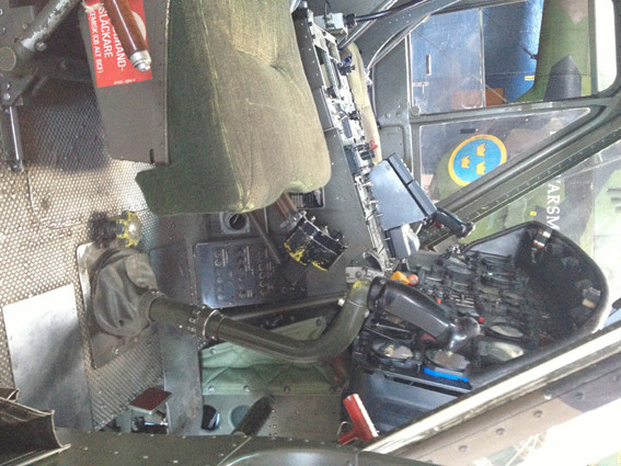
Visited our HKP3B, Agusta-Bell 204B, on the floor at VFM. Pics are less then perfect (as allways ;-) Pics of topside panel was a real disaster.. If anyone want some measurement made from within, write a note here with specs of what, and I'll make it when possible

-
Hi Jrsteensen. No real input but just some ideas I plan to put some additional buttons, switches, rotaries etc on the fuse panel (front lower) to have'em in place for additional needed functions for the future. There's always some that pops up...
-
Search for buildthread by triggerhappy Can't remember what brand of pedals but pretty sure he had posted how to convert to HAL's.
-
How do I sync DCS switches with HELIOS at mission start?
Duckling replied to pitdesigner's topic in Home Cockpits
... sounds a bit a scary, better watch my back from here on ... :megalol: -
A quiz to Gremlin and others here. A bit of topic and is regarding the OCR possibilities used the CMSP export. Could the same type of OCR be made able to check the Magswitch positions on SAS panel, Anti-Skid and AEC/Laste quad ? (in otherwords the position of the 'pin') So far I know there is no way to detect or export the state of these.
-
Sounds great you found the cause Tom. When you connected the 9V power, was that to the Arduino or the LCD ? Just curious since when you had the Arduino connected via USB for power (if I understood it correct), if the Ethershield addon consumed the power needed for the LCD or something like that. On my Arduino specs it states a prefered power of 9V but works of with my VFD using only the USB connection.
-
Bodnar board with the "easy" wiring connector help
Duckling replied to MacFevre's topic in Home Cockpits
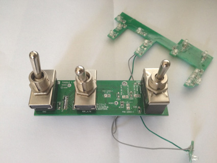
An option is to use a crimptool and pins for the thin wires. We use DB25 extensioncables cut in half (very thin wires) as connectors between different places in the racks. Almost impossible to get a valid connection without the pins and also breaks after a few bends if not secured. Pins that also secure the isolation of the cable is hold securly in place. Pics for illustration only
-
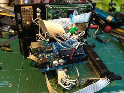
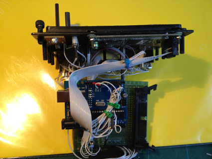
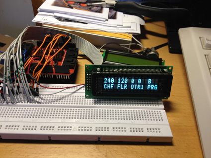
CMSP panel pieced together and now with an Arduino instead of the earlier OC LCD card. Running Gremlins script and with an VFD 16 digit display.
-
My CMSP now together (could be better looking, though ;-) in one piece and working. (COM port still..) A big thanks to Gremmlin, Tacno and also to HMA his code example. A long way for me still but I really hope for a possibility to include the CMSC in the functionallity, or is this already possible ? Cheers Gus
-
Check your export.lua file within the export folder if it's been replaced/overwritten during the upgrade of DCS with a default. Not sure if that's the case but might be a start. There's been some notes here on the forum earlier on how to recover in cases like that And complements to your panels. looks great /Gus (edit... late answer ;-/, Thinks JG14_Smil is correct)
-
Missed the pic in earlier post. sorry
-
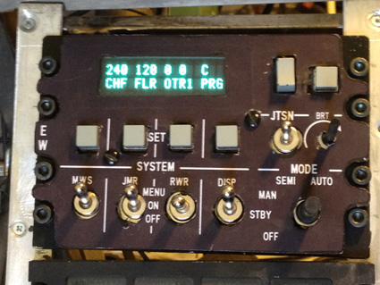
My first err in the setup was the pin assignment within arduino example but I guess you through that. Hang in there Tom. Swapped to a VFD and the brightess in superb. If any still in for the standard LCD, skip that. Standard 100% brightness in the pic, Haven't yet got the scripted dim to work.
-
As an total Arduino noob and also fresh into the cmsp scripts it's not much I could add but only some advice to split the troubleshooting into chunks as..: # Check Arduino vs Display to verify it works. Grab one of the generic LCD scetches within Arduinos Libs, check pinout stated for the LCD (edit as needed) upload and verify you get a 'Hello World' or likewise on the LCD # [edit, removed this bullet, already answered] (geeting a bit sleepy ;-) # the Arduino not showing up on the router, do you get a link ? (The little LED of the routerport says something is connected). If not, you see any short 'blips' on same LED when you connect the ethernet cable from the Arduino ? If link goes active, move to next bullet below If it 'blips' you might have the router port hard set to a speed/flowcontroll not supported by the Arduino ethershield if nothing, verify the Ethershield, Arduino LIBs etc (can't help you there, sorry) # Run a CMD Window and make a 'ping <arduino IP address> and see if you get an answer if not, check thatyour PC is on the same subnet (Command window and 'ipconfig' ) Chousen IP address of your Arduino should be in the same 'subnet' as the PC and use same mask. If your PC is for example on 192.168.0.x and you have a standard mask (say 255.255.255.0) it wount reach a 192.168.1.x etc. (Also verify that your chousen Arduino IP address is free and outside any DHCP scoop defined in your router etc, Firewall settings on your PC might block to the address or port of the Aurduino etc (but std settings is to allow all outgoing traffic but one never knows) Not ventured yet in the cmsp tool IP setup so I'm lost there but as Hans says the target Arduino IP must be defined within there Cheers Gus
-
made this for Rocketeer some time back. Not sure if same knob apply for all versions of the TACAN though
-
Hi Tom. I'm getting low on USB connections (allmost all ports on backside of PC is filled and I'm using 2 powered hubs already). EtherNet connections will leverage the possibilities and the cost is lower then an additional HUB. Second reason is it's fun :-)
-
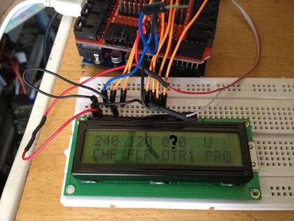
Hehe. It works (ofcouse) :-) :thumbup: Thanks Gremlin and HMA for the added eth exampel. Here only with Com version and a standard LCD (an Ethershield + VFD will be next step) - Missed a character when edited the inputs, the "0" top row marked with an '?', marked in the pic attached. Is there a way to edit just a specific character position or is it faster to redo the complete process ? Cheers Gus
-
If glue is not an option it's a small bolt trough the lightplate/base (and pcb's to be removed prior) or a special made 'tube' (say Alu 1mm+ with inside thread (same as switch outer) with a cap topside. The PVC 'hole' round the EAC switch could be widened a bit to get the tube in ontop the switch. Maybe far off the topic here :-) Or.. remove the Laste lightpanel/faceplate. Its fairly thin, 1.8 mm. Drill a small hole throuh the switch baseplate and the lightpanel, use a M1-M2 small bolt with countersinked head, (not sure it's the correct word here) from underneath and up through the flip-cap base and a nut topside. Then put the all chabang back in place. A Dremmel (likewise to remove enough material under screwhead is another option.) Superglue would be my first option though, with some aditional cleaning before applying I think it would hold. The lighpanel on the TM feels a bit fraguile. But I'd recommend to skip the flipcap. Normal position is in ARM position and a selfmade look-alike real guard plate will add a bit of autentecy and can be held in place with the little screw seen below right of the switch in your pic above. Just some ideas from top of my head Just checked my store. Still got the TM Laste faceplate on the shelf. Drop me a PM with your address and I snailmail it to you if interested. I got no use of it (cut the hole LASTE part off my throttle). Easier to experiment on something like it.
-
Not sure what type of 'cover' you got, If it's 'flip-cap' like as on the KY58 and 'GroundArm' switch I'd avoid use it, both from operational side and for how to secure it to the Lastepanel. Superglue might be an option through. Topside of switches doesn't raise above the lightpanel enough to secure the plate of the 'flip-cap' enough. You got 'some' free space below the lightpanel of TM 'Laste' switches that in turn is on a separate PCB (se pics). If making an more realistic cover it's a metal plate with side bent upwards left/right of the switch and would be easier to make and get into place. If you want to make some additional 'holes' to secure whatever cover you plan to use and risk void the warranty on the TM throttle, you can remove the PCB for the switches and LEDs from the bottomside of the throttle, just be very gentle with the wiring connections, they split easily (don't ask how I know ;-) (the thin 'lightplate' topside of the Lastepanel is glued on the base and could be removed with a thin flat screwdriver or likewise)
-
Excellent and impressive, frank :thumbup:
-
Might be a longshoot but this company http://www.aluscreen.se/tjanster/tangentbord is located near my office (Sweden). Can't tell about prices on keytops etc but they helped me out cutting Alu some times. They produce a larger number of products, they fast and serviceminded. English shouldn't be a problem but if you need a translator send me a PM with info and I could pop'in next time passing by.
-
Hi DM. PM sent. Please ping me back if not recieved
-
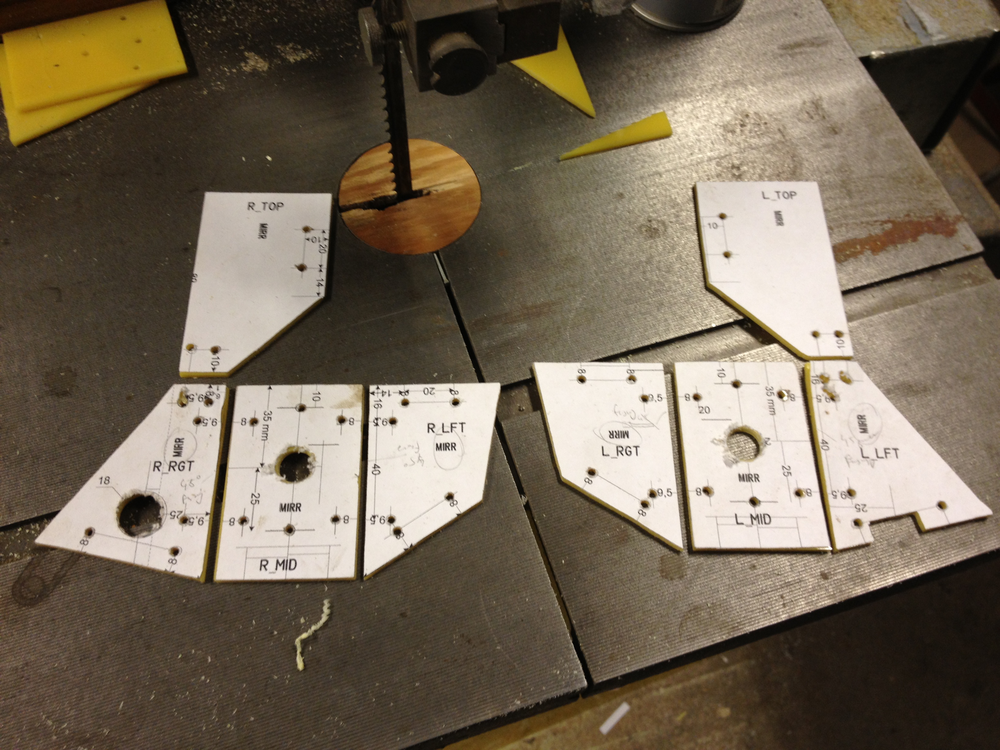
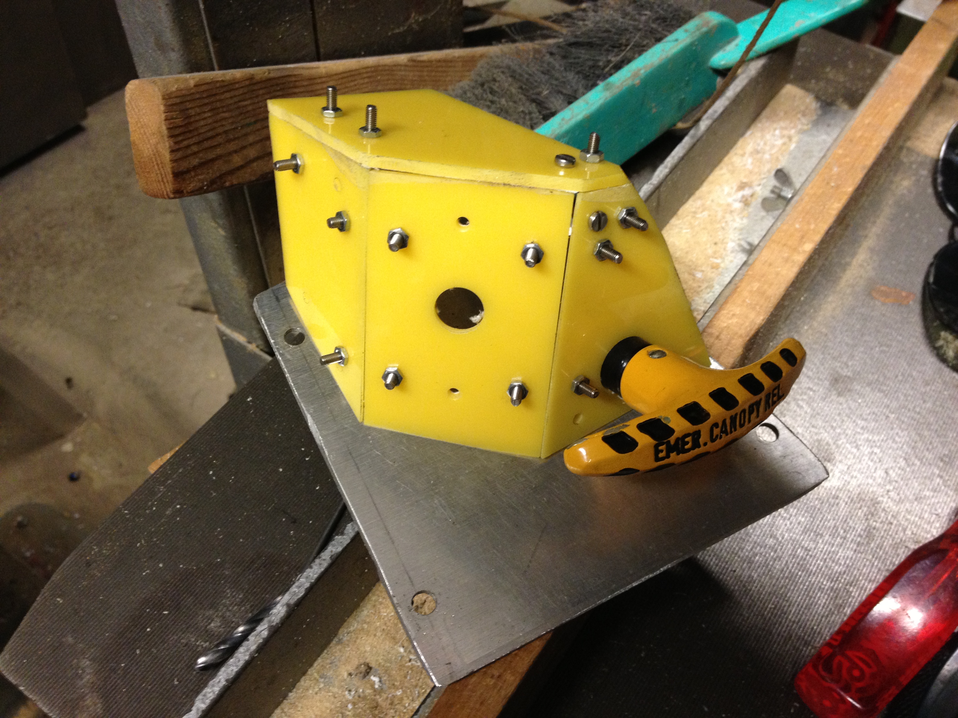
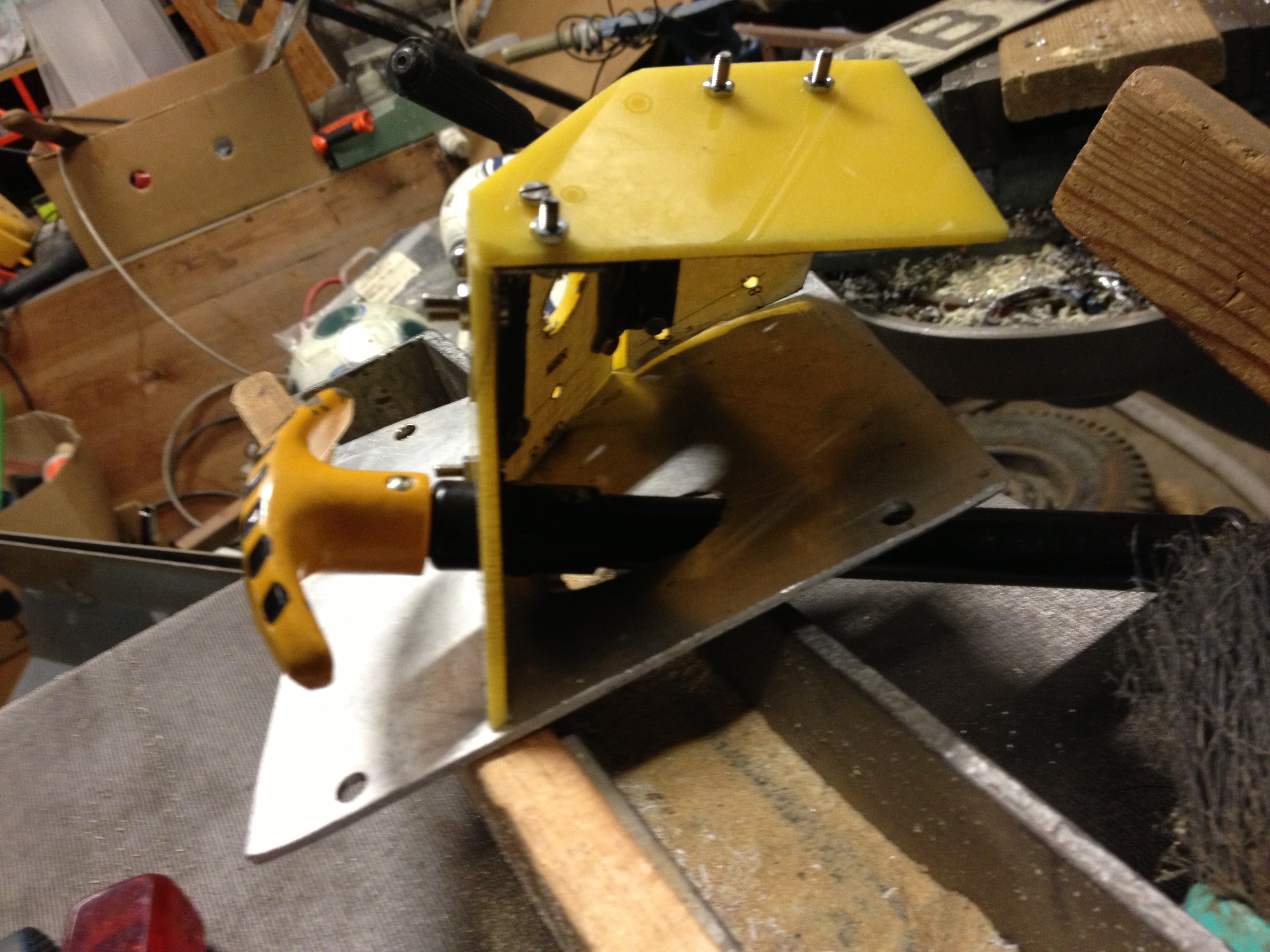
Started with the outer topmost quads on the the left'n right panels. Those angles are a challange :-) but I managed to get it somewhat near the intended position... still some way to go but rather pleased with the result so far (Should been made with Alu but was out of material and found sheet of Acryl.)
-
So... at last I got TACAN quad to work with SIOC. Credits goes to Oakes and Jockman and several others for building the codes to export data into SIOC Answer been 'here' since 2011 but I didn't grasp the context uptil now. Metal and Gadroc also stated what's needed to be done but I'm a true slow learner ;-) Thx guys :pilotfly: Quiz been how to handle the relative values AND negative inputs to clickabledata.lua via SIOC controlled by an encoder output Been stuck in the first part so long with with try'n errors efforts I'd almost given up hope of ever understand it but here it is if any other have the same issue Some garbage in the code below (as usual, but please ignore) Success came when allowing negative values in the SIOC_parse function AND used native encoder output, i.e toggling 0,1 and 0,-1 depending on CW/CCW rotation [Note: SIOC Version 4.0.1, DCS v1.1.1.1, DCS, Helios and SIOC combined with Oakes scripts.] Export from mainpanel_init.lua of the frequency of each digit + X/Y value to SIOC and parsed into a 7-segment display digit (with top and bottom segment disabled) '4' as 'Y' and an 'H' (digit 8 ) Encoder code to set the values from SiocExport.lua: From SiocConfig.lua (subset): hogbox.ssi ("aka *.ssi" from text export): ExportSupport.lua Cheers Gus