Duckling
-
Posts
606 -
Joined
-
Last visited
Content Type
Profiles
Forums
Events
Everything posted by Duckling
-
How to mod a TM RS system (QnD warning..)
Duckling replied to Duckling's topic in PC Hardware and Related Software
Rudder somewhat ok, been unused for long time and sure needs some grease/lubricaction. Adding the "steps" was a good move. Original pedals setup needed more force downwards, to be moved forward causing a quirky movement.. Pedal break axis is ok, has a small gap still in the hole where the pot flange is seated, less then 1mm to be eliminated but axis move of the pedals is smouth. Only rudder connected to sim right now, haven't found an option to use anything else then on/off setting in dcs for wheelbreaks, thinking of connecting break pots to OC card to use sioc to trim/control when to activate the "breake-on", or add a pushbutton beneath each pedal. Anyone knows if there is some "easy" way to trigger the brake function based on value/position of an axis ? -
As said in the title. It's real quick n dirty label attached here :-) Had an old RS system (No wheel breaks) with a bad center pot that needed replacement. Descided to give it a try to add wheel break pots, replace the center (L/R pot), modify the pedal "plates" and raise them from floor aprox 5 cm's http://www.strandedduckling.com/TMRS_MOD1.jpg http://www.strandedduckling.com/TMRS_MOD2.jpg http://www.strandedduckling.com/TMRS_MOD5.jpg http://www.strandedduckling.com/TMRS_MOD6.jpg http://www.strandedduckling.com/TMRS_MOD8.jpg http://www.strandedduckling.com/TMRS_MOD11.jpg http://www.strandedduckling.com/TMRS_MOD16.jpg http://www.strandedduckling.com/TMRS_MOD22.jpg http://www.strandedduckling.com/TMRS_MOD25.jpg http://www.strandedduckling.com/TMRS_MOD26.jpg Some more info and pics here: http://www.strandedduckling.com/html/pedals.html Cheers Gus
-
Hi Niclas. Board soldered and tested (only some A/D ports so far) Works great Thanks /Gus
-
Great work Gadroc, Thanks for the build thread, great reference, will save a load of time.
-
Great find, DM :thumbup: Can you check and post the aprox dimensions ? Would be great to able to make a "look-alike" copy /Gus

-
Hi R1 No problem at all :-). Just check if the size of these are what you looking for. They are bigger then the original. It was the smallest size I could easily get hold of but still pretty high. I got these from ELFA 75-506-92, Everlight ELS-315GWA (Green). Just checked and ELFA stat'em as discontinued. https://www.elfa.se/elfa3~se_sv/elfa/init.do?item=75-506-92&toc=0 If you find em somwhere and want to use'em, the EagleCAD file for the PCB is attached (.zip) below. I made a misstake in first run that is corrected in the attached post. It's a one side board (the wiring that is :-) A few homemade patches is needed both to enable one of the 7segm units and also for the decimalpoint. It's a real "quick and dirty" job but might be usefull. Baseplate is far from exact and a few parts has been widened. (Note that the PCB is made for Common Cathod type of 7 segments) Ping again if questions or clarification if needed Cheers Gus HOGBOX_COMPanMain_v1.1.pdf Visio-L10_COMM_v0.5.5_subsection.pdf HOGBOX_COMPanMain_v1.1.zip
-
Sure does. Great work on the CDU and caution panel :thumbup:
-
Can anyone recommend me an USB connectable board that handles many A/D converters ? And can use LUA in some way ? -- Edit: Got one of Brydlings boards (13 A/D ports), that was intentially planned for other purpose... Will redirect it to here and try it out.--- Got at least 25 pots on the left/right panels outside the scoop of available ports on my existing Opencockpits USB expansion cards (THAT was a too long sentence ;-) (There is an option on the Mastercards that uses 8 digital ports per pot but the expense total goes to high) and portcount alone is beyond the available limits Thanks Gus
-
Thanks guys. Far from finnsihed but it's a great feeling just to try out the startup sequence and find (allmost) all things working. Caution light pops up in correct sequence etc :-) Found out another nice thing, -A model differs from -C model on the Caution panel text, LOL, so back to Visio (in my case) again. Cheers Gus
-
Thanks Linden. The two Red is sold. PM recieved. One from me inbound soon Thanks Gus
-
Hi Lancer. some input (but remember that I'm far as skilled as Oakes and several others here, so I might be getting this wrong, LOL) Have something of the same situation myself where sometime I have to activate a switch twice before anything happends. You can (If I understood things correct) use either SIOC Var "0" to initilize VARs at SIOC start or use LUA to trigger the same thing. When SIOC starts, If not mitigated all Vars are uninitialized, i.e. regardless of what the switches position are, their position is unknown seen from the SIM. When you activate'em, their values in SIOC will respond accordingly but it's also dependent on how you connected em and coded their values that going into SIOC. If recycle the DCS while having the SIOC started, SIOC Var's will still have an active state in the "database" of the last known value/position (at least I think ;-) I haven't ventured into this due to time and effort so far. Also interested in a more clear description of the case so anyone up to it please correct me and/or fill in the blanks Cheers Gus
-
Finally got the extension cables to connect existing mastercards to the USB expansion boards on both left and rightside panels. All quads in place now connected and interfaced (not OXY of obvious reasons, need a small trigger in place first) but some still missing as you can see as the CDU (don't forget me now y2kiah :-) , the outer topside quads (I hate all these angles :devil_2:, I never get these correct but still trying) and the fillers on the rear both sides. Rest of the switches works but a few mentioned glitches and the ILS/TACAN 7-segm displys to where an extra card just been ordered. What you think of my "ACESII" chair ? Wify suggested a rocking chair instead. Would surve me better according to estimated timespan to when this rig will be finnished (if ever) Some pics of the cabling mess from underneath the rightside panel. (ignore the rust stains on the pics above, it's proof of old age and will be taken care of when paintjob starts, will not say when though :-) Cheers Gus
-
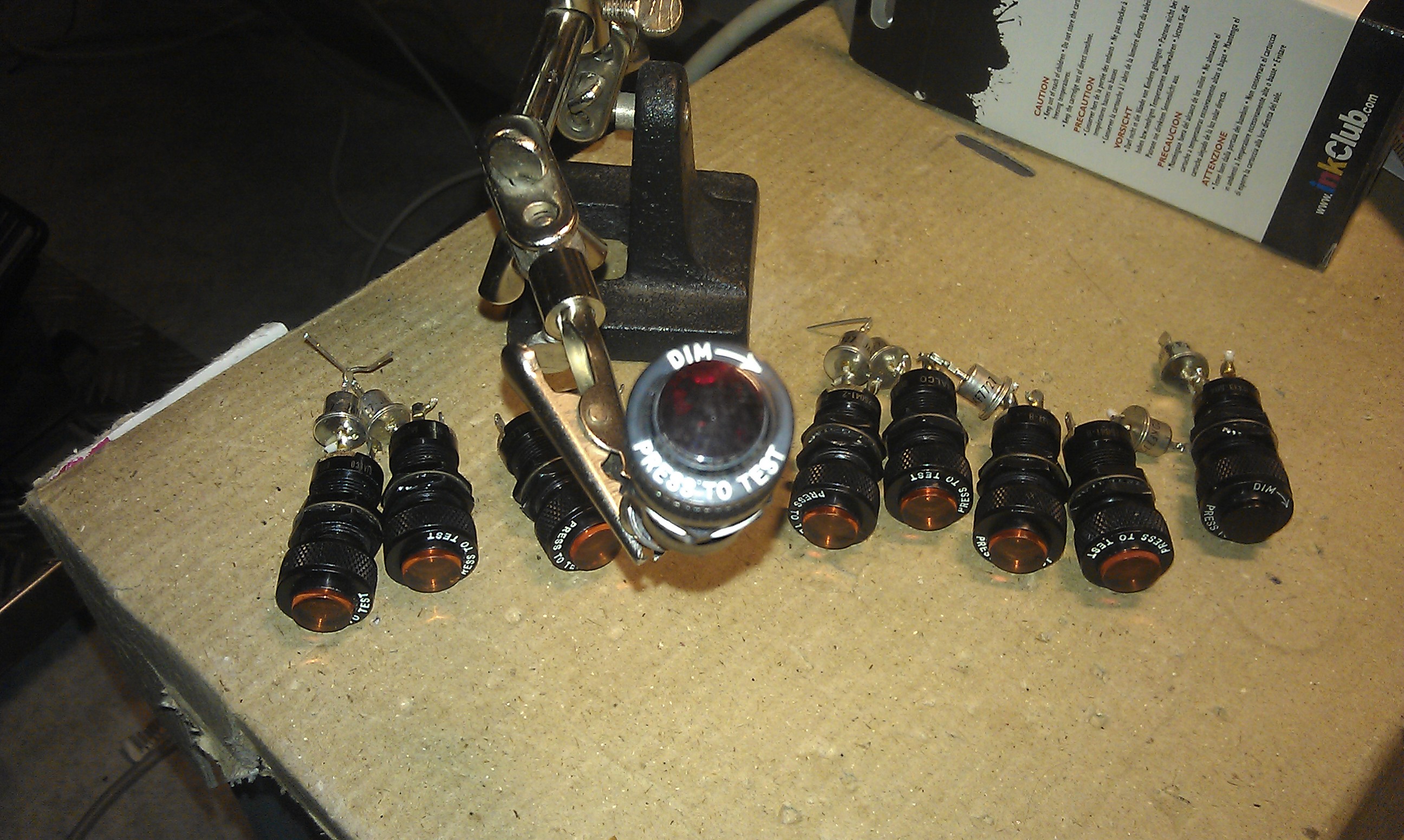
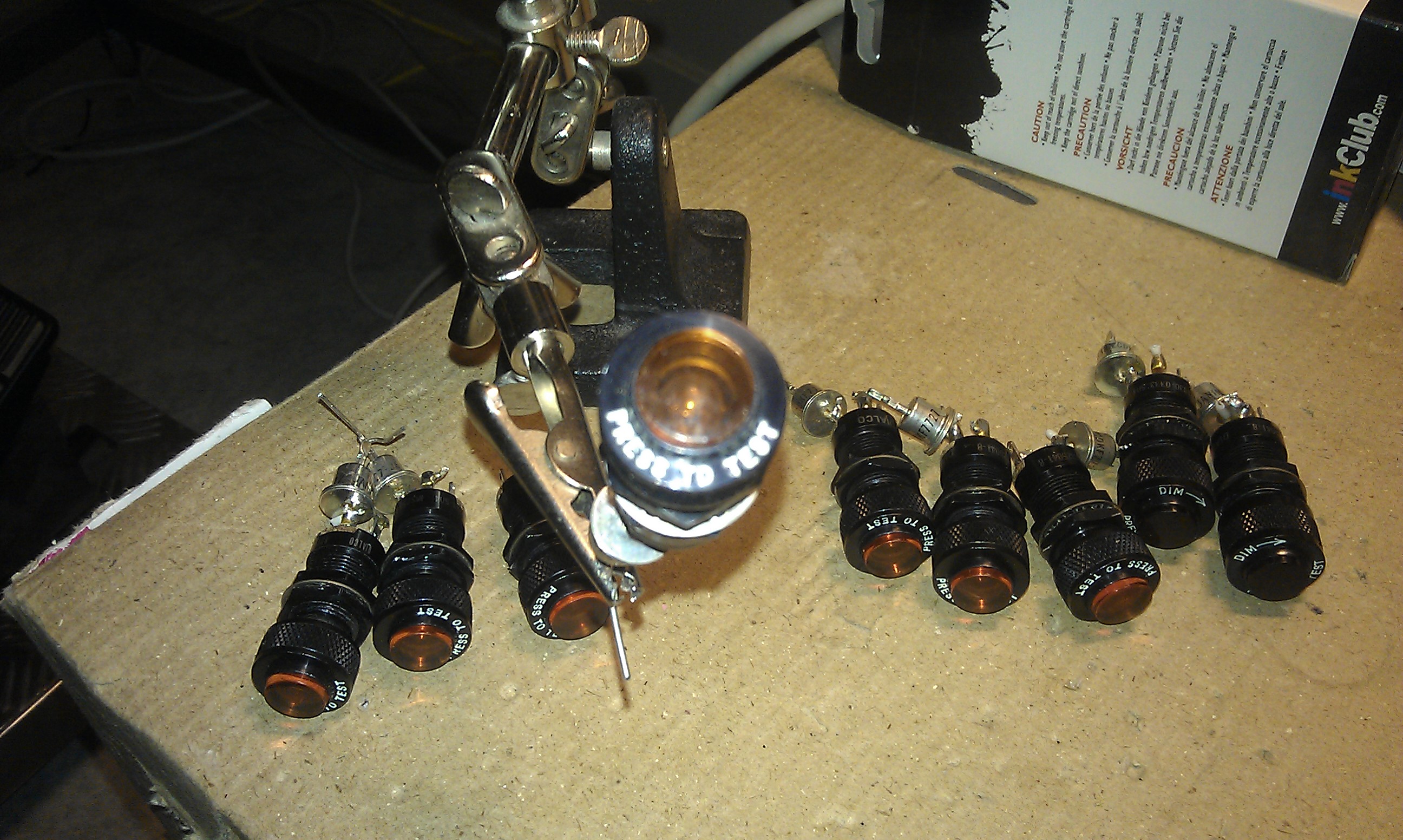
Yupp. you guessed correct, wify been ordering me to clear out some space in the closet, (I have to come out sometime, don't I ? .. kidding) These indicators has same size as those on the A-10 IFF panel (but these are Orange and Red. not green as on the Hog !!) Might still be interesting though ? Panel mount hole, 12 mm Outside "knob" 16 mm Bulbs tested with Ohm-meter working, probably 26-28 Volts but I can't say for sure Got: SOLD --< 2 x RED, PRESS-TO-TEST with "DIM-->" --> SOLD Remaining: 7 x Orange/Yellow, PRESS-TO-TEST. DIALCO "800-1030-0333-504" / "MS25041-8" Bought these from Germany many years ago so I wount ship'em outside EU Requesting 8 Euro/piece + shipping, paypal only All additional costs incl taxes, pp fee, etc in on the buyer Ping me if interested Cheers
-
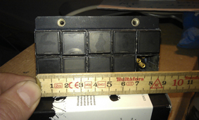
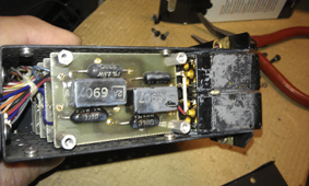
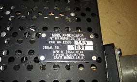
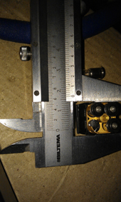
(No not the DCS-10 !! its the DC-10 http://www.airplane-pictures.net/type.php?p=92 ;-) At least DC-10 if I recall correct from the early days when I started building my Rig. Only indicators so what does it do here ? Well, each individual indicator has very close the same frontside measurements as the A-10C Navigation Mode Select Panel (NMSP) squere pushbuttons. Outside dims of the Annunciator is 17mm (house) and the light itself 16,4 x 16,4 mm. 4 bulbs each with a marking: "GE327". Note that it has 9, (out of 10), Annunciators so one is missing. Bulb diameter (not including the flenge bottom) is 6 mm so 12 Volts equivelent or LED should be possible to find) Operational state is unknown and for simulator use only. Requesting 80 Euros + shipping (worldwide), paypal only Weight .5 kg , size 6*9*15 total excl package. Ping if interested and I check for shippingcost All additional costs inch taxes pp fee etc in on the buyer Cheers Gus
-
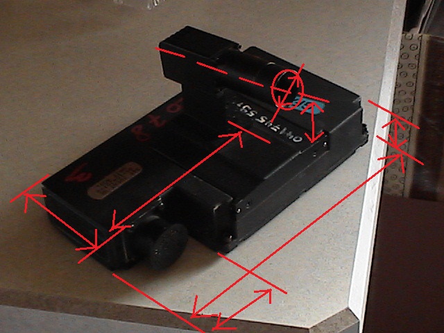
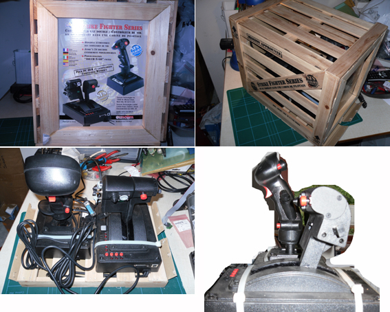
Most of you probably aware of what this is but just in case, it's a gameport connected device. Not an USB. Location is -->> Sweden <<--, verify shippingcost if international buyer or please ask. Been on the shelf since I bought it several years ago from a fellow forum member here and I have never connected/used it. (It was pre TM WH days :-) Mint condition in original packing, very hard to find. It has original wodden emballage and size 35*28*28 cm, total weight aprox 4 kg. Lacks manual and sw but you find more info within the public links below. Can't say if a Gameport to USB converter works but most converts these using X-Keys, Leos cards or likewise. Brydlings cards probably would work also but I can't say. http://calltheball.enjin.com/forums/m/313473/viewthread/143169-suncom-f15e-talon-sfs-throttle http://www.f-15e.info/joomla/en/technology/cockpit/81-pilot-throttle http://www.f-15e.info/technology/cockpit/forward_stick/forward_stick.htm http://www.amazon.com/Manhattan-Usb-Game-Port-Adapter/dp/B0009PXKZ8 http://www.computerpartner.no/Suncom/Suncom_throttle_teknisk.htm http://www.combatsim.com/archive/htm/htm_arc4/sunthr.htm http://simhq.com/forum/ubbthreads.php/topics/2497386/3.html Shipping within Sweden is 90:- SEK via Schenker International / Europe is aprox 43 Euro (or 35 GBP) via Swedish Post office (I know it's expensive, but that's out of my control ;-/ Requesting 100 Euro and paypal payment only. All additional costs including taxes, shippment, pp-fees etc in on the buyer. Cheers Gus
-
Thanks R1. No servos yet. Just now reached the quads where to add these. Have to decline the teaching role though :) Far from skilled enough. Cheers Gus
-
One step further though on the UHF Freq dials. As expected, the answer was right under my nose, LOL By Using SIOC "LIMIT" instead of "ROTATE" function, it works ok (at least so far ;-) What I still can't figure out is how to to trigger left OR right mouseclick-action based on the encoder output. Most greatfull if anyone that can show me how to solve this quiz ? My coding skill sucks ;-/ As an example: The VHF Channel select wheel Var 0651, name VHFFM_CH_act // VHFFM_PRESET_CHANNEL_SELECTOR Var 0677, name VHFFM_CH_PRE, Link IOCARD_ENCODER, Input 57, Aceleration 1, Type 2 // PTR-ANARC186-VHFFM-PRESET_input { L0 = &VHFFM_CH_PRE &VHFFM_CH_act = ROTATE 0 ,19 ,L0 &VHFFM_DSP_CH = &VHFFM_CH_act + 1 (ignore this line, its the value parsed to the 7 segm disply) } Having the following in SiocSupport.LUA: [651] = {VHF_CH_Select, 56, 1, 2, -0.01, 0.01}, -- PTR-ANARC186-VHFFM-PRESET i.e I need to get a value from SIOC that state if the last movement of the encoder was clockwise or counter clockwise. Problem is (I think) that the pValue sent is absolute instead without directional info So I could make something like this in exportsupport.lua: -- VHF_CHANNEL_SELECT function VHF_CH_Select(pValue, pDevice, pNumber1, pNumber2, pType1, pType2) local pVal, pNumb, pType if pValue < 0 then pNumb = pNumber1 pVal = pType1 elseif pValue > 0 then pNumb = pNumber2 pVal = pType2 end GetDevice(pDevice):performClickableAction(pNumb + 3000,(pVal * pValue)) end or.. GetDevice(pDevice):performClickableAction(pNumb + 3000,(pVal * (math.abs(pValue))) Tried (with best effort and failed) to use an extra SIOC Var that was updated with the last selected channel to compare the next value from &VHFFM_CH_act, and assign a negative (leftclick) or positive value to the pValue. Code for those attempts not shown here though Cheers Gus
-
Hi R1. I use Oakes script as base, and the "275" is the SIOC Variable number. The line is siocsupport.lua [275] = .. 38,13.. and the actual value from SIOC is calculated within the exportsupport.lua function so in the end, the device ID 3813 with the value is what is used. # Tested using an Encoder for YAW Trim(same LUA function used as in earlier replay above). It works but problem is the encoders resolution per full turn. To get the hole span of 256 degrees (in example below) one needs to turn the encoders many times the full circle. Splitted it up in 5 steps increments to limit the physical movment of the nob itself and still needs to make allmost a full circle and not granular enough. On the other hand using a "round" knob or ignore the position of the pointer on the knob it still usable skipping the 5 incr below. Added a "push to synch" to center the setting. Var 0700, name SAS_YAWTEMP, Link IOCARD_ENCODER, Device 1, Input 39, Aceleration 1, Type 2 // TEMP TEST { L0 = &SAS_YAWTEMP * -5 &SAS_YAWT_act = LIMIT 0 ,255 ,L0 } Var 0701, name SAS_YAWT_act, Value 127 // temp Var 0702, name YAW_SYNCH_tmp, Link IOCARD_SW, Device 1, Input 41, Type I // YAW_SYNC_TEMP { &SAS_YAWT_act = 127 }
-
Hi R1 This works for me: (A 10k pot connected to one of the analog ports on the first USB expansion card) in SiocConfig LUA: [275] = {TruePotentiometer, 38, 13, 0.1}, -- PTR-SASP-YAW-INC In the .ssi file: Var 0275, name SAS_YAW_TRM, Link IOCARD_ANALOGIC, Input 1, PosL 0, PosC 127, PosR 255 // PTR-SASP-YAW-TRIM in ExportSupport.lua: function TruePotentiometer(pValue, pDevice, pNumber) GetDevice(pDevice):performClickableAction(pNumber + 3000,((pValue -127) /127)) end
-
Looks realy nice Linden.
-
Great result on the cab pres gauge DM. It sure looks brand new.
-
Thanks for clarifing y2kiah. I checking for options to enclose my rig in the future. Both for the look and feel, also in a way to protect the panels. Currently I "step inside" and a misstake might end up crack the panels while enter the Pit. When the seat is added, the danger is worse. Building a shell both light and sturdy enough with a short ladder onto it will be a nice looking insurance.
-
Thanks Linden. Incredible fast reply I'm 70 mm to "low" in my rig but on the other hand, there is space to grow, hehe
-
Linden. looking great (ofcouse :-) A quiz: from the setup you made. What is the height from floor to topside of the "panels" mount ? (mao. från golvet upp till toppen av "plattan" där panelarna ska på ?. Grunnar på att använda enbart "ytterhöljet" att kapsla in mitt befintliga bygge) /gus
-
Great if you can share some pics of the process if possible. i.e. where and how you attach the stepper and sensor and other modifications needed. Haven't yet gutted my VVI so it would save me a lot of tinkering :) Best Gus