ward8124
-
Posts
181 -
Joined
-
Last visited
Content Type
Profiles
Forums
Events
Everything posted by ward8124
-
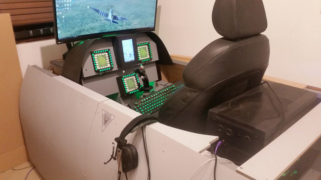
Hey all, I've been reticent posting pics of my pit on here due to the high calibre of workmanship I've witnessed from many of the members pits and didn’t want the purists/smiths to ridicule my handy work. However I've decided to do so just to give others inspiration to give it a go as I am far from a tradesman/wood/metal smith/Engineer what ever and I've done my first major pit. I'll start from the beginning which was to get a bunch of "Must have" requirements and objectives for the pit. These are/were: Must be ergonomic for long stints and comfort Must allow ease of access to get in/out and to the PC/Peripherals Must be VR friendly Must be loosely based on the FA18 cockpit as this is THE module I am most looking forward to (Among others) Design must be modular and be able to be assembled/disassembled easily Must be future proofed - i.e. front panel to be removable/changeable Must be able to allow adjustment of HOTAS/Stick Must allow for UFC and CDU panels for A10 and FA18 I've spend many hours looking at forum members' builds, designs as well as some of the 9th Shrek Squadrons pits and picked out pieces from them all and mashed them together in a design in my head. So I started just before Christmas with some rough sketches and mucking about with some old cardboard to get a sense of size, fitting angles etc before I dived balls deep in to manufacture from MDF. "Design" Front structure I spend ages upon ages looking at other designs in detail and looking to and from pictures on google images of the FA hornet pit. Somewhere along the way I kinda blurred all the different aspects of the images into a single design as I’m not aiming for 100% accurate 1:1 functionality but more towards getting a good look and feel as an FA18 hornet would give me but also to chose function over form i.e. the ergonomics of how it will feel for long missions and VR I cut out cardboard templates to start with and sat in my existing chair to see what would feel right and eventually got some measurements to work with. I kinda skipped the refinement and planning stage and went straight to “FCUK it!” I’ll build it and figure the rest of the shizzle out as I go….this came back to haunt me on a few later points however….. So I invested in a router and did a bunch of youtubing to see how the flipping thing works and what the tips are for getting templates all the same, decent finish and relatively symmetrical. I did quite a few practice runs and screwed up a whole load of mdf to scrap but learnt the lessons and eventually started to get the knack for it. The problem wasn’t my execution of the router but making sure the measurements and things were square in the first place which I agonised, measured, remeasured and still managed to muck it up on a few occassions. Good job MDF is relatively cheap…...ish. Templates - Front panel Panel support structure Base Front Structure Assembled Panel extension to ground to mount warthog stick plus center MFD mounted on hinge for adjustment later The next bit I manufactured was the trolley system for the front and rear fuselage to separate allowing me access to the seat nice and easy. I didn’t get a photo of this for some reason unless I’ve deleted so if I find it I’ll post it but it’s basically a piece of flat 18mm MDF with a slot cut out and 4 rubber 100mm castors attached. I then fitted guide rails for the castors to run along and maintain position. My next problem was space as I now wanted to work on the surrounding structures and my garage being full with an R1, Vespa and assorted tools and benches did not allow me a lot of room to operate! So I dissabled the base, front panel and support structure and prepared the man cave in which it would live. So the first this I had to do was take down the old “pit” and re-use the wood from that for later on in the build With that done, I spend a long time getting the seating position right and then figuring out how high I wanted the throttles and sides. Again, I used boxes/cardboard and wood to get to a position I felt comfortable with and then measured up. In hindsight I should have spent longer here as I’d miscalculated the angles I wanted as well the final height of where the panels will sit but the end result is not too bad and there is room for modification in the future so not the end of the world. Once I’d got the heights I needed I then reverted to the trusty old cardboard and drew out the shape I’d need or want. Getting the right curve was a PITA but eventually I settled on one and then proceeded to make a template using a jigsaw and 12mm MDF. Once the template was done I ordered a shiz load of MDF precut to certain sizes and the use the Router to exccess til I’d got enough struts for both sides front and back. It was here that a few things kinda went wrong with initial design choices i.e. I wanted the PC at the front to connect to. Problem was that I’ve a mahoosive case (Betfenix colossus) which would not fit under the struts unless I carved a large portion out. So I did but this ended up being a PITA as I’d forgotten the need to run support wood through and now I didn’t have this. I ended up creating a new small internal structure for the front left surface to put the HOTAS throttle on. It worked but I was still a bit unhappy with it. You can see it here just about in the corner where I’ve hacked away the templated strut This decision came back to haunt me as it set of a chain of events and bodges which I did to the left side of the pit which need not have happened had I thought it through better. The left hand side ended up a little wonky and needed supports to even it out as you'll see in the pics later. So anyway things were coming together and it was starting to look more and more like a pit and I spent a lot of time gluing wood together and attempting to get things straight which was hard as the floor itself was at an angle which is far from ideal. I persevered non the less thinking I had options to adjust at the end. The next phase I needed to do was fixing the rear structure to the trolly mechanism so that it would move with it to the rear. Again another thing that in hindsight demanded a bit more attention as I'd not manufactured enough support for the weight and as a consequence the sides were rubbing against the base and causing friction. I eventually overcame this by putting struts across the two rear sections so they remained rigid and kept the sides from rubbing. Here's the pre-strut implementation The more observant amongst you will see that there are inaccuracies with the levels of the platforms and the angles are not as steep as they should be. This is down to uneven floors but some hasty workmanship in terms of measuring and design. I intend to modify these in future and get a much more accurate fitting but for now these will do as by now my wife is giving me an ear ache for the amount of time I've spent mulling over and banging away at this pit so far. At this stage I'd completed the right handside of the fuselage and was much happier with the workmanship and simplicity than the left hand side. The PC position was still eating my insides and gnawing at my soul to the point where I lost my temper with it one day when trying to move it in and out between the struts. I was a no go and would not move unless deconstruction of the struts was done and looking in to the future, I could see me getting mightily peed off with this and so made the decision to move it. Having looked at the rear of the pit I could see an obvious candidate in which to place it. However this also introduced some more challenges as it would make the rear heavy and so when the trolly passed a certain tipping point it would dig in to the carpet and go no further. The solution was cut out the unused base section and fit wheels under the trolley to stabilise it at full extension. Another issue I now had to find a solution to was the fact that just about all my peripherals now needed to be connected somehow to the PC but the cables would not be long enough as they were. To get around this I used a long quality USB3 (5 meters) and a USB3 hub situated on the left side where all the cables can connect to as well as take advantage of the inbuild USB hub on the Acer Predator screen to increase the number of USB ports I needed. I also required to get a 5 meter displayport2 cable to run from the back to the front. As the structure is moveable I didn't want cables getting trapped or damaged so came up with an idea to use an old metal table leg which is hollow and routed it through the ends of the fuselages so that the cables don't actually move and there is enough play from the excess cable to handle the extension. The last bit of this phase was just thinking about the cooling of the PC as it is snug to the sides. I cut out holes to the front and back to allow airflow. Later I'll be fitting fans for extraction and cool air flow and exhaust system. Next up was the chair. The chair is car seat out of an Audi S4 S-line but I needed the joystick between my legs and as things were, the front of the seat would not allow this. I then took a hammer and a hacksaw and dissasembled the front, sides and bottom as there was an offset from center that needed to be dealt with. I then cut out the front knee support and glued/secured/bolted the knee/thigh supports back to the main seat chassis which did the trick just nicely. I think in future I'll build a seat from scratch using MDF but I'd just spent money on the chair and wanted to get some use out of it first not to mention that it's a damn comfy seat. Seat to the right with cut out section I now needed to come with an adjustable height joystick mount so again, I reverted to using a metal table leg, cutting a 33mm hole in the centre mount and then securing it. Nice and simple tight and very little wobble. At this point I decided to paint the internal fuselage with "Battleship Grey" colour from VALSPAR as it was interior wood and finished in matte not to mention it doesn't need priming either. Looks quite nice IMHO. You'll see that I put a hardboard 5mm across the top of the panel to simulate the cowel/cover/sunshield from the FA18 and used applied force/tension to bend it to shape using some of my weights. Did the job nicely. Also made a start on covering the insides of the struts too. The project at this point had been going for a couple of month as I'd had Xmas to deal with and had to take enforced breaks away from fettling with the pit courtesy of the wife and child. Patience was also running low as I was missing air time in the new releases of Spitfire, Elite Dangerous and so on and so I made the final push to get things working and useable. I connected up all peripherals and routed cables etc, got the screen a new mount to extend the height and the built a housing for the lillput touch screen to act as a UFC/Panel etc. Cracked all that out and painted but then it came to the skinning and this took me some time due to measuring/bending boards as well taking apart the whole pit again so I can move it away from the wall and put the right handside on. I found out there we a lot of inconsistencies with measurements between the right and left bodywork which I needed to fix. Also, when the skins were put on (5mm hard faced fibreboard) painted and put back together; there were misalignments all over the place due to the floor changes and position of the pit. I had to level it first and this then made other things misaligned so again, I had to tinker and modify so that they look better but the end result wasn't perfect and something that will need looking into in future. I'd painted the skins with VALSPAR "Wintered Cottage" Yeah I know hardly as manly named as battleship grey but this was what I thought was the closed grey they had to a typical FA18 camo colour which for love nor money could I actually find the UK code or a Pantone code for to take somewhere. Either way, I like the colour and it's more than good enough for my needs. Last up were cable routing, LED lighting, positioning HOTAS, Rudder and strengthening with some minor touch ups and painting. This completes the first major phase of my PIT build but I've still a lot of finishing touches to make before I'm happy. I've got in mind to sort the seat out properly using extrusion panels and fixings so it's secure, level and refined. The second phase will be getting the vast array of electronics including A10 CDU, leobodnar/tinsey/PI3 touch screen all integrated in the panels and also to fully configure HELIOS for my front Lilliput touchscreen (had a go, fk'd it up) Watch this space there will be more coming soon....ish quickly followed by a divorce probably. A big thanks goes out to the members of 9th Shrek Squadron for encouragement and many people on here who have shared their pits and ideas with us as with out them, inspiration and solutions would have been very difficult to implement. I've put some pics of the final result so far and hope you enjoy.

-
Can we get a better idea of how this works in a multi PC setup and how we go about configuring it? Very interested to see it working as per others so if someone can do a youtube demo that would put some questions to bed perhaps?
-
Love the design and intention to this bud. Good luck with the build!
-
I had bought a lilliput 7 inch touch screen with that very thought in mind as a backup plan. I wanted to create an app that would span other SIMs and fancied the challenge of DCS-BIOS but as I did more and more research and asked around it became apparent that what I had intended is not possible. I'll be looking at helios as the primary source of output but I will also be looking at designing an app that opens as a window on the lilliput screen with generic buttons with macros behind them so i can change profiles quickly.
-
Hi all, I'm in the process of building an FA18 based cockpit and looking to create the UFC. As it stands I have two plans to implement this. Either I can use momentary on buttons couple with leobonar and possibly DCS-BIOS and go with an older generation look and thus more simpler or all go full retard and try and do the latest superhornet type which is touchscreen. This is where you guys come in as there is some real talent out there much beyond my knowledge and skillsets and I'm old enough and ugly enough to know when I need to ask for help which is why I'm here. I've got enough leo-bodnar boards and buttons to do plan A but I want to go full retard. As such I've bought myself a raspberry PI3 model B along with the OEM 7inch touchscreen. I was daft enough to buy these before I really did my homework as I though that what I wanted to do was simple but I was spectacularly ignorant of the complexity involved. I'd hoped that the PI3 would be able to act as a peripheral so that I can send simple keystrokes to a connected PC but this was a FAIL. I therefore was hoping that I could create a GUI with backend programming to generate keystroke commands and send to DCS-BIOS via a client but I've no idea if this possible or how to do it. If I created a GUI and the macros to do keytroke combos as the first part of the puzzle, how would I then pass these to the PC and into DCS? Can anyone make any constructive suggestions on how or where to start based on experience and knowledge? Hope you can help! Regards to all Ward8124 -=Shrek=-69
-
Remind me how many buttons does the CDU have as this would do nicely would it not?
-
on this recommendation I've just bought one to test, I hope you're right Mr!
-
Looks good Anton, I see you're in the US so what would the cost be of the items and send them over to the UK? PM me the details bud and we will see where we go from there but thanks for taking the time to respond. Regards Ward8124
-
Gents, first post here but I've been stalking these forums for some considerable time and recently took the plunge to build a dedicated pit to my filthy habit of DCS flying. I've been looking at CDUs and UFCs as this is my start point. I basically need to source the actual front panels engraved as I've already got the electronic components on order. Anyone know who or where I can source these please? Regards to all Ward8124 -=9thShrek69=-
-
Ok ED I can handle the SAMs taking out Mavs but at least put in some tolerances for failure and not be 100% hit ratio as a compromise as this is really killing the game IMHO. There's NO WAY that these modern systems are 100% accurate so at least replicate this in the game please as playing DEAD/SEAD/CAS against these is borderline pointless now.
-
Ground unit crosshair not centered in custom resolutions.
ward8124 replied to Galwran's topic in Bugs and Problems
Seems like we are all having the same issues here, I noted that on a flat the reticule was out so had to adjust accordingly. Might be a possible fix by tinkering with an LUA file but which one I don't know. -
Hi guys, when selecting a unit to try and move to cover i.e. woods it keeps coming up saying to cant find the entire path when its just literally a few hundred meters in a straight line off road. Anyone else had this or am I missing a trick somewhere?
-
Seconded - found this issue yesterday during mission - Extremely frustrating but the work around will have to do for now
-
I've had this, I think its something to do with one of your joysticks to rudder peddles as when I get it, I just move the joystick or rudder and that should reset it.
-
MORE INFO REQUIRED!!!!! What was required to get it working in terms of the game and setup? I've been following this VERY closely and wanting one of these more and more as the days pass!
-
Multi-monitor set-up guide & help (unofficial)
ward8124 replied to MadTommy's topic in Multi-Display Bugs
You sir are an absolute legend and your reputation is well deserved that's done just the job! Game has now got MUCH better FPS and looking gooooood. Thanks buddy!! -
Multi-monitor set-up guide & help (unofficial)
ward8124 replied to MadTommy's topic in Multi-Display Bugs
Anyone??? :(:cry: -
Multi-monitor set-up guide & help (unofficial)
ward8124 replied to MadTommy's topic in Multi-Display Bugs
Hi guys I'm gonna have to admit defeat after reading through all the posts and still not getting my setup right. Basically I've got three monitors which I want to use for camera view only as I've got a track IR and can move around the cockpit etc. Its a SLI setup but the issue I have is that while all 3 monitors are 23" one of them (Center) only goes up to 1920x1080 but the two either side go to 2048x1152 I've had a go at the lua file but can't seem to get it recognised in the options. Any pointers advice greatfully received. _ = function(p) return p; end; name = _('3Screen'); Description = 'Configuration with 3 identical monitors each with its own camera' Viewports = { Left = { x = 0; y = 0; width = 2048 height = 1152; viewDx = -0; viewDy = 0; aspect = 1.7; }, Center = { x = 2048; y = 0; width = 1920; height = 1080; viewDx = 0; viewDy = 0; aspect = 1.7; }, Right = { x = 3968; y = 0; width = 2048; height = 1152; viewDx = 0; viewDy = 0; aspect = 1.7; } } UIMainView = Viewports.Center -
Hi all, I've read through setting up multiple monitors but still having problems. My problem is that when the game launches it only shows up on 2 of my monitors and not the third. The third is running off a different card but these are setup for SLI so I was hoping this would work. When the game starts is can see that it doesnt respect my centre screen as my main screen. Any suggestions please as I'm pulling hair out!!!:cry: FYI my setup is 3x monitors connect to a GTX 550Ti and a 570 with the SLI bridge enabled. The physx or what ever it is seems to be ok. Windows has been extended to all three displays all be it from left to right, the monitor order is 3,1,2