Braeden108
-
Posts
346 -
Joined
-
Last visited
Content Type
Profiles
Forums
Events
Everything posted by Braeden108
-

Need help with building a collective stick using arduino.
Braeden108 replied to GIGA_HORSE's topic in Home Cockpits
Sorry, I couldn't get my schematics back from JLC PCB. I think they deleted it as I ordered it over a year ago. That being said, my schematic almost exactly mirrors the one that I referenced earlier. That being said I'd be more than willing to help you design on that will fit your collective. And Sokol is right on, everything you need to build a board for MMJoy comes in the MMJoy file. -
Need help with building a collective stick using arduino.
Braeden108 replied to GIGA_HORSE's topic in Home Cockpits
Man I really need to build a collective. As far as I can tell yes. You can get 12 bit resolution with an add on chip. Though I've never done this. The answer is no. The why has to do with desperation, and an external GPU. The rest of the story only comes out with enough whiskey and bitterness. (I lost my schematics when my computer up and died.) I could probably get you the gerber files but I'm not sure how much use that'd be for you. Yeah that should work nicely. Also holy crap I wish I new multi resistor packs were a thing when I built my board. And the 74HC165 is what I used. It works well. Its even too fast, as some of my switches used to trigger when they were bouncing. That's the state where they're making contact but also not. This leads to the computer thinking I'm pressing the button really really fast. However MMJOY has some settings to only let one button press over a period of time. Which is way shorter than you could ever notice. Human reaction time is glacial in the electronics world. I'm literally studying electrical engineering now because I had so much fun building my own stick and throttle. So working on these kinds of things is really fun for me too. If you want a more rapid form of communication my steam name is Breedus. Which like the name flaming cliffs makes less sense the more I think about it. So I don't. -
Need help with building a collective stick using arduino.
Braeden108 replied to GIGA_HORSE's topic in Home Cockpits
This guy is the guru for mmjoy. He's the one who helped me build my stuff. -
Need help with building a collective stick using arduino.
Braeden108 replied to GIGA_HORSE's topic in Home Cockpits
That collective is really really cool by the way. I bet you're itching as much as I am for the Mi-24. Sure thing here's the main primer on mmjoy. https://github.com/MMjoy/mmjoy_en/wiki/Connecting-basic-inputs-and-setting-up-software It's really easy to use, no code required. As for your mega, I'd use something else. The promicro (5V! Not 3.3V! I've made that mistake...) Is more than enough to run this. With shift registers you only need 4 connections IIRC and two of those are power. I based my board on this image. https://images.app.goo.gl/Q3YX3ryC1v7zhrHZ7 This one has some signal conditioning passives which help. I'm not sure about your knowledge level in electronics so sorry if I over explain. You can chain more than 3 or less than 3 SR (shift registers) together. I'm not sure the max number you can have. You want 36 buttons so that will be 5 SR. Now considering the space constraints I highly recommend making this a surface mount board. Maybe even a double sided board. Which is just a matter of using high temp solder on one side and low temp in the other. As for mounting buttons directly to the board, this is possible but you've gotta measure down to I'd guess 10 thou. If you plan on building a new box then go for it. -
This is the hammer option. AKA better.
-
Here you go, this circuit should work for punching out. I've used this 555 circuit a few times and it works well. The good thing is it uses a potentiometer so you can adjust the frequency. I'd recommend a small one that soldered right to the board, because it'll be set and forget. It's important that it's a 10K ohm pot. This one is set to run at around 1 second pulses. But you'll be able to make it go faster or slower depending on what you need. If you don't have an oscilloscope you can just connect an LED to the output (pin 3) and make sure its blinking about as fast as you'd press the "I wanna be anywhere but here" button. Pins 2 & 6 are connected. Lastly you'll need to put a pull down resistor after the the switch to keep the 555 from shorting to ground, as well as dissipating the charge when the switch is open. Read the button press from this part of the circuit. If it doesn't cycle fast enough change out the capacitor for one of a lower value. But by my calculations you should be able to get 3 pulses per second.

-
Need help with building a collective stick using arduino.
Braeden108 replied to GIGA_HORSE's topic in Home Cockpits
How big is the bodnar board? I made a PCB that uses an Arduino and shift registers. It's just the PCB so you'd have to solder the components on, or I could do that for you. My board is 2.25x4.5in. Also mmjoy is my go to for Arduino based stuff. The promicro supports MMJOY and those things are pretty small. If you'd like I could help you develop a board that'd fit anywhere, even inside of the handle. -
To me this seems like I'm a hammer banging in screws. Or more accurately driving nails with a drill. But you could make a 555 timer circuit that has a say, 0.25 second pulses. That could be adjusted. Then you could run that signal through the switch. It would do more than three pulses, but that's fine. You'll be out of the cockpit, then you reset the switch before you get back into a plane. Does that sound like something you'd go for? If so I can draw up a circuit for you.
-
Thank you!
-
I looked. It wasn't helpful.
-
Hey guys, I've been googling my fingers off, to no avail. I'm trying to make an ARC beacon (or any beacon) that I can put at my FARP so an Mi-8 can navigate back to it. Any help?
-
RWS is best for long range too. I can't find anything in pulse mode. But when RWS I detect targets fast and far.
-
What causes jester to lose lock so easily?
Braeden108 replied to mehksauce's topic in DCS: F-14A & B
I'm going to blame Jester. If he will turn off the notch filter then he won't lose lock when an aircraft notches. I know because that's what I do when I'm in the RIO pit. And I can easily keep a target locked up -
TrackIR 5 Overheating Issue
Braeden108 replied to irfanahmed1979's topic in PC Hardware and Related Software
Ahh so you need the LEDS. So I just pulled apart my base/camera. Good news! There's a back panel on the unit that can easily be removed. If you pop that out you can attach a heatsink right on the board. Like these. https://amzn.to/2K5HYcD Should help if you tack one of those on to the back. -
TrackIR 5 Overheating Issue
Braeden108 replied to irfanahmed1979's topic in PC Hardware and Related Software
Do you use the clip or hat? I think the hat uses reflectors, and the clip has IR lights on the clip. The base emits IR for the reflectors on the hat I think, but if you're using the clip there's no need for the IR peds in the base. I wonder what would happen if you disconnected the LEDs. Maybe there's an option to turn them off? I'll try it on mine -
Hey guys, I figure I should try to learn a little Russian to get better at my sling loading. I can kinda work out what the crew chief is saying with context clues but id save me a lot of time to have translations. Thanks!
-
Sorry if this is the wrong sub forum. I can't see servers like Through the inferno or 104th. I see a version of Aerobatics but its not the same as the servers my friend can see. I'm very lost. Thanks
-
I go on digikey and then filter by locking lever switches. The e switch 100 series is great for sim controllers.
-
Certainly, though I'm not aware of sockets for SMD components. If you wanted sockets you'd have to switch to DIP to use a socket. Then you could use some female headers for the promicro. I didn't because I need this to be as short as possible.
-
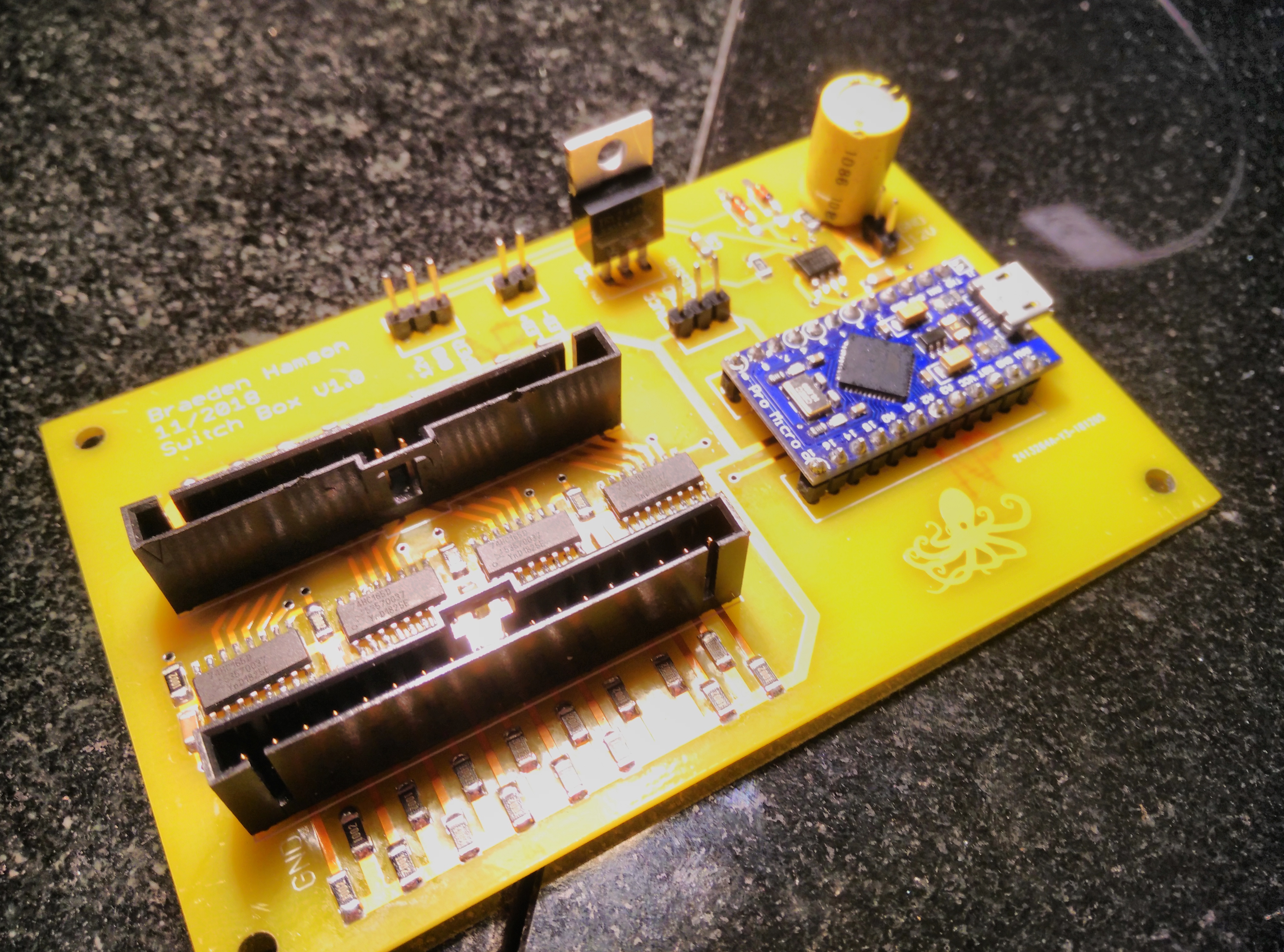
It verks! I was worried while assembling it that I'd missed something in the design. Even though I sat on the design for a month and checked it over periodically. I used solder paste and a hot air soldering system to mount all the components. During assembly I in my infinite wisdom soldered 3 of the shift registers on backwards. To find this out I had to desolder the arduino because I didn't know if it was working. As it wouldn't light up when plugged in. Of course there was a short between VCC and GND which was the reason it didn't light up. The desoldering heat actually warped the board :D but no matter. The pwm circuit works too. Though probing it with my new scope (best xmas ever) showed that the circuit doesn't modulate the duty cycle instead it modulates the frequency. So I don't get a great range of brightness out of my back lighting. But I think I can look at live with that. Though this may have to do with capacitor values within the circuit so, maybe I can fix it. Next up, attaching the switches. Then etching the panel.
-
That's a good explanation of how a shift register works, they were confusing as hell when I first learned about them.
-
Thank you I think your referring to the resistors on the board? I'm the same as Brewnix in this instance I copied a design I saw on SimHQ and then put a 555 pwm circuit for my back lighting dimmer. Anyhow, those resistors are pull up resistors. I'll start with the example of what would happen if it weren't there. Let's say the switch is closed, the shift register will see 0 volts at the switch because it is closed and any voltage that is on the switch will have gone to ground. This is a good thing. Now when the switch is open there's no path to ground but there's also no voltage. So the voltage there could be anything. That's called floating. If we put a resistor on there we can ensure that it has voltage there when the switch is open. And because it uses a relatively high resistance the voltage can still go "0" when the switch is closed because there's a direct path to ground and the current thought the resistor would be small. Like pouring water into a bucket with no bottom.
-
Thanks!
-
This is more of a hypothetical question. I don't have specifics I'm just wondering if there is a limit. Thanks!
-
Thanks, the PCB was made by JLCPCB, and cost $18 shipped for 5 boards. But $8 of that was to have it in yellow. I couldn't say no to that look