Jump to content

Wags

ED Team
  • Posts

    11772
  • Joined

  • Last visited

  • Days Won

    56

About Wags

  • Birthday November 10
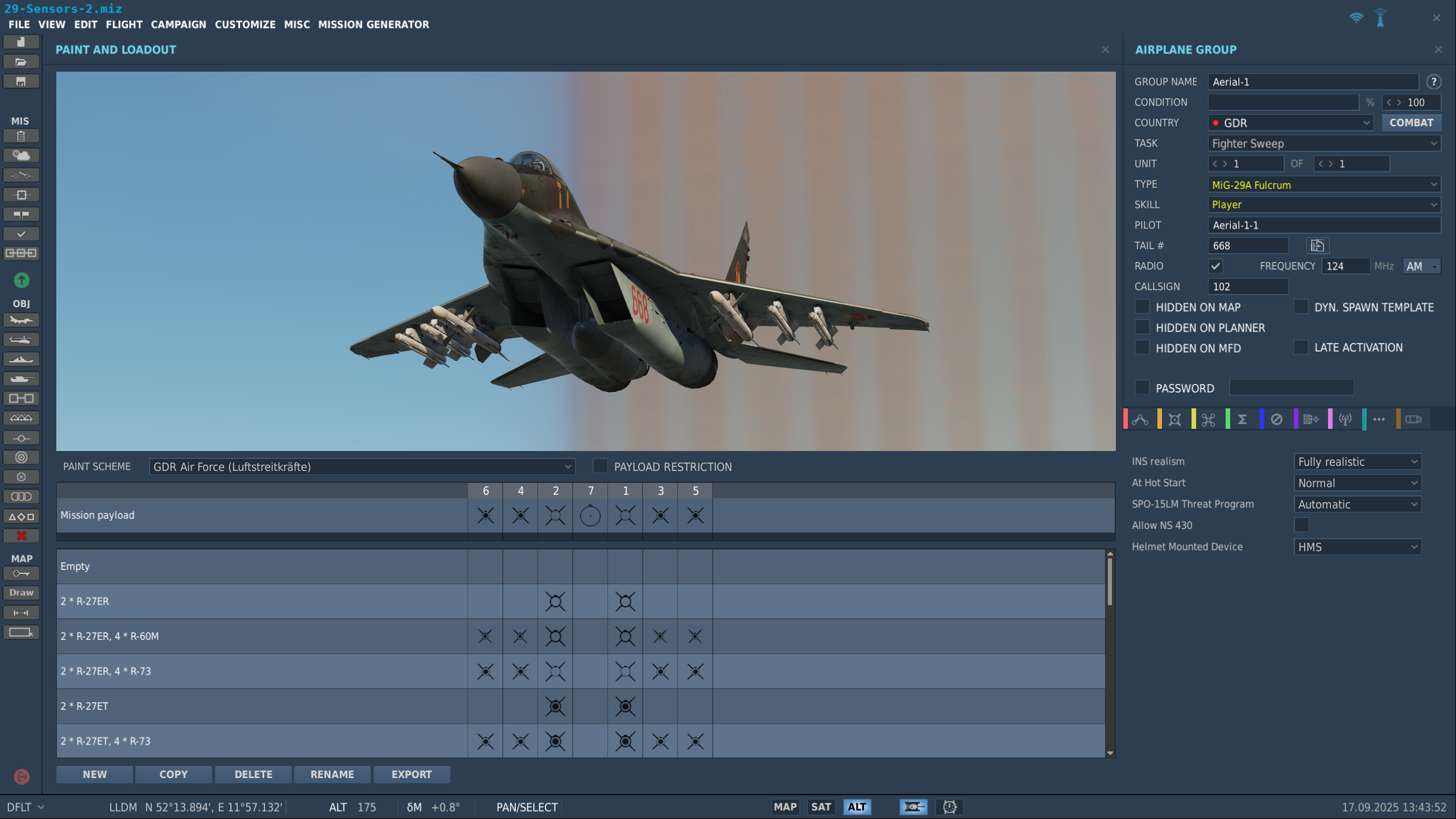
Personal Information

  • Flight Simulators
    DCS World
  • Location
    Phoenix, AZ

Recent Profile Visitors

The recent visitors block is disabled and is not being shown to other users.

  1. DCS: F-16C | Alignment Procedures To further improve the accuracy of the F-16C INS and GPS alignment system, we’ve implemented significant improvements that will later be rolled into other DCS aircraft like the F/A-18C, AH-64D, and A-10C. Proper alignment based on the GPS-era and a normal versus STRD HDG alignment. Proper alignment is critical for accurate navigation, sensor slaving, and weapon accuracy. Known issue: In-Flight Alignment in pre-GPS era requires additional couple of FIXes in addition to the first two OFLY FIX to calculate the velocity properly. These FIXes can be made in any suitable mode: TPOD, FCR, HUD, OFLY, the only requirement is to keep the aircraft at a straight line between the fixes. Of course, the fixes should be done precisely. Once this addressed in a later update, I will create a in-depth instruction video on this topic. GPS-Era / STRD HDG Alignment First, let’s start with the most common form of alignment in DCS, GPS-era using a STRD HDG alignment. This is the simplest, fastest, and most common for single- and multi-player. With power to the avionics systems, set the INS switch to STRD HDG and then set the GPS switch to ON. It’s important that the MIDS switch remains in the OFF position. After about 12 seconds, you’ll see an ALIGN indication on the HUD. You’ll then verify the STRD HDG alignment by going to the DED INS page and check the latitude, longitude, and altitude against your location on the F10 map view. After about 60 seconds, you should be aligned and confirm this by the ADI flags being retracted; HSI showing correct magnetic heading, DME, bearing pointer and CDI deflection; roll and pitch correct on the HUD; and RDY should be flashing on the INS alignment DED page after less than 2 minutes. We can now switch the INS switch from STRD HDG to NAV. On the DED INS alignment page, confirm that GPS TIME is displayed one minute after the GPS switch is set to ON. Note that this may take longer if the aircraft is under cover like a hardened aircraft bunker. As such, it is best to align out of cover. With good GPS TIME, set the MIDS switch from OFF to ON. After alignment with GPS correction, you can expect no more than 40 meters of INS drift. Further, if you zeroize the GPS or are flying a REDFOR Viper, you can expect an INS drift of 100 meters or more. GPS-Era / Normal Alignment A normal alignment is much like the STRD HDG Alignment, but we’ll need to manually enter the aircraft starting location because we’re not using a known, STRD HDG location. To start though, we’ll in the INS switch to NORM and not STRD HDG this time. Then set GPS to ON, verify MIDS to OFF, and wait for ALIGN on the HUD after about 12 seconds. The big difference is now going to the DED INS alignment page and entering the aircraft’s latitude, longitude, and altitude as shown on the F10 map. Once done, we’ll verify ADI, HSI, and HUD as before and wait for the flashing RDY indication on the DED INS alignment page after about 8 minutes. Once flashing, set the INS switch from NORM to NAV and verify GPS TIME indication. With that, set the MIDS switch from OFF to ON. These will be the most common alignment scenarios when performing a cold start. However, you may come across a mission or campaign with a date prior to the GPS era. In that case, we’ll only align based on INS with no GPS correction. Non-GPS Era / STRD HDG Alignment Like the GPS-era, set the INS switch from OFF to STRD HDG and wait for the ALIGN indication on the HUD. Then, verify the DED INS alignment page latitude, longitude, and altitude to the F10 map data and verify ADI, HSI HUD, and wait for the flashing RDY indication. We can now move the INS switch to NAV. Once airborne, you’ll then want to conduct alignment FIX procedures using Overfly, targeting pod, HUD, or FCR to remove accumulated INS drift. Please see the earlier videos on fix taking. Non-GPS Era / Normal HDG Alignment The last weight-on-wheels we’ll look at is doing a normal alignment at a mission date prior to GPS. Set the INS switch from OFF to NORM and wait for the ALIGN indication on the HUD. From the DED INS alignment page, enter the aircraft’s latitude, longitude, and elevation using the F-10 map. Next, verify the DED INS alignment page latitude, longitude, and altitude to the F10 map data and verify ADI, HSI HUD, and wait for the flashing RDY indication after about eight minutes. We can now set the INS switch to NAV. Once airborne, you’ll then want to conduct alignment FIX procedures using Overfly, targeting pod, HUD, or FCR to remove accumulated INS drift. Please see the earlier videos on fix taking. So far, we’ve only been talking about weight-on-wheels alignment procedures. We’ll now shift gears and discuss in-flight alignment. We’ll start with the more common GPS-era procedure. GPS-Era / In-Flight Alignment First, set the INS switch to FLT ALIGN and flight straight and level until the ADI flag is retracted. You’ll see INS FLT ALIGN on the DED and STBY on the HUD. Maintain straight and level flight and enter your compass magnetic heading within 20 seconds on the DED and verify that the pitch ladder is displayed on the HUD. Continue to fly straight and level until the ALIGN is replaced with the maximum G value on the HUD and then return the INS switch to the NAV position. Non-GPS-Era / In-Flight Alignment Last, for an in-flight alignment with no GPS, set the INS switch to FLT ALIGN and fly straight and level until the ADI OFF flag is removed. INS FLT ALIGN should appear on the DED and STBY on the HUD. Fly straight and level and enter your magnetic heading on the DED within 20 seconds while ALIGN appears on the HUD, replacing the maximum G indication. We’ll now perform an OFLY FIX within the next 30 seconds. It is required we perform a second OFLY FIX within two minutes to correctly perform velocity calculations. Keep flying straight and level, and once the maximum G field replaces the ALIGN indication, you are done. For best INS alignment, you may wish to perform an OFLY, HUD, FCR, or TGP alignment every 15 minutes for best possible navigation and acceptable weapon accuracy. Manual Alignment as Backup The manual alignment is a backup alignment designed to provide get-home capability only.
  2. You are very welcome. I look forward to more such videos every couple of weeks, or so. Kind regards, Wags
  3. Dear all, After talking with lee1hy, we've decided that he'll be providing the requested skins, and quite a few more. He does fantastic work that I believe players will enjoy. In the end, we want to provide the best possible F-16C liveries to our customers. After a careful review of the F-16C user file skins, we believe that lee1hy provides outstanding F-16C skins that meet our needs. Further, by using a single source, it greatly streamlines the process. It was my mistake creating this topic prior to carefully reviewing the F-16C user files skins before making this decision. Kind regards, Matt
  4. Dear all, I'd like to add default F-16C skins to several more countries: 1- Norway 2- Egypt 3- Denmark 4- Belgium 5- The Netherlands 6- HAVE GLASS skins for OH, SP, SP, and WW. All submission should be standard gray birds, not "peacock" and fantasy paint schemes. Please feel free to list your skins here if you'd like to be considered. I can offer ED Miles and credit in the newsletter as thanks. Kind regards, Matt
  5. OP updated, C scope also now in work.
  6. Dear all, If I might interject. After not having flown a Case 3 in forever, I tested it in the current, public Open Beta today, and it worked as it should (I was more than a bit sloppy though). I suspect where some folks may be running into problems could be: 1- The mission does not have a Link 4 assignment to the carrier. Press and hold the K key to check. 2- You did not first establish yourself in ATC. 3- You tried to Couple outside of line up and glideslope Tilt limits. I've attached a track to illustrate that it works as designed when performed correctly. Wags ACLS-Test.trk
  7. Left on the sight select switch on the collective. Same for pilot and CPG
  8. Without a track or video it’s impossible to know where you are going wrong. But this video should get you started.
  9. Trying to designate an individual contact on the FCR page with the HOCAS cursor while flying at the same time is not recommended and why I did not mention it in my most recent video.
  10. You could slew the HOCAS cursor over the desired target and depress to designate as the NTS. What was the NTS becomes the ANTS.
  11. Changes Coming to Sighting Point/Cursor Slews, Snowplow, and VIP/VRP Logics COMING SOON Dear all, In the next update to Open Beta, you can expect a large number of fixes for the DCS: F-16 Viper. Over the past six months, the F-16 team has been revamping the aircraft's air-to-ground sighting and weapon delivery sub-modes to be more authentic and to address many reported bugs in how the F-16 integrates it's sensors, HOTAS, and targeting logic. Along with the upcoming changes to the datalink within the F-16, this has been a very large task that required our dev team to address many aspects of the F-16 all at once, due to the level of integration such changes would require within the aircraft systems. Understandably, this may seem like a lot of changes, but for the most part very little will actually change within the DCS F-16. These changes are mainly focused on ensuring all the minute details that are required for the F-16 avionics to function are properly implemented to prevent any sort of logic conflicts when using the air-to-ground targeting systems. While the Early Access Guide is still receiving revisions to sufficiently explain how all of these weapon delivery sub-modes are intended to work within DCS F-16, we are including a brief conceptual overview for our Viper players to frame the underlying logic in hopes that it will enhance everyone's understanding of why these updates were necessary; until the Early Access Guide can be updated to reflect these concepts. F-16 Conceptual Overview The F-16 sensors (FCR, TGP, and HTS) drive a singular System-Point-of-Interest (SPI). As such, only one sensor can be in a track mode at any given time. When any sensor enters a track mode, it will cause the other sensors to exit their track mode. For example, if the FCR is in Fixed Target Track (FTT) against a surface target location and the TGP enters POINT track, the FCR will exit FTT. This is because the non-tracking sensors must remain aligned to the tracking sensor to maintain the singular SPI location. If two sensors were in track mode simultaneously, the single SPI logic of the F-16 would be violated. When a sensor enters a track mode (FCR FTT/MTT, TGP AREA/POINT, or HAD designation), this automatically puts DTOS, VIS, or EO-VIS into a post-designate state at the corresponding location. The F-16 A-G master mode includes many weapon delivery sub-modes that may be used, depending on the weapon selected on the SMS page. These sub-modes are categorized as either "Pre-planned" or "Visual" weapon delivery sub-modes. "Pre-planned" sub-modes revolve around the use of steerpoints that have been programmed at pre-planned target locations. These sub-modes include CCRP, LADD, PRE, EO-PRE, and EO-BORE. (PRE is used with AGM-154A, GBU-31/38, CBU-103/105, or GBU-24; EO-PRE and EO-BORE are only used with AGM-65) These sub-modes permit direct sighting options (STP/TGT) or offset aimpoint sighting options (OA1/OA2), as well as the Snowplow sighting method. Sighting points are used to ensure the accuracy of the targeting solution to the target steerpoint prior to weapon release. Offset aimpoints are not targets themselves, but are used to ensure the target location (TGT) is accurately placed for weapon delivery (i.e., due to INU drift in a pre-GPS scenario) The selected sighting point determines where the System-Point-of-Interest (SPI) is placed relative to the steerpoint, which directs all sensors to a singular location. Snowplow permits employing a "Pre-planned" weapon delivery mode when existing steerpoints are not practical, and provides a means to rapidly direct the SPI in front of the aircraft at the Snowplow cursor. If a designation is performed while in Snowplow, the main Navigation cursor is slewed to that location and Snowplow is exited. "Visual" sub-modes are geared toward visually acquiring a target location independently of a pre-planned steerpoint. These sub-modes include CCIP, STRF, DTOS, VIS, and EO-VIS. (VIS is used with AGM-154A, GBU-31/38, CBU-103/105, or GBU-24; EO-VIS is only used with AGM-65) Sighting options are not available in these sub-modes, nor is the Snowplow sighting method. The sighting option rotary and the Snowplow OSB options are removed when these sub-modes are entered. These modes will automatically place the FCR in AGR (Air-to-Ground Ranging) and the mode cannot be changed except for placing it in OVRD/STBY. The TGP (if installed) is automatically slaved to the weapon solution in CCIP or STRF sub-modes. The TGP (if installed) is slaved to the TD Box in DTOS, VIS, or EO-VIS sub-modes, even when these modes are in a pre-designate state. This augments the visual identification of targets and assists in optically locating targets at extended ranges. When a target location is designated in DTOS, VIS, or EO-VIS sub-modes, this also updates the current steerpoint location by moving the Navigation cursor to the same location. This ensures a seamless transition between sub-modes (Example DTOS->CCIP->CCRP) against the same target location in which the SPI is maintained on the target. Visual Initial Point (VIP) and Visual Reference Point (VRP) sub-modes are a means of conducting strikes against pre-planned target locations in CCRP sub-mode while using visual landmarks for final alignment of the targeting solution. These are especially useful when conducting low-level strikes in which the target may not be visible until just prior to weapons release. These sub-modes permit cursor slews to be performed to align the targeting symbology with visual landmarks without affecting the cursor deltas of the main Navigation cursor. VIP adds "IP" as an additional sighting point option that may be selected using TMS Right-Short while the HUD or FCR is SOI, or by pressing the corresponding sighting point rotary at OSB 10 on the FCR or TGP MFD formats. When VIP mode is entered, the sighting point is automatically set to "IP", after which the sighting points may be advanced in a sequence of IP->TGT->OA1->OA2->IP. VRP adds "RP" as an additional sighting point option that may be selected using TMS Right-Short while the HUD or FCR is SOI, or by pressing the corresponding sighting point rotary at OSB 10 on the FCR or TGP MFD formats. When VRP mode is entered, the sighting point is automatically set to "TGT", after which the sighting points may be advanced in a sequence of TGT->OA1->OA2->RP->TGT. These modes allow a single overfly designation of the IP or RP in which the SOI is automatically set to the FCR and the sighting point is set to the TGT. This allows a seamless transition with one button press from the ingress phase into the final attack phase, without the requirement to manually slew the cursor to align the diamond symbol in the HUD with the physical landmark that represents the IP or RP. Changelog: Sighting Points & Cursor Slews Cursor slews are now possible in several different modes that are independently accumulated. As an example, the VIP cursor may be slewed and zeroed independently of the Navigation cursor. If Cursor Zero is pressed and "CZ" remains displayed on the MFD, it is because another cursor still has cursor slews applied. This may be seen when the DTOS/VIS cursor is zeroed back to the FPM, but the main Navigation cursor may still be slewed away from the original steerpoint location. To zero the Navigation cursor, CCRP or CCIP should be entered and then CZ pressed. When cursor slews are applied, Cursor Zero is needed to remove them. For a time, changing the selected steerpoint was erroneously zeroizing the cursor when it should not have been. This has been rectified so that cursor deltas are maintained during steerpoint switching (ie, if the TGP was looking 500 meters west of steerpoint 1, it will be looking 500 meters west of steerpoint 2 if the STPT is advanced from 1 to 2). The TD Box occludes the steerpoint diamond. If they are co-located, which is the case in "Pre-planned" A-G sub-modes like CCRP or LADD, the steerpoint diamond will be hidden by the TD Box. When the steerpoint is slewed using the cursor, the OA1 and OA2 offset aimpoints will always slew with it to maintain their programmed offset distance/direction as entered on the DED DEST page. Pressing Cursor Zero no longer zeros the OA1/OA2 settings. These can only be zeroed by manually editing the RNG value to 0 on the DED DEST page. If the RNG value of OA1 or OA2 is set to 0, the OA triangle symbols will be removed from the HUD/HMCS and will not be available in the sighting point rotary options. OA1 and OA2 will not be available in the sighting point rotary options if FIX or A-CAL are displayed on the DED. When not in VIP or VRP modes, the OA1 or OA2 triangle symbols will not be displayed in the HUD/HMCS if not selected using the sighting point rotary option. When in VIP or VRP modes, both OA triangle symbols (if RNG is not 0) are always displayed along with the IP/RP diamond, TGT TD Box, and PUP circle symbols. Sighting point options are not available if in any "Visual" weapon delivery sub-mode: CCIP, STRF, DTOS, or VIS; or if MARK is displayed on the DED with "HUD" as the marking method. Sighting points may be cycled using TMS Right-Short while the HUD or FCR is SOI (prior to this it was only possible with FCR as SOI). The "Ghost A-G Cursor" (white crosshairs) is now displayed on the HSD at the current sighting point location for all sighting points (including OA1, OA2, IP, and RP). Prior to this it was only displayed when TGT was the selected sighting point. The Azimuth Steering Line will only be referenced to the TGT sighting point location, even if the sighting point is changed to OA1, OA2, IP, or RP. Only the direct sighting point (TGT) can represent the target solution for weapon delivery; offset aimpoints only assist in alignment of the targeting solution. Only one sensor can be in a "track" mode at any given time, since the SPI represents the location to which all aircraft sensors are directed. Entering a track mode in one sensor will cause other sensors to break lock. If FCR enters FTT or MTT, the TGP will exit POINT/AREA track and any HAD designation will be dropped. If the TGP enters POINT or AREA track, the FCR will break FTT/MTT lock and any HAD designation will be dropped. If a threat radar symbol is designated on the HAD, the FCR will break FTT/MTT lock and the TGP will exit POINT/AREA track. If the sighting point is changed, the aircraft sensors will exit their respective tracking modes to prevent cursor slews from being erroneously input into the system. The TGP is automatically slaved to the DTOS/VIS TD box while in pre-designate state. If in DTOS/VIS sub-mode and a sensor is commanded into a track mode, the sub-mode will automatically enter post-designate state at the corresponding sensor track location. (ie, if the TGP is SOI and being slewed in DTOS mode and commanded to POINT track, DTOS will enter post-designate at that location) If in any "Visual" weapon delivery sub-mode (CCIP, STRF, DTOS, or VIS; or if MARK is displayed on the DED with "HUD" as the marking method), the FCR will enter AGR mode and cannot be changed. FCR mode selection page is corrected to prevent manually changing the FCR out of AGR mode without changing the weapon delivery sub-mode. When a laser-guided bomb is selected in SMS, the TGP laser will be inhibited from firing if the sighting point is set to OA1, OA2, IP, or RP. This prevents an LGB from being diverted from the intended target location, which is represented by the direct sighting points of TGT or STP. Snowplow Snowplow is only available while in a "Pre-planned" weapon delivery sub-mode: CCRP, LADD, PRE, EO-PRE, EO-BORE; or if in NAV mode if the FCR is not in an A-A mode. When Snowplow is entered (via OSB 8 on the FCR or TGP MFD formats), the SPI is placed at the location of the Snowplow cursor in a pre-designate state (represented by the TD Box in the HUD). In NAV mode when there is no TD Box and the steerpoint diamond represents the steerpoint location, there will be no HUD symbology corresponding with Snowplow cursor while in a pre-designate state. If TMS Up-Short is pressed while the HUD, FCR, or TGP are SOI, Snowplow is exited via post-designate and the main Navigation cursor is moved to the location of the SPI (represented by the TD Box in A-G master mode or the steerpoint diamond in NAV master mode). If Snowplow is exited from pre-designate by pressing "SP" at OSB 8 on the FCR or TGP MFD formats, the SPI simply returns to the existing location of the main Navigation cursor since a designation was not performed. The Snowplow cursor location is placed in three dimensions by the following. Aircraft Heading: The cursor will remain along the aircraft longitudinal axis and cannot be changed. Range: The cursor will be placed in front of the aircraft at 50% the A-G FCR range. Adjusting the FCR range (even if the FCR is in OVRD or STBY modes, or if the RF switch is in QUIET or SILENT) will move the Snowplow cursor in range. If the FCR is powered OFF on the SNSR PWR panel, the Snowplow cursor is fixed 5 NM in front of the aircraft and cannot be changed. Elevation: The cursor is set to the same elevation as the current steerpoint while in pre-designate. When Snowplow is exited via post-designate, the elevation of the SPI is re-calculated to the terrain elevation. When weight-on-wheels, the cursor is set at the same altitude as the aircraft. VIP/VRP It is no longer possible to enable VIP and VRP for the same steerpoint. Enabling one mode will disable the other if set to the same steerpoint. When VIP or VRP mode is entered, a Cursor Zero is no longer performed to the main Navigation cursor. When an overfly designation is performed in VRP mode, the designation will now designate the location of the RP, not the TGT. Only one overfly designation may be performed of the IP in VIP mode or the RP in VRP mode, using TMS Forward-Short while the HUD is SOI. Cursor slews may still be performed before or after the designation, but VIP and VRP modes must be exited and then re-entered to perform subsequent overfly designations. When entering VIP mode, the EHSI will be directed toward the IP and the Azimuth Steering Line will be to the TGT. When an overfly designation of the IP is performed, the EHSI will switch to the TGT. When entering VRP mode, the EHSI and the Azimuth Steering Line will be to the TGT, even after an overfly designation of the RP is performed.
×
×
  • Create New...