Yo-Yo
-
Posts
17758 -
Joined
-
Last visited
-
Days Won
8
Content Type
Profiles
Forums
Events
Everything posted by Yo-Yo
-

Discrepancies in the Su-27 longitudinal fly-by-wire system (SDU-10)
Yo-Yo replied to DummyCatz's topic in Su-27 for DCS World
Yes, and it was done intentionally. We still have no confirmed data on whether trim schedule block is operative during DIRECT MODE, but we can make an educated guess, that it zeroed, using several facts: DIRECT is an emergency mode for catastrophic SDU failure while scheduler signal can be false too. Using this signal deadly connected to the system seems to be very optimistic.; the scheduler can be switched off or zeroed by means, for example, of switching of its supply. this scheduler is a mean to mimic natural positive velocity-stable trim characteristics when SDU is operative and maintain neutral velocity stability within the whole range of Mach number. all sources mention "direct link using separate electric supply" but no source mentions this scheduler active. But if some different and confirmed information is available - things can be changed. -
Discrepancies in the Su-27 longitudinal fly-by-wire system (SDU-10)
Yo-Yo replied to DummyCatz's topic in Su-27 for DCS World
As far as I can see in DCS, OPR works exactly as it should and according your expectations. 1 - Limiter rod is in its forward limit 2 - The stick goes aft quite slowly, watch the gap. 3 - One or two parameters are out of their limits, shaker on, watch the gap (no gap), pilot overrides the OPR 4 - Stick moves too fast, and pilot overrides it. "The gap", if you mean the control window, is a distance between the center of the stick circle and the pushrod symbol.
-
I agree that almost constant C coeff up to 90-90 degree of AoA is a clear sign of body-fixed system, so your calculations were correct. I have no access to the article you refer to, and I would like to have a look at the whole article, because discussing the thing using only excerpts can not be very fruitful. For example, CoG position of the plane that was tested for this article (earlier model) can be different (more aft) from the plane that was modelled in DCS (later variants). So, any discussion of issue related to trim are useless without knowing the exact CoG position. And, by the way, I can not admit ~70 of steady trim angle shown in the article because of trim data I have. Referring to quite different F-16 aerodynamics is not very useful in this case. So, 40-50 degrees regarding CoG is correct value. When developing the model, the primary objective was to achieve the most accurate representation of steady-state flight regimes, as these regimes, being the most prolonged in duration, have the greatest impact on the flight trajectory and the maneuvering characteristics of the aircraft. Dynamic changes in lift coefficient during rapid changes in angle of attack are a phenomenon well-known at least since the 1940s. This behavior occurs universally and is not limited to aircraft such as the Su-27 or MiG-29, as might be inferred from the article by G.I. Zagaynov. We could theoretically use this effect in flight modeling (FM), the mechanism is no mystery to us. However, before demanding this from developers, consider the following questions: To what extent would a trajectory or a trajectory parameters differ from calculations using a static lift coefficient if a very brief 30% increase in load factor occurs during an increase in angle of attack, followed by a subsequent decrease when the angle reduces, given that velocity is an integral and displacement is the double integral of acceleration? Given that reliable data on the hysteresis loop shape for the lift coefficient (Cy) is available for only a handful of aircraft, do you believe applying unsteady aerodynamics exclusively to these aircraft is fair to others? Alternatively, would it be valid to use data obtained, for example, for the Su-27 to model the F-18?
-
I think, I answered the question in the previous post.
-
Status bar shows acceleration in local body-fixed coordinate system. Cy in all articles and documents is given for velocity coordinate system. It is almost correct to neglect this difference for low AoA, but it is not correct to mix them in the common formula in the case of high AoA. Thus, this calculations operating with only Cy value has no sense in this case.
-
Все, что касается связи ручки и стаба полностью реализовано. Это легко можно увидеть. В общем ответ правильный, поскольку основан на такой же полной реализации ГС в других модулях. Кроме этого, при повреждениях могут реализовываться особенности аварийного функционирования ГС.
-
Вопрос все же был в итоге сформулирован как утверждение. Если подразумевалось, что ни один в ДКС, это несколько меняет смысл предложения. Однако хочу напомнить одну из многочисленных историй от Швейка, когда некорректно сформулированная фраза приводила к неожиданной реакции окружающих ("Нужно говорить всегда ясно и вразумительно, а не обиняками. "У Брейшков" много лет тому назад работал один управляющий..." )
-
Это особенности самолета. Если посмотреть на балансировочные кривые самолета в ГП, то хорошо видно, что для того, чтобы просто удержать самолет в ГП на сверхзвуке, особенно на малых высотах, требуется отклонение ручки 70-90 мм от себя, что уже практически полностью исчерпывает запас хода вперед. Кроме этого на сверхзвуке сильно увеличивается запас продольной устойчивости, из-за смещения фокуса самолета назад. О какой серьезной перебалансировке в сторону отрицательных перегрузок там вообще можно говорить?
-
Negative sir, YOU HAVE to trim it at every power change. And, finally, you have to prove that DCS P-51 or any other prop plane have very different trim curves from the curves that were recorded for the real plane. And only these graphs give adequate information, how it should be.
- 38 replies
-
- 12
-

-
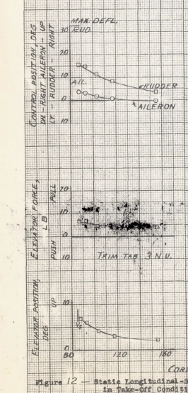
You’re mixing up torque with P-factor and downwash effects. Torque is a rotational moment generated as a reaction to the propeller’s swirling air mass (according to the conservation of angular momentum), which creates a leftward rolling moment on the aircraft. Right rudder is primarily applied to counteract yaw caused by P-factor and downwash effects, not torque itself. At positive angles of attack (AoA), the P-factor creates a leftward yaw and positive pitch moment by increasing AoA on the descending blade, becoming more pronounced with increased speed due to differential airflow over the propeller blades. Downwash is more influential at low speeds , decreasing as speed increases. Meanwhile, P-factor takes effect once there is sufficient speed and high AoA to cause noticeable local AoA changes on the propeller blades. Overall, the interaction of these forces and their impact on rudder trim requirements are clearly visible in trim diagrams. Torque itself requires very slight ailerons input.
- 38 replies
-
- 10
-
-
Returning to the Corsair video... It is obvious, that the initial movement was AOA increasing (wrong trimmer, uncontrolled stick movement, wind gust - I can not say), then left yaw that was a result of increased P-factor due to high AoA, and only after that roll started as a result of sideslip. The well known P-51 accident, when the plane flips over, was started just at the moment when the pilot decided to wave-off just before the touchdown and applied full power. Try this with DCS P-51, and the result will be the same.
-
Torque in this kind of aircraft is mostly yaw effect than roll. This is trim curves for take-off power for P-51 that show very low aileron deflection to trim the plane even near stall. In DCS we can see exactly the same.
-
No, we can not. DASH is a functional analog of natural stable airplane where the trim speed is a function of the stick position. Without DASH it resembles a plane with neutral stability, where any speed requires almost the same stick position. The way you described control algorithm is the second case.
-
To be accurate, it's better to say that they use different FM but both FM have the same trajectory and energy parameters (engine power at altitude, lift capabilities, L/D polars, etc). It means that AI will have all trajectory capabilities as human. As far as I can see, the history of LockOn/DCS is not known nowadays... so, I have to remind a little: LockOn used SFM for flyable aircraft and very basic AI FM for airplanes and helicopters that was far from physics. SFM is a classic trajectory model based on lift/drag and power/thrust and can be tuned very well for a certain aircraft to have exact performance figures. As the human FM was migrating to AFM/PFM, two movements began: for Ka-50 project all AI helicopters were upgraded for helo-GFM, based on the same solid body physics (contact physics, MOI, forces and moments), and simplified rotor and engine physics (I say PHYSICS! ); for AI planes SFM physics was implemented, that gives them true performance.
-
-
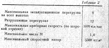
Да, потому что 8 - это та перегрузка, которую летчик не должен превышать по условиям прочности и ДОЛГОВЕЧНОСТИ планера. Это никак не относится к его физиологии. Т.е. оторвет при мгновенном превышении разрушающей перегрузки (12 в данном случае), но увидит это интересное событие в полном сознании и совершенно незамутненным взором. В экстремальных условиях боя, боту при необходимолсти разрешен выход до 10 (чем, в общем, грешат и живые люди). Система же ограничения по физиологии работает уже совсем иным образом с учетом предыстории создания и удержания перегрузок, включая разогрев и усталость. Поэтому бот на достаточно длительных перегрузках без ППК будет придерживаться 5-5.5g, тем более, что у него перегрузки ограничиваются еще и логикой сохранения и набора энергии.
-
Я все же настоятельно рекомендую прочитать текст более внимательно: БОТ ИСПОЛЬЗУЕТ ТУ ЖЕ СИСТЕМУ, что и хуман. Поэтому и его усталость и те перегрузки, что он в состоянии выдержать так же зависят от того, какие ППК прописаны для данного типа самолета. Т.е., если в МиГ-15 ППК не выдают, а в F-86 есть, допустим, первого поколения, то и ограничения будут отличаться, причем одинаково, как для человека, так и для бота. Чудотворное значение ППК отосительно кратковременных перегрузок не стоит преувеличивать. Он не снижает усталость, он просто препятствует оттоку крови в нижние части тела, иными словами, делая физически возможным кровоснабжение мозга и глаз при действии достаточно длительных перегрузок. Переносимость кратковременных больших перегрузок он практически не улучшит. В общем-то, на соревнованиях на спортивных самолетах никто ППК не использует именно потому, что хоть там и экстремальные перегузки, но они кратковременны.
-
Nothing was changed except the landing gear.
-
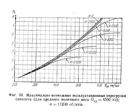
По порядку: боты тянут до 10, если позволяет динамика самолета, в течение очень короткого времени ( менее 3-4 с), которое определяется временем блекаута по той же системе, что и для человека. Разница только в том, что человек при наступлении блекаута может под свою ответсвенность еще немного потянуть (и достичь полной нирваны с отключением, если переберет), а у бота приближение полного блекаута - это категорический императив, и он отпускает ручку. ППК не играет никакой роли при кратковременных перегрузках, т.к. человек переносит кратковременные перегрузки до 3-4 секунд просто за счет запасов О2 в клетках глаза и мозга даже без заметных нарушений зрения. Поэтому все рассказы о том, что "у МИГов перегрузки не превышали 6" относятся к достаточно продолжительным перегрузкам, возникающим на стандартных фигурах пилотажа. именно потому, что 5.5-6 - это как раз физиологический предел переносимости без ППК. О том, какие перегрузки считались допустимыми для советских самолетов еще в начале 40-х, говорят и нормы прочности для истребителей. Норма прочности 1947 года для МиГ-15 - 8 эксплуатационная, 12 разрушающая для расчетной массы. Может ли он физически развить перегрузку выше 8? Запросто, смотрим график - 8 на 600 км/ч на малых высотах (сравнительно небольшое число М) и, соответственно, 10 будет уже где-то около 700. Хватит ли там коэффициента подъемной силы? Более подробный расчет с учетом числа М и использованием кривых максимального Су для различных чисел Маха тоже дает положительный ответ. Последнее - а хватит ли сил вытянуть ручку? ТО самолета дает ответ и на этот вопрос: вполне, особенно если в критической ситуации и двумя руками. Для самолета приводятся как углы отклонения РВ так и усилия на единичный прирост перегрузки: примерно 3-3.5 кГ в интересующем нас диапазоне скоростей, т.е усилие на 10g не будет превышать 40 кГ, отклонение РВ - 20-22 градусов. Примерно к таким же выводам приходили и разработчики самолета (см графики). Так что можно, конечно, и самому урезать бота и с радостной улыбкой наблюдать соответствие его поведения собственным представлениям о реальном мире, при этом не обращая никакого внимания на то, что бот Сейбр при необходимости тоже может и 10 выжать.null null
-
Mosquito wing comes off at as low as 4.9G
Yo-Yo replied to J13 Serenity's topic in Bugs and Problems
By the way, looking at the bending wings of the Mosquito and looking at the ripped off wing you can be sure that it is bending amount and ultimate load that were documented in the wing strength report. -
Yes, they have a copy of cooling system human plane has.
-
They use the same trajectory physics and the same energy possibilities (drag, induced drag and propeller effective power) as human. The only difference is that AI carefully manage energy never pulling excessive g.
-
DCS МИГ-29 ФМ и всё что связано с аэродинамикой 29го
Yo-Yo replied to Leva's topic in DCS: Горячие Скалы
Спасибо! Десяток-другой килограмм на домашнем джойстике?? Или что?