Jself
-
Posts
119 -
Joined
-
Last visited
Content Type
Profiles
Forums
Events
Everything posted by Jself
-
 I will post them once I finish the build, it is very much a WIP right now. I didn't document my Hornet build very well, so I'm trying to do a better job this time around.
 -
I found your files and am working on a build. I redesigned it slightly to use a min stick and 4 way+push hats for the grips. I mirrored the parts in tinkercad for the left grip and adjusted the controls to match the real one. I have a 2 stage trigger designed. I'm currently working on sanding and filling the right grip while the center parts are printing. I plan to use 3 Arudino micros with a 6x6 button matrix and 2 axis (3 for the center section). Thanks for sharing the files!!! Part 1 of my build https://youtu.be/dxNo1tBHWPc
-
no.. I just used screen shots form the game and some stuff I found searching google and used MS publisher to size them correctly. The clear is just some clear plastic sheeting I got at Hobby Lobby and cut with scissors
-
The Diodes are required if you ever think you will have 2 (or more) buttons pressed at the same time. Without the diodes it will cause ghosting and you will not gettthe output you're expecting. I used momentary toggle switches but still did the diodes just incase. You basically wire them inline on either the rows or the columns of the matrix but not both. As far as making multiple UFCs..It would require each to have their own arduino, and you would have to come up with some kind of a swappable mount I never got around to making a wiring diagram. The Arduino sketches I provided both use a 5x5 matrix. here is a good video on how to wire that up -
-
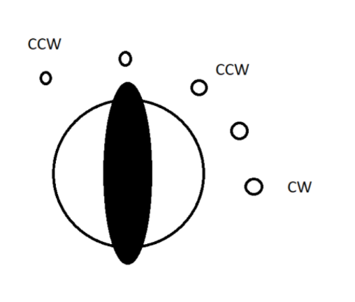
no modifications.. not sure why it works but it does. I use a 5 position rotary switch but only 3 of the positions are wired in and the bindings are as follows

-
very nice - the side consoles stl files are no in the google drive with the front panel files
-
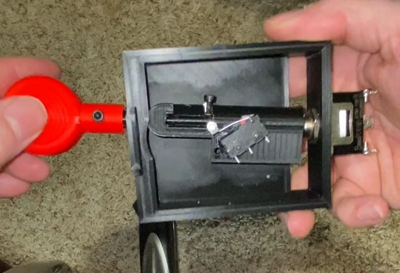
Its a Squard D brand switch. The model is in the readme sweet!!! - If you look at the pic of mine I posted earlier.. the microswitch didn't work too well in the holes in the body.. I had to off set it a bit and bend the arm to get it to work consistently
-
Its a flat aluminum bar that runs the length of the winwing (inside) and bolts to the mounts on the front too. If you have trouble, I can make the STLs for an adaptor pretty easily , just let me know
-
I appreciate it man.. Hope you enjoy your pit as much as I do!!
-
STL files have been added to my shared google drive. Info in the Read Me pdf. Donations appreciated but not mandatory - paypal - jself1@gmail.com https://drive.google.com/drive/folders/1CxYMFzfWFkWKXHwS2IiQCrdIfeTMGgU4?usp=sharing
-
not yet.. working on getting them uploaded..check back in a few days. That switch will work fine...
-
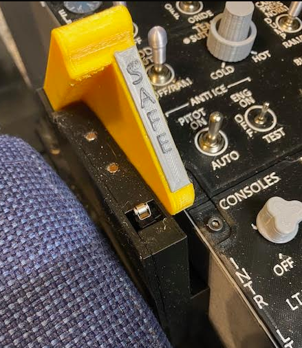
you nailed it. I raised the text 0.6mm (3 layers) then printed the last 2 layers in white
-
I wasn't referring to you specifically. I did basically the exact same thing for an F-18 pit and you can go back through the forum posts and my youtube videos and there are quite a few comments along the lines of "why go to so much trouble for a VR pit...you can't see it" Also quite interesting that you're calling me out for being negative when your comment was " I really doubt that it'll get you the result that you're hoping for"
-
Great work.. Looking forward to seeing the final result. Don't get too discouraged with all the "why do all this for VR" crowd. I did something very similar for the hornet (a couple of threads in this forum) and its doesn't take long for your brain to develop the muscle memory to be able to reach out and find the controls even if they aren't exactly in the right spot. I'd recommend using the fuzzy side of velcro or cabinet door bumper pads on certain buttons so you know where you are at. I use them on the middle OSB on the Hornet MFDs and it makes it really easy to quickly feel for the one you need - https://www.amazon.com/Cabinet-Bumpers-Dampening-Drawers-Picture/dp/B0826JPLPP/ref=sr_1_6?dchild=1&keywords=bumper+pads+small&qid=1632540378&sr=8-6. I bet you could do something similar with the keypad and it won't take you long to be pretty quick with it
-
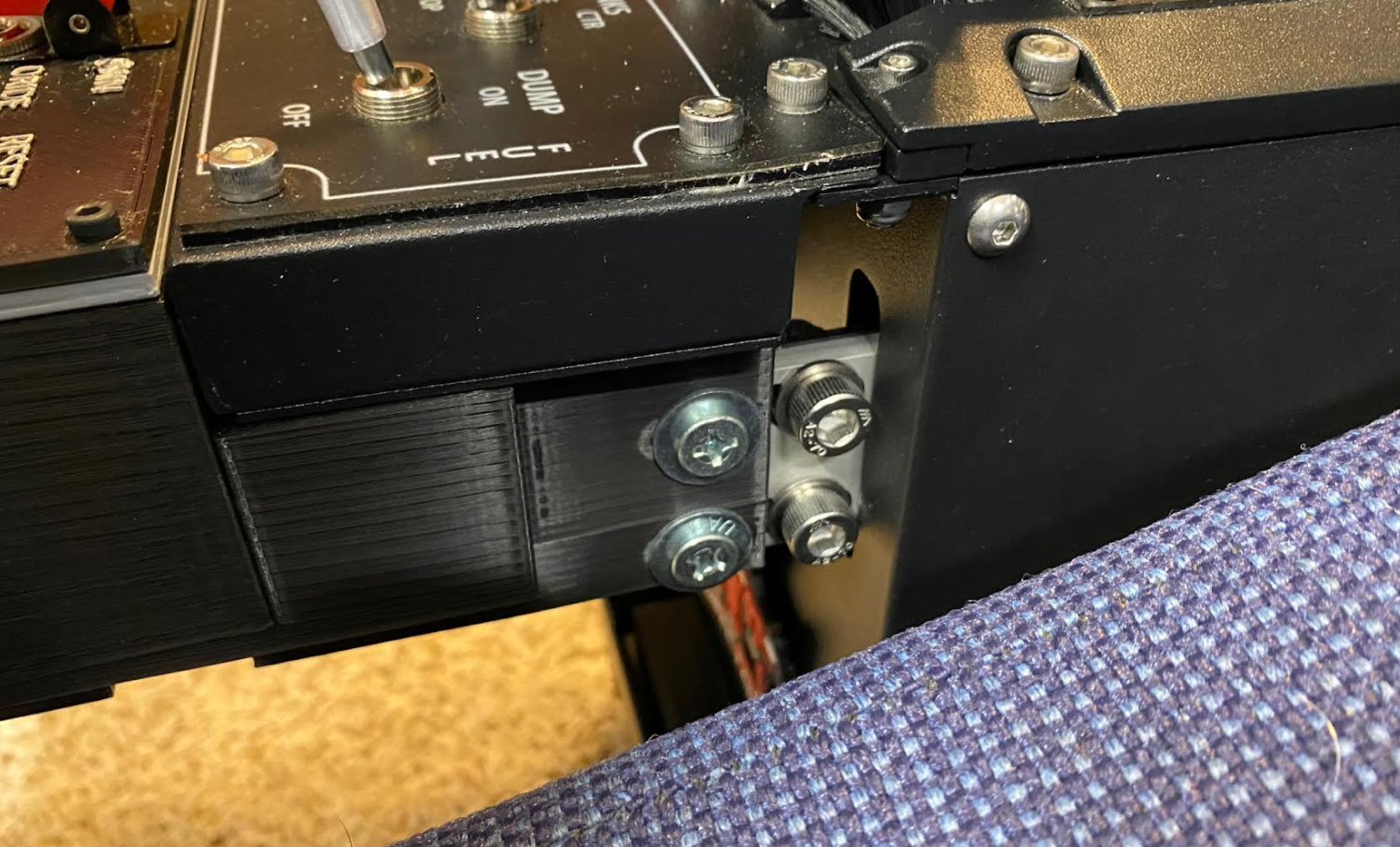
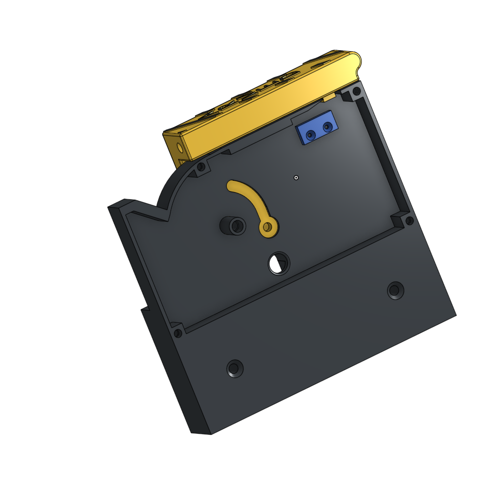
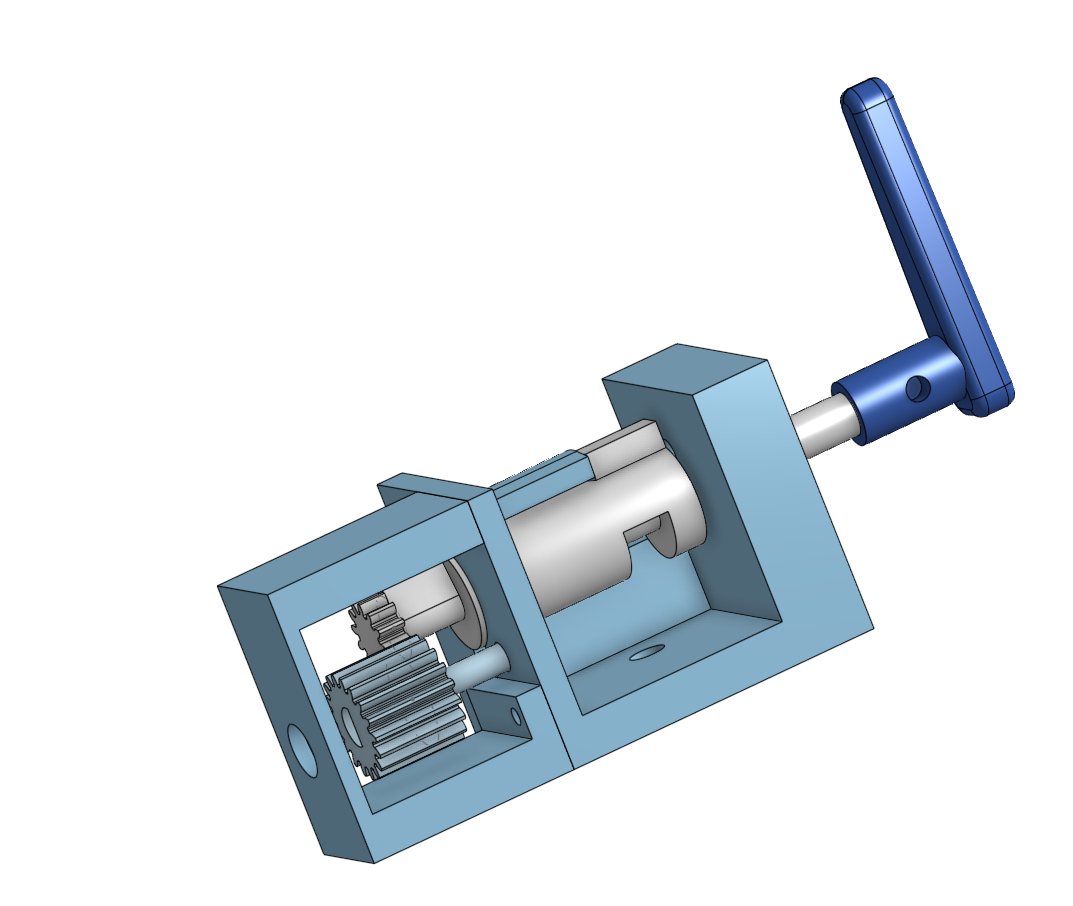
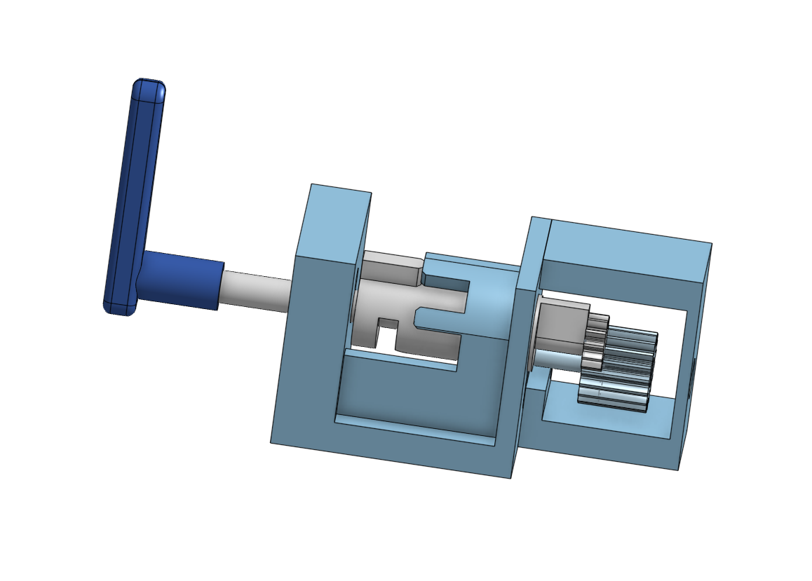
A micro switch mounts where the blue part is. I wired the normally open and closed both as two separate inputs for the Leo Bodnar controller to get the correct functionality You can see the micro switch sticking out These are the microswitches I used: https://www.amazon.com/gp/product/B07BL33XXT/ref=ppx_yo_dt_b_search_asin_title?ie=UTF8&psc=1
-
.2mm and 100m/s speed, most everything has very little detail in the z axis so smaller layer height doesn't really give you any better quality, just slows everything down
-
This is a long mission - 1hr of flying to get to the target area... I drop bombs and hit target successfully egress on the heading given in voice cues and the mission crashes out to the end screen 3-4 minutes later. I hit end mission and get the failure result. Some of the Voice Cues step on each other as well? Any ideas??? I've flown it 3 times now and I just feel like I'm wasting my time. One more mission to finish the campaign and I'm stuck.....
-
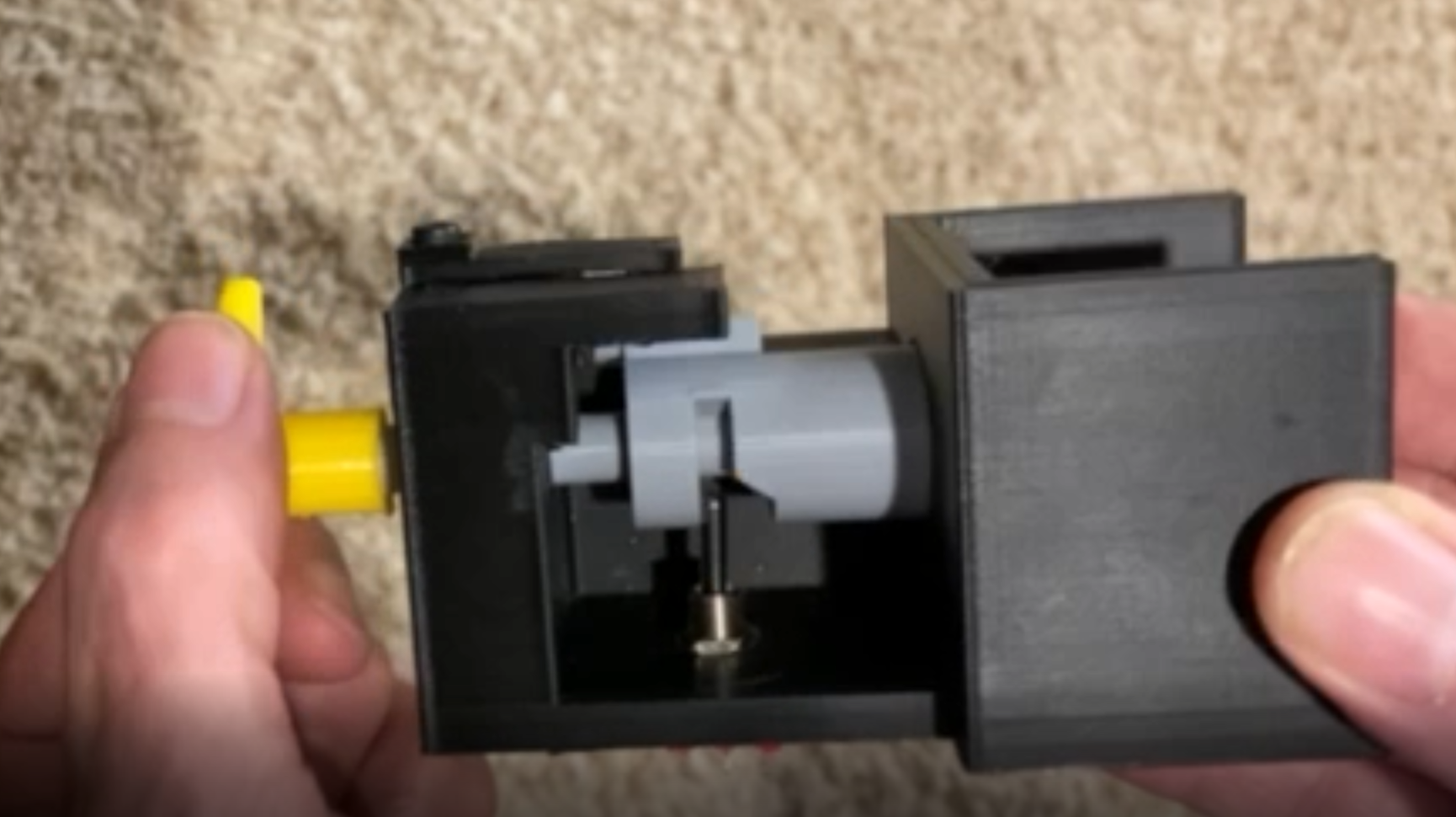
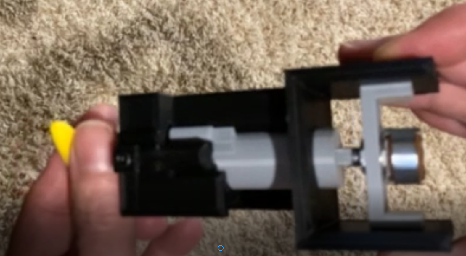
it took a good month of printing to do the side consoles. I did lose some days due to running out of filament and needing to replace my hot end. As far as cutting the panels out of flat stock. Completely agree but I just don't have access to the proper tools to be able to do it. Looks were secondary to function for me. I 'm not super happy with the way the wing fold came out. I tried to gear it to get the correct amount of rotation. 3D Printing isn't the best solution for gears. It has quite a bit of slop in it but it works for the most part. If you notice in the video I have to "straighten" it after rotating it back to the fold position. Toggle switch mounts in the bottom there for the push pull and a 3 position rotary on the back for the rotation All the 3D files are in OnShape. If you have an account, PM me and I'll share them with you
-
I didn't do a very good job of taking pics along the way of the internals so I'm not going to post a bunch of details. If you have any questions I'd be happy to answer them
-
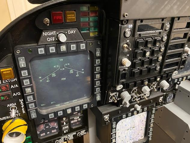
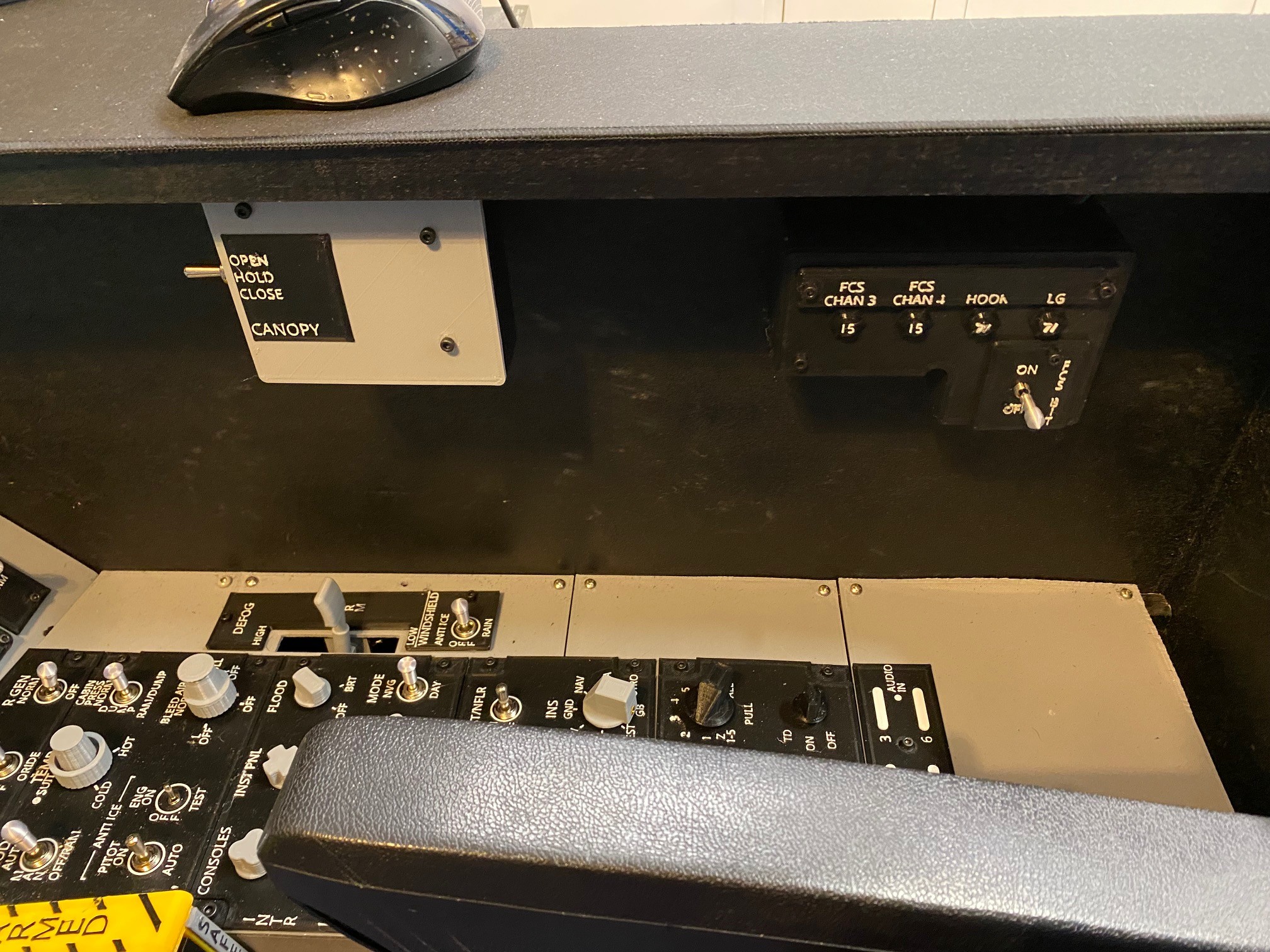
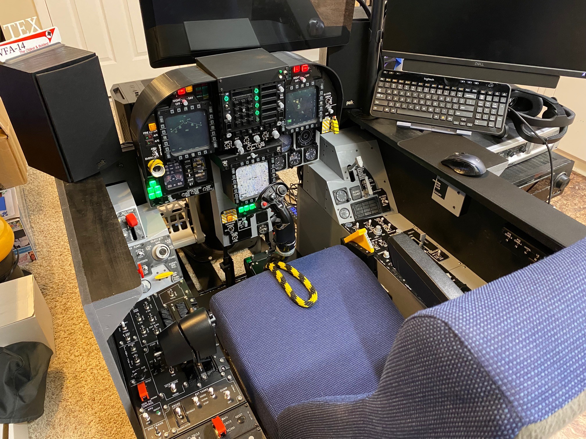
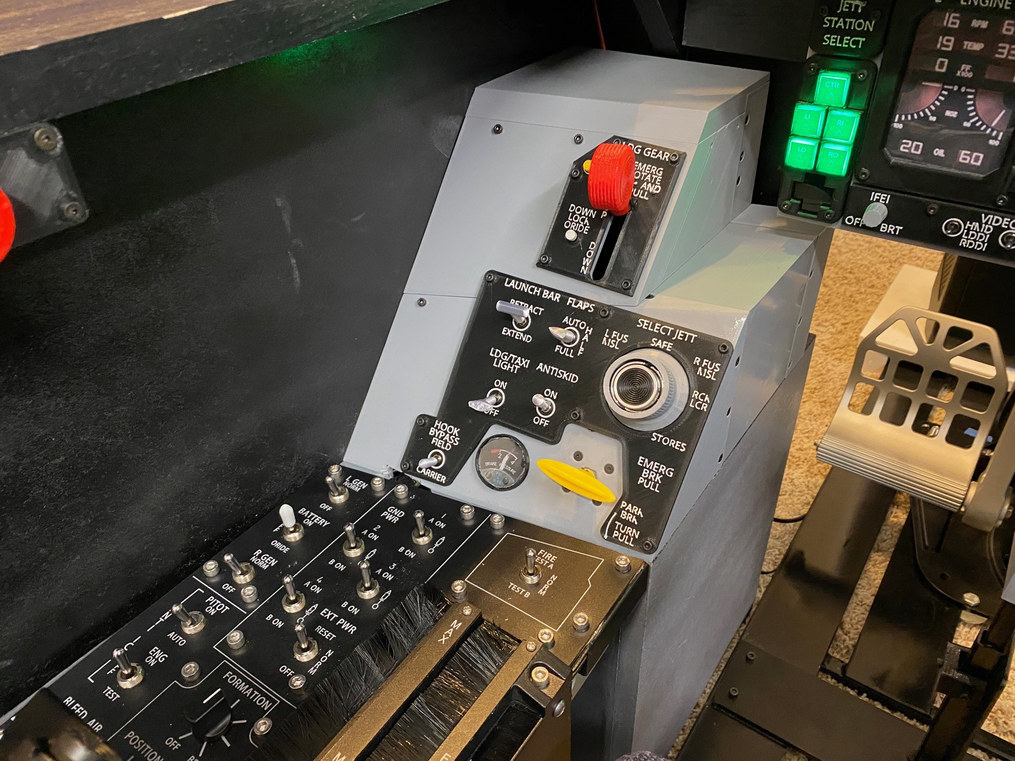
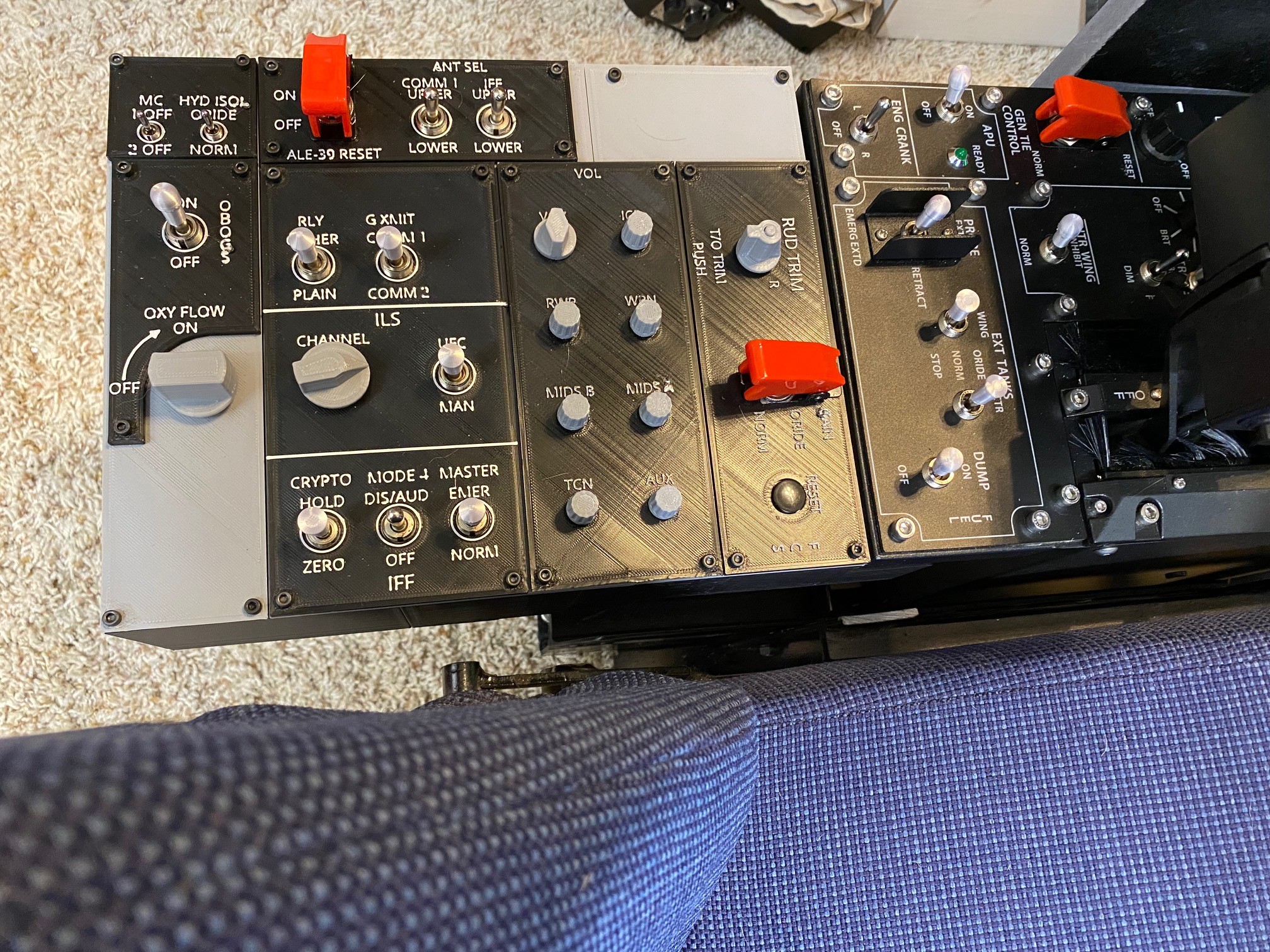
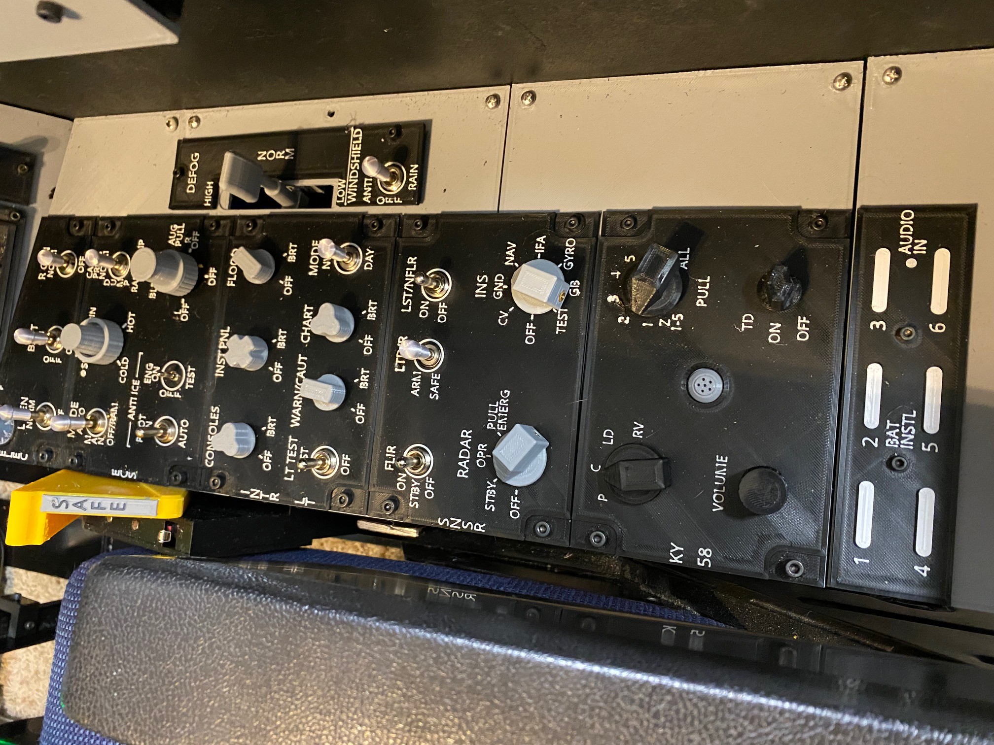
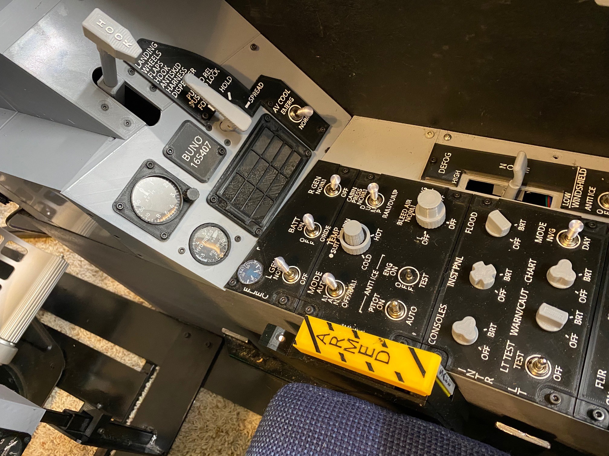
I wanted to start new thread for the update of my sim pit. I designed and built the front panel a little over a year ago and finally got around to doing the side consoles and vertical panels. The original thread on the front panel is here - https://forums.eagle.ru/topic/236378-3d-printed-hornet-front-panel-vr/#comments This was a much different kind of project as trying to get some of the controls to act remotely close to the way they are in the jet was a challenge. Here are some pics of the completed project. I'll work on adding some details YouTube Video: https://youtu.be/7_goqBNcTrE
-
You tube video of my current setup with the new side consoles https://youtu.be/7_goqBNcTrE
-
very nice.. its awesome to see someone else making my design. I just finished the side consoles. I'll post a video link soon
-
Can't figure out how to bind it either. found this.... in LSO_clickable_data.lua but I'm not smart enough to figure out how to get it to bind lements = {} elements["Button_Connector_027R"] = BUTTON(("Cut Lights") ,--[[COMMAND INDEX--]] 2, 27 ) elements["Button_Connector_028R"] = BUTTON(("WaveOff Lights"),--[[COMMAND INDEX--]] 3, 28 ) elements["Button_Connector_034R"] = BUTTON(("Deck On") ,--[[COMMAND INDEX--]] 4, 34 )
-
Anyone know how I can make the super carrier go into a CASE II recovery? I really need the clouds to stay the same for other aspects of the mission (density 9, 5000ft celling / rain) I can tweak the fog and it will go form Case I to CASE III but no matter what I do I can't get the AI to call out CASE II recovery.