JCook
-
Posts
461 -
Joined
-
Last visited
Content Type
Profiles
Forums
Events
Everything posted by JCook
-
Yup, looks like 2016 could be interesting.
-
I think this is a great idea. I don't see anything wrong with charging for your creative services. For people who don't have the time or talent to make their own skins this would be helpful.
-
Thanks for creating these panels.
-
roc Try the Otto controls catalog: http://edition.pagesuite-professional.co.uk//launch.aspx?pbid=94475dbe-02be-4af8-ad43-70219d564ad9 Look in the Trim Controls section - page 172
-
Questions about the DCS Autum Flash Sale
JCook replied to JCook's topic in DCS World 1.x (read only)
Great answers. Thanks! -
A few questions about the DCS Autum Flash Sale DCS: Flaming Cliffs 3 vs F-15C for DCS World - The F-15C is the aircraft I am most interested in during this sale. Am I getting the same F-15C is these two products? Flaming Cliffs has additional aircraft of course but is there an advantage for getting the F-15C for DCS World by itself? Are the aircraft in both of the above titles playable alongside the A10C within DCSWorld? For example can multiplayer missions be undertaken with the A10C, F-15C, Su-27m etc. all flying together? Do I need to purchase the titles on the same PC system that I would install the titles on? Can I buy online from one machine but install on my dedicated DCS sim system? Thanks
-
Lars - Have you released your panels in CAD .dxf format yet?
-
I was looking around for a engine gauge cluster solution and a way to interface those 12 gauges. Would something like this work for the Arduino? https://www.adafruit.com/product/1438 its a motor/stepper/servo shield. Several of these can be stacked together. So I'm thinking a few of these running the engine gauge cluster. What do you think?
-
Very nice work
-
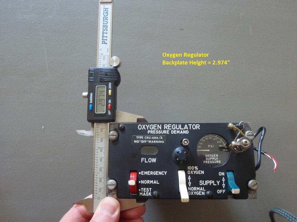
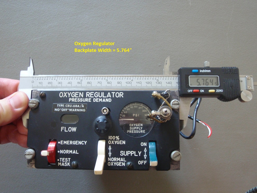
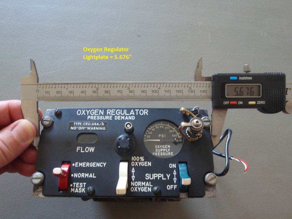
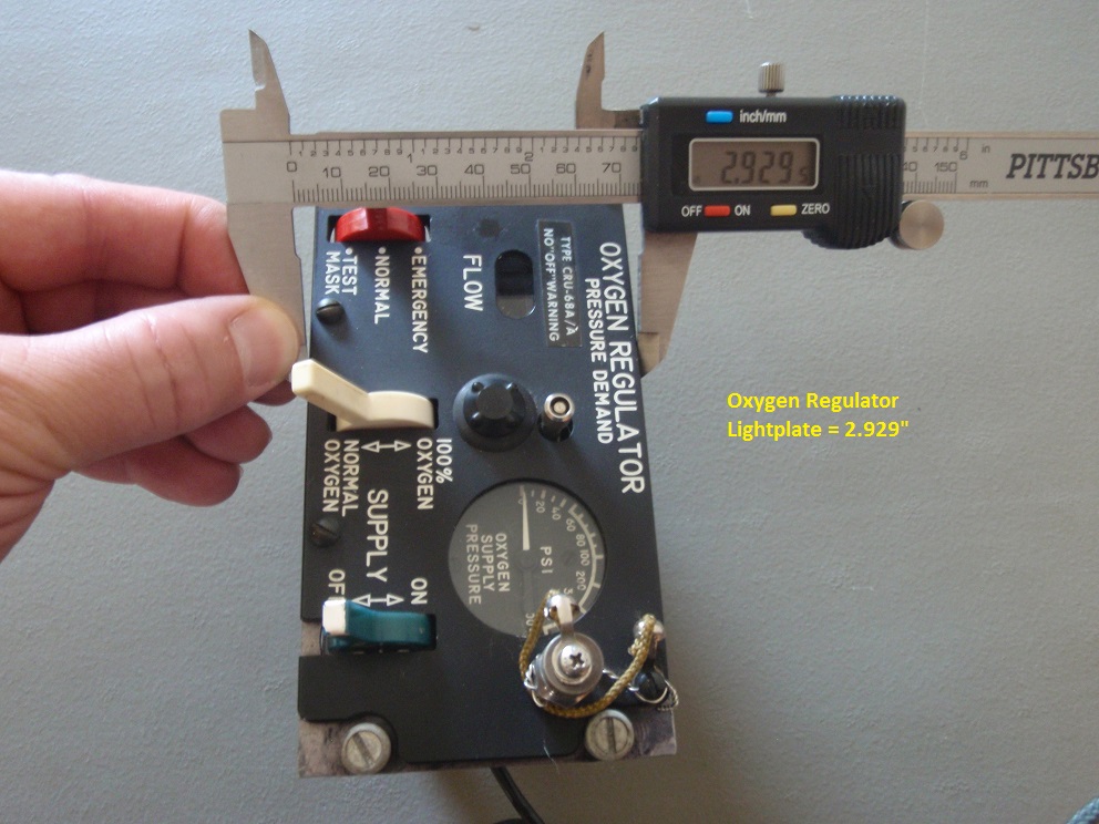
Lars As you know the standard width is 5.75". The pictures are probably more useful for the height dimension. From the height dimension perhaps you can get a better idea of the other panels. In any case these numbers (146.4056mm and 146.05mm) are close, though it would be helpful for your dxf files to be in inches instead of millimeters. John
-
Oxy Panel measurements getting this thread back on track... Lars - here are some measurements of the Oxygen Regulator panel you may find helpful. Measurements are in inches for the backplate (bottom) and the lightplate (top). John

-
Huh? vicx I agree with Deadman - you should start a new thread if you want to pursue your topic. But I have to say that what you are trying to do, as I understand it, makes no sense to me. Why have a physical pit with a virtual helmet? You're going to use a Virtual Reality headset to look around the A10's 3D cockpit and then blindly grope around for the actual physical switches, knobs and levers? :huh: Makes no sense. The whole point of building a simpit is to be able to interact with the simulation as if you were in the real cockpit. Ideally, the only video display you should see is view outside the canopy. If you're intent on a VR headset solution then maybe you should look into some VR gloves that could act as a mouse pointer in the VR cockpit display...
-
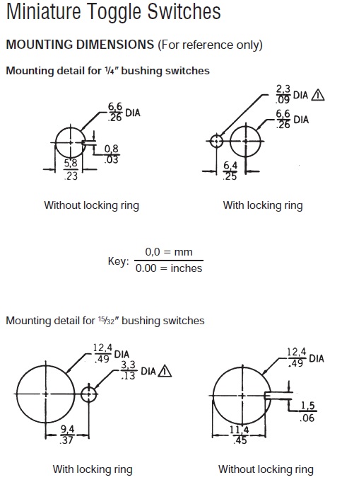
locking ring holes for the back plates Lars Locking ring holes should be added so the switches are locking in place. The ring fits into the keyway (notch) of the switch and hole in the back plate. The attached diagram shows the placement for the holes. I believe most of the switches I have been using are of the 15/32" bushing variety. I recommend placing two locking ring holes around the toggle switch hole. Place them 180 degrees apart (top-bottom or left-right) and this will allow builders more options with their switches. For example a switch may be hard to find, but a switch with the same function but different keyway orientation might be available. By having an additional ring hole on the opposite side that switch can be used and locked in place. John
-
Awesome. Thanks.
-
Good idea - white on black with green lens cover. It looks like the referenced 2x20 LCD is 116mm long. The reference I have for the EW window is more like 85mm - so that would be a tough fit. Although my reference number for the window is probably off.
-
Lars Are you also planning the Main Instrument Panel components - AHCP, Fuel, Landing Gear, Circuit Breakers, etc?
-
Very nice work. Which display board did you use for the CMSP - where can they be purchased?
-
Thanks Lars for your work and special thanks to Deadman for providing the needed info for accuracy. Much appreciation to you both.
-
Hi Lars. Great work you are doing. Thank you. The dxf format would be my request. I don't have a 3D modeling package yet - just regular CAD. Any chance you can save these in a zip format? Thanks John
-
Thanks Mike That will help a lot of the builders using real instruments.
-
weeb Which dimension are you trying to determine - the width of the EW panel or the height? The standard width of a Dzus back plate is 5.75" wide. I believe the acrylic "text" plate that sits on top of it is slightly smaller 1/32" on all sides. If you have accurate console dimensions for the Dzus rail and accurate panel dimensions things should align properly. If one or both of the console / panel dimensions are not accurate you'll have a alignment problem which is what you've experienced. Hope this helps.
-
weeb I think you meant 145mm for that width dimension in your drawing, not 1450mm. Big difference.
-
COM questions Thanks guys for your input. I've been doing some experimenting and I did my preliminary testing with an Arduino Duo which was recognized on COM4. I bought an Arduino Mega2560 to use for the UFC and it was recognized by Windows on COM6. Then I needed to change the type of Arduino and the port in the Arduino IDE. When things didn't work I realized I also needed to change the COM port in the connect-serial-port.cmd file as well. Now the Arduino Mega works. Now the question is when I start building my panels and am connecting multiple Arduinos how does the connect-serial-port.com read all the different COM ports from the boards? Do I run multiple versions of the program or do I change the settings in the program? Also, I will be building a DCS World PC and will be attaching all of these Arduinos to the new PC - So they will potentially have different COM ports assigned on the new machine as opposed to my testing PC. Correct?
-
rocketeer The indicator above the PRI button corresponds to that button's function being active. Presumably the UNK button / indicator works similar, even though it appears UNK is not modeled in the sim. Reference Page 409 in the manual: PRI (Priority) Button. The Azimuth Indicator can display up to 16 symbols simultaneously; however, this can lead to a rather crowded display. By pressing the PRI button on the CMSC, you can toggle between OPEN mode that can display the 16 highest priority threats or PRI mode which will only show the five highest threats. When PRI is active, the green light above the button will be lit. SEP (Separate) Button. To expand groupings of symbols on the RWR display such that they can be more easily read, you may press the SEP button on the CMSC. Upon doing so, the symbols will be separated radially outwards from each other. UNK (Unknown) Button. No function.
-
Sahaj - are your stick extensions still available? I sent you an eMail from your website a while ago...