Lino_Germany
-
Posts
1943 -
Joined
-
Last visited
-
Days Won
7
Content Type
Profiles
Forums
Events
Everything posted by Lino_Germany
-

The Huey, the UHF ARC-51 and the Nevada Map
Lino_Germany replied to Lino_Germany's topic in DCS: UH-1H
The stated ATC frequencies have nothing to do with the real ones. They are defined by the developers. Nellis AFB, Sim: 125.00 254.00 39.20 Nellis AFB, Real: ATIS: 270.1 NELLIS GROUND: 121.8 / 275.8 NELLIS TOWER: 132.55 / 327.0 NELLIS APPROACH: 118.125 / 291.725 NELLIS DEPARTURE: 135.1 / 385.4 So my question is, why can´t they use ATC frequencies at the NTTR map from the default settings that happen to tie into the Black Sea map? -
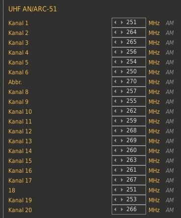
We have the opportunity to communicate with ATC at the Nevada map via preset channels at the AN/ARC-51 UHF radio. So why are these preset channels fitted with frequencies for Creech AFB (channel 1 AND channel 17) but no channel for the ATC at Groom Lake AFB???? Certainly there is a preset channel for McCarran (channel 19) and Nellis (channel 5). So again: Why two times 251 MHz, but no 252 MHz for Groom Lake?

-
Where can one find a good (official) airport diagram from Creech AFB (Indian Springs) and Groom Lake?
-
Hi Blech, thanks for your reply. Until release version 1.0 everything is heavily work in progress, all data has to be verified and at the moment all seen data is something like a placeholder. Nonetheless your contribution will flow into the beacon map.
-
Not at all. Vacation and 3 days without my children...:music_whistling:
-
Hi guys, version 0.1 of the "Nevada Beacon Map" is ready and you can download it here: http://www.digitalcombatsimulator.com/en/files/1587399/ Please keep in mind that this is a very early release and everything is much work in progress. Of course I am open for any comment regarding improvements and possible bugs.
-
Hi guys. Thanks for your kind words. I've a lot to do at the moment (with focus on translation of flight manuals into german language). The Beacon Map (Nevada Edition) will come next year.
-
Thanks for reporting.
-
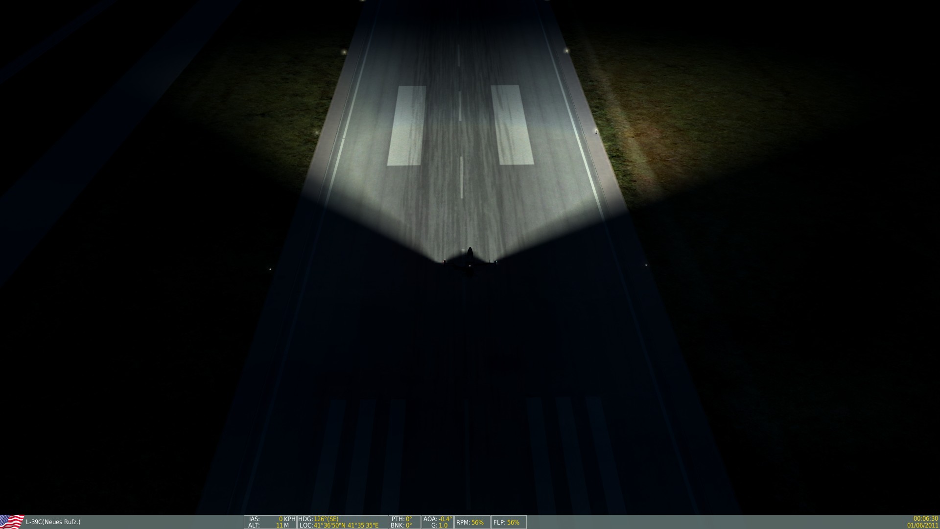
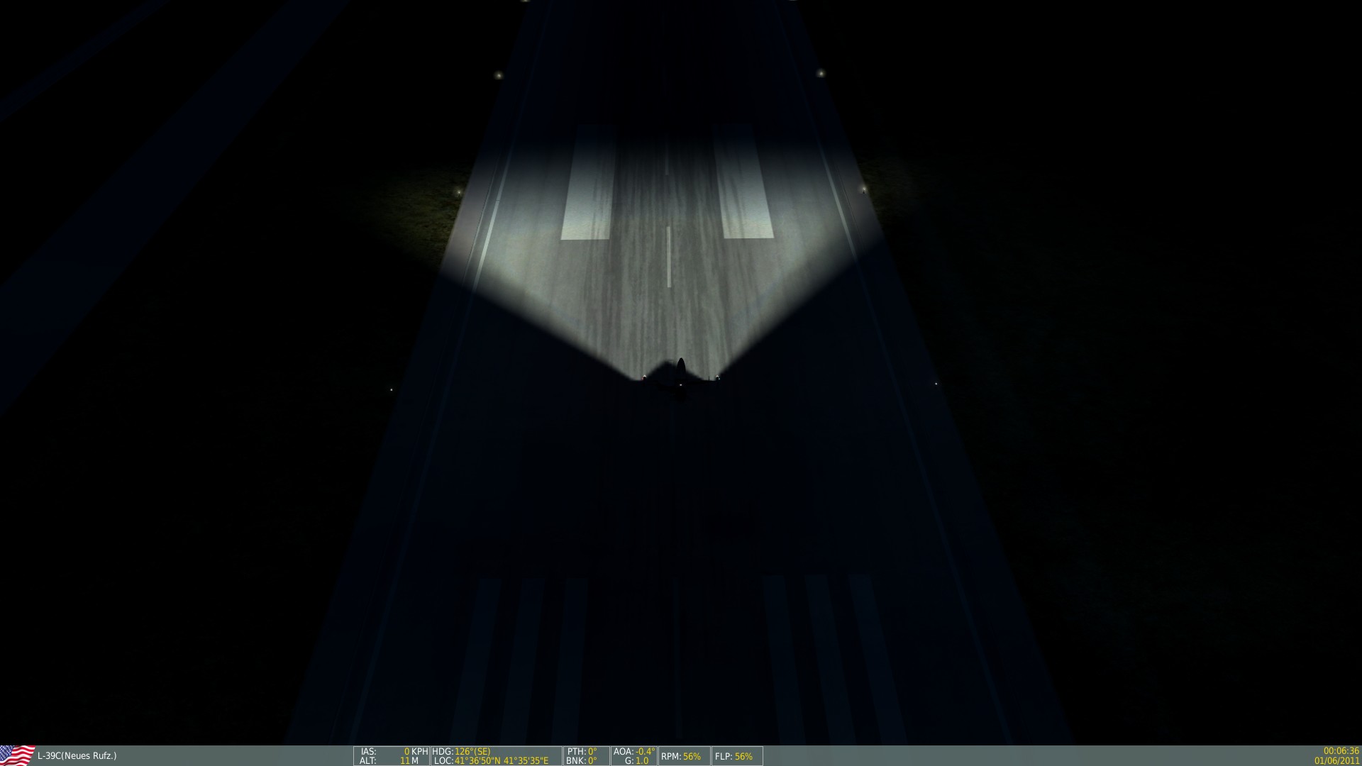
You are absolutely right, Dr_Arrow. After testing I also come to the conclusion that there is no benefit in using the landing lights. @derelor: If there are no plans by ED to fix this, all your explanations in the flight manual refer to the real L-39C and not the simulated one. Until now the "larger all-round pattern" rests with the taxi light.
-
Keep in mind that the aircraft stands on ground. The light beam of the landing light points more in direction of the aircrafts longitudinal axis.
-
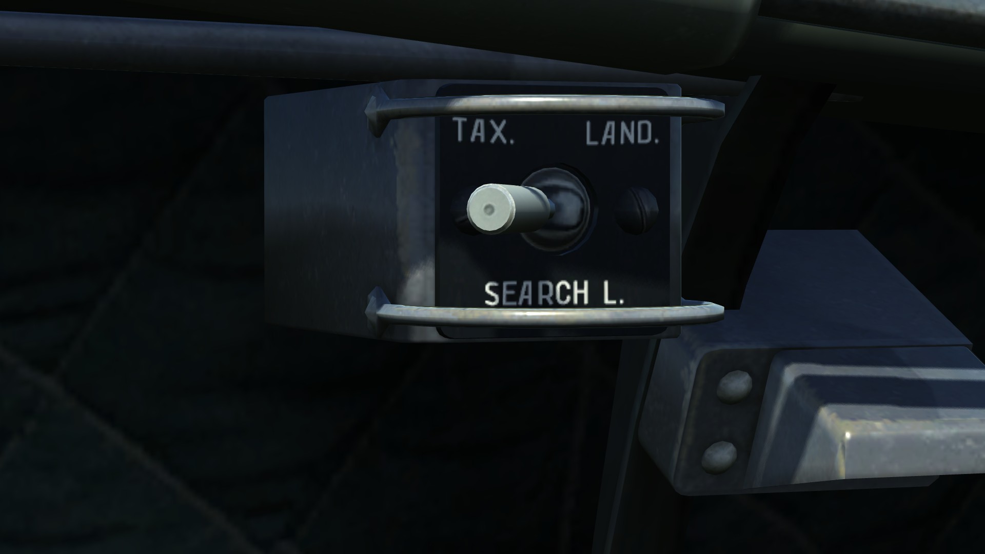
LIGHTING SYSTEM The aircraft lighting equipment is basically divided into three essential subsystems: exterior and interior lighting subsystems and warning, caution and advisory indicator subsystem. EXTERIOR LIGHTING The aircraft exterior lighting equipment consists of the following lights: - two landing/taxi lights - one left-hand red position light - one right-hand green position light - one tail, white position light - three white landing gear down lights, one on each landing gear POSITION LIGHTS (NAV LIGHTS) The NAV lights are controlled by two three-position switches, located on the right console auxiliary switch panel in the forward cockpit (position lights control panel "NAVIG. LIGHTS"): - Mode control - can be selected to flash position "FLICKER", middle OFF or steady "FIXED" position. - Intensity control "BRIGHTNESS" - can be selected to DIM (30%), BRT (60%) or MAX (100%). This switch functions only if the mode control switch is out of OFF position. The NAV lights are powered by 28 V DC and protected by the "NAV. LIGHTS/HAND LAMP" CB on the Aft CB/ Swich Panel in the forward cockpit. LANDING GEAR DOWN LIGHTS A white "landing gear down" light is mounted on each landing gear strut. The lights are automatically switched on, by a terminal switch, when the landing gear is extended, provided that the navigation light switch is not in OFF position. The circuit is protected by "NAV. LIGHTS/HAND LAMP" CB on the Aft CB/Switch Panel. http://forums.eagle.ru/showpost.php?p=2535283&postcount=1
-
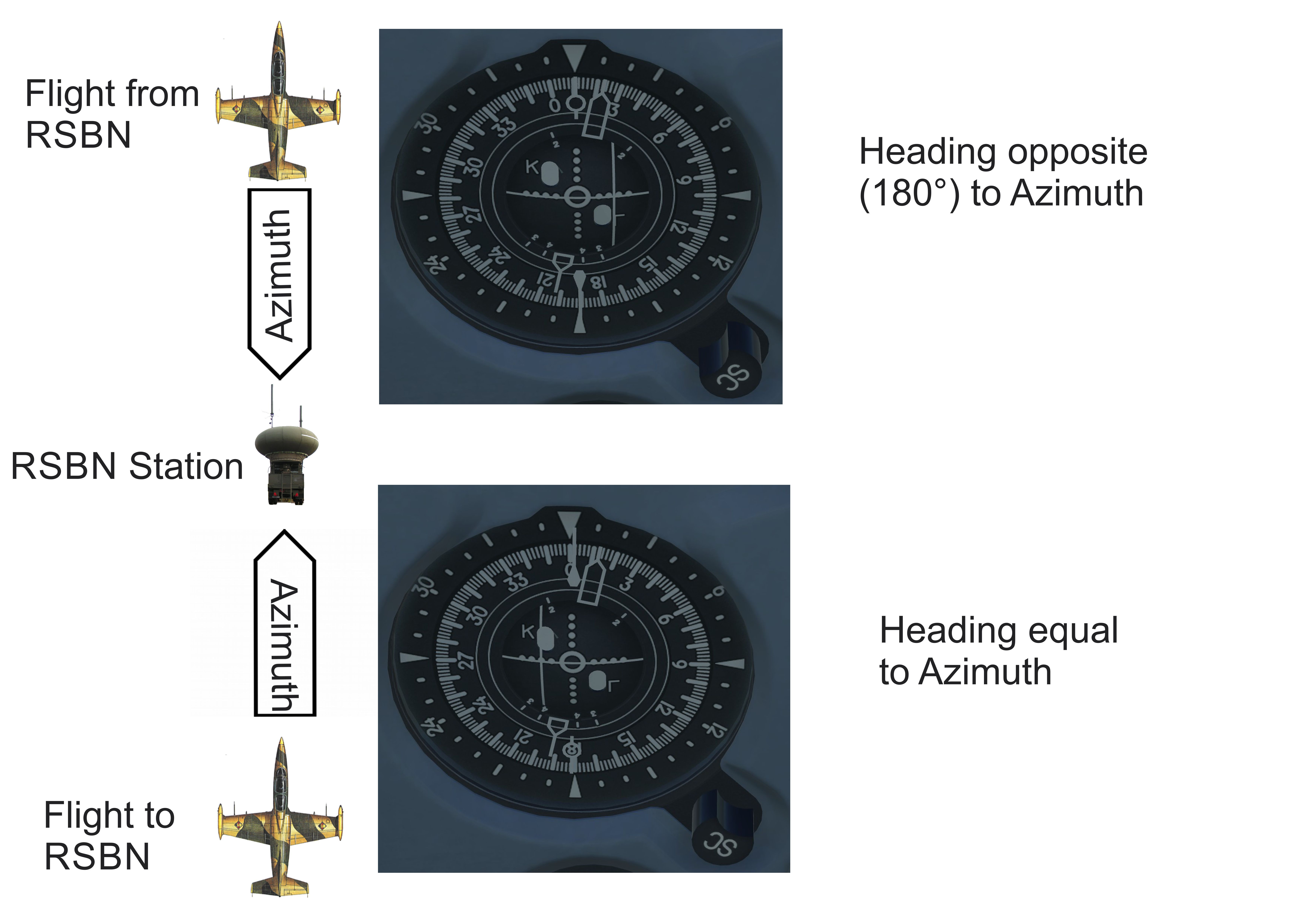
The 16 channel numbers in yellow hexagons are valid for the MiG-21bis by Letherneck only. It is an early form of implementing RSBN and PRMG into DCS World. The more realistic approach for RSBN and PRMG is now implemented with the release of DCS World 1.5 Beta and the L-39C module (with just four supported airfields). These channels are also shown in the beacon map.
-
If we work on the premise that the original Aero L-39 manual is error-free, the problem is the definition of "larger all-round pattern". 1. Landing light filament Aero manual: Simulation: 2. Taxi light filament Aero manual: Simulation: All in all I think your elaboration is perfectly okay, because it gives an idea of what "larger all-round pattern" could mean. It is a pleasure to see that someone equalizes the partly bulky sections of the manual. The community will be grateful, me too.
-
ED manual, page 180 "gears" has to be changed to "flaps".
-
ED manual, page 178 The "window direction" should be read "wind direction".
-
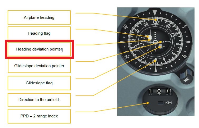
ED manual page 177, 179 We have two different terms (heading deviation pointer / course deviation pointer) for the same component of the RMI. Which one is correct?
-
Thank you, Zhivuchiy, for your clarification. Maybe this fact needs to be better developed and explained in the manual.
-
As I understand it...
-
ED manual, page 177 In my opinion the green and blue marked sentences have to be swapped out.
-
ED manual, page 177 Neue Bitmap.bmp Heading of the airplane is always read at the uppermost position, under the upside-down white triangle, at the inner scale of the RMI. The pointer with the circle is fully independent from the aircraft heading and its sharp end shows the BEARING to the by channel selected RSBN-station.
-
ED manual, page 167 "retract" has to be changed to "extend".
-
ED manual, page 166 The last sentence should read: at altitude of 50—70 m retract flaps first at 25°, then completely, perform another landing approach.
-
The correct emergency procedure to extend the flaps is to move the emergency flap extension valve lever all the way back. I think there is nothing wrong and the text statement is clear. Why should all the other emergency levers pulled back in a case that only affects the flaps? In this case the text transition is very rough and should be reworked. In particular, there is a lack of context to the previous writing. I think the whole section "EMERGENCY HYDRAULIC SYSTEM" is not dealt with in sufficient detail in this manual.
-
http://forums.eagle.ru/showthread.php?t=151343
-
Version 1.44 ready for download. New in version 1.44: - ARC station 3-1 4 implemented - RSBN and PRMG (new DCS 1.5 standard) implemented Download link: http://www.digitalcombatsimulator.com/en/files/588673/